Loading ...
Loading ...
Loading ...
INST
ALLATION OVERVIEW
C1. Attach Mounting Plate to W
all
C2. Prepare Top Cabinet
C4.
C5.
Mount the Microwave Oven
IMPORTANT NOTES:
•
Make sure the screws for the blower motor and blower
plate are securely tightened when they are reinstalled.
This will help to prevent excessive vibration.
• Make sure the motor wiring has been properly routed
and secured, and that the wires are not pinched.
Installation Instructions
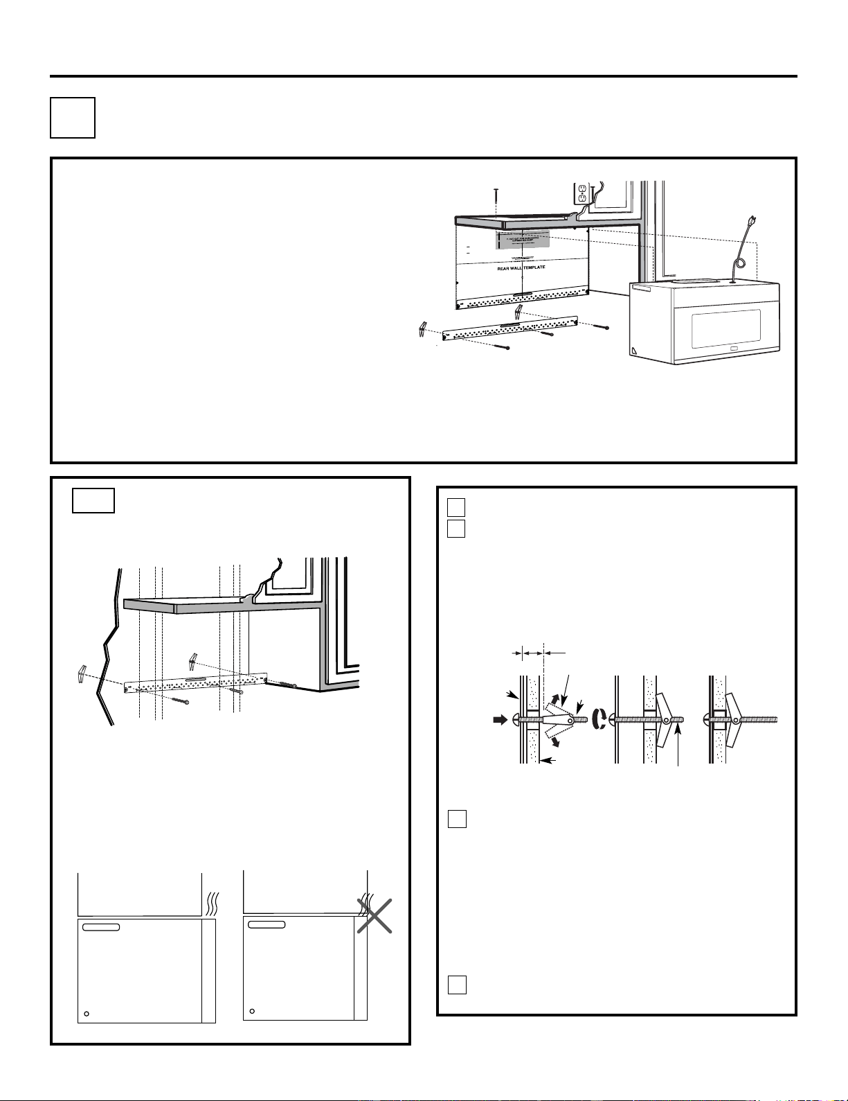
Place the mounting plate against the wall and
insert the toggle wings into the holes in the wall
to mount the plate.
NOTE: Before tightening toggle bolts and wood
screw, make sure the bott m of the mounting plate
touch the bottom of the cabinet when pushed flush
against the wall and that the plate is properly
centered under the cabinet.
CAUTION: Be careful to avoid pinching fingers
between the back of the mounting plate and the wall.
Tighten all bolts. Pull the plate away from the wall
to help tighten the bolts.
4
3
A
TTACH THE MOUNTING
PLATE TO THE WALL
C1.
Attach the plate to the wall using toggle bolts.
At least one wood screw must be used to attach
the plate to a wall stud.
Remove the toggle wings from the bolts.
Insert the bolts into the mounting plate through
the holes designated to go into dr
ywall and
reattach the toggle wings to
3
⁄
4
″ (19 mm) onto
each bolt.
1
Wa
ll
Mounting
Plate
Spacing for Toggles
More Than Wall
Thickness
Bolt End
Toggle
Bolt
Toggle Wings
T
o use toggle bolts:
2
RECIRCULA
TING
(Non-V
ented Ductless)
C
Install or change Charcoal Filter
C3. Check Blower Plate
NOTE:
Cabinet
Cabinet
If the cabinet depth including the cabinet doors
is more than 13""'' then the unit must be spaced
out from wall using adequate materials supporting
150 Ibs to allow proper top vent air exhaust/intake.
o
EN-20
3
/8"TO EDG
E
NOTE:
IT IS VERY IMPORTANT TO
READ AND FOLLOWTHE DIRECTIO
N
S
IN THE INSTALLAT
ION INSTRU
CTIO
N
S
BE
FO
RE PR
OCEEDING
WITH T
HIS
REAR W
ALL TEM
PLATE.
T
his RearWall Template serves to position th
e bottom
mou
nting pl
a
teand to loc
ate the hori
z
onta
l e
x
haust
ou
tlet.
1. Use a level
to
check
that the te
m
plate
i
s po
s
itioned
a
ccu
rately.
2. Locate
and
mark at least ones
tu
d on the
le
ft or
r
ight
s
id
e
of th
e centerl
ine
.
I
t
is impo
rtan
t to u
se at leas
t one
wood
screw
mo
unted
fir
mly
i
n
a
s
tud
to support the weight
of
the mi
cr
owa
ve.
Mar
k
t
w
o ad
di
tion
al, ev
e
nly
spa
ced
locations
f
or the
s
uppl
ied to
g
gle bol
t
s.
3. Dr
ill
h
ol
es in
the m
ar
ked loc
ations
.
Where th
er
e is
a stud, dr
il
l a 3/16" hole for wood screw
s
. For h
o
les
that
do
n
ot line upwith a
s
tud, d
rill 5/8"
holes for
togg
l
e bolts
.
DO
NOT INSTALL
THE
MO
U
NTI
NG PLATE
AT
THISTIME.
4. Re
mov
e th
e templa
te fro
m
the rea
r
wall.
5.Review the Installation Instruction book for your
insta
l
l
atio
n si
tuat
i
on
.
L
ocate and mark holes to align with holes in the
mountingplate.
IMPORTANT:
LOCATE
AT LEA
ST
O
N
E
STUD
ON EI
T
HER
SID
E O
F
THE CENTERLINE.
MARKTHE LOCATION FOR 2 ADDITIONAL, EVENLY
SPACE
D TO
GGLE
BO
LTS IN THE MOUN
TING
PLATE
AREA
.
Locate and mar
k
holes to align with holes
in t
he
mountingplate.
IMP
ORTANT
:
LOCATE AT LEAST O
NE
STUD
O
N EITHER SID
E OF
TH
E
CENT
E
R
LI
N
E
.
MARK
THE LOCATIO
N
FOR 2 ADDITIONAL, EVENLY
SP
ACED
TOGGLE BOLTS IN
THE MO
UNTING PLATE
AREA
.
Trim the rear wall template alongthe do
tted line.
Trim the rear wall template alongthe dotted line.
12"
4"
Darl
evue
lt
aa l
aho
j
a
pa
rac
ons
u
lt
ar
la
versión
enE
spa
ño
l.
Loading ...
Loading ...
Loading ...