
Loading ...
Loading ...
Loading ...
INSTALLATION OVERVIEW
B1. Prepare Rear W
all
B3. Attach Mounting Plate to Wall
B4. Prepare Top Cabinet
B5. Adjust Blower
B6. Mount the Microwave Oven
IMPORTANT NOTES:
•
Make sure the screws for the
blower motor and blower plate
are securely tightened when
they are reinstalled. This will
help to prevent excessive
vibration.
•
been properly routed and secured,
and that the wires are not pinched.
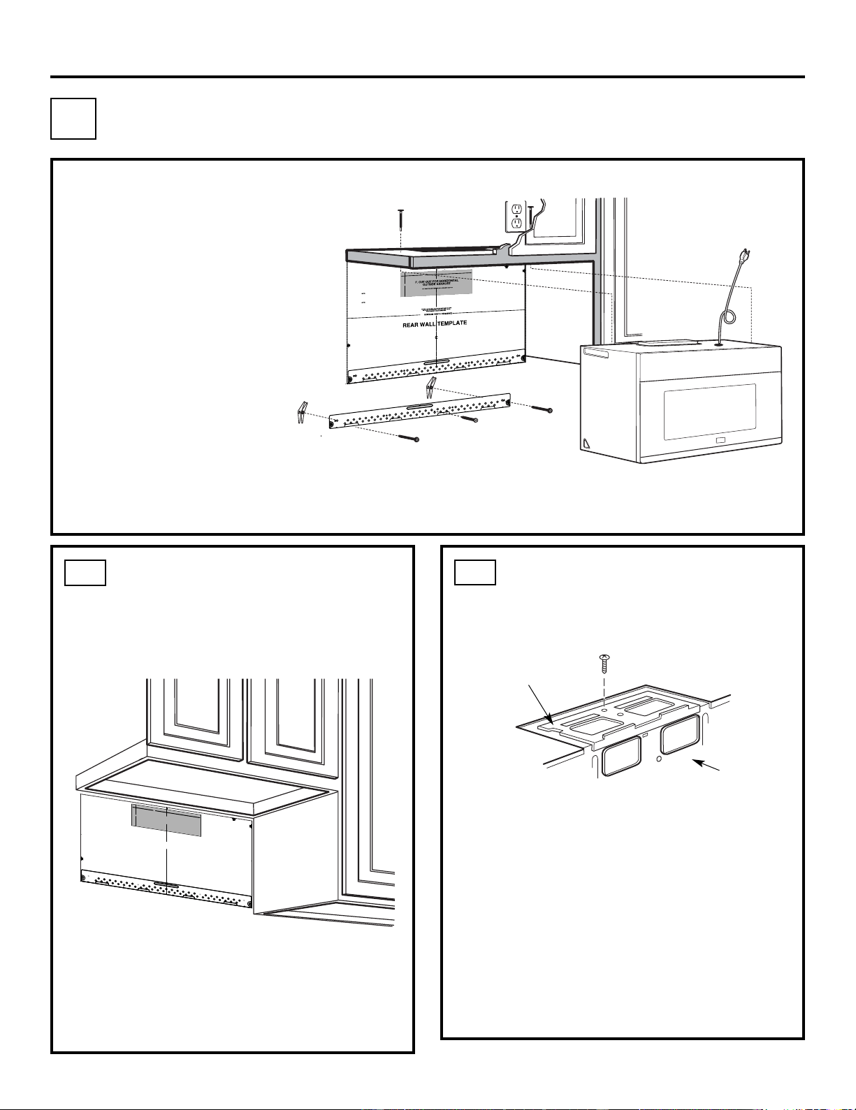
Remove and save the screw that holds the blower
plate to the microwave. Lift off the blower plate.
Back of
Microwave
Installation Instructions
PREP
ARING THE REAR WALL
FOR OUTSIDE BACK EXHAUST
B1.
Y
ou need to cut an opening in the rear wall for
outside exhaust.
•
Read the instructions on the REAR
W
ALL TEMPLATE.
•
T
ape it to the rear wall.
• Cut the opening, following the instructions of the
REAR W
ALL TEMPLATE.
B2.
OUTSIDE BACK EXHAUST
(Horizontal Duct)
B
Blower Plate
REMOVE BLOWER PLATE
B2. Remove Blower Plate
3/8" TO EDGE
NOTE: IT IS VE
RY IMPORTANT TO
READ AND FOLLOW THE DIRECTIONS
IN THE INSTALLATION INSTRUCTIONS
BEFORE PROCEEDING WITH THIS
REAR WALL TEMPLATE.
This Rear Wall Template serves to position the bottom
mounting plate and to locate the horizontal exhaust
outlet.
1. Use a level to check that the template is positioned
accurately.
2. Locate and mark at least one stud on the left or
right side of the centerline.
It is important to use at least one wood
screw mounted firmly in a stud to support the weight
of the microwave. Mark two additional, evenly spaced
locations for the supplied toggle bolts.
3. Drill holes in the marked locations. Where there is
a stud, drill a 3/16" hole for wood screws. For holes
that do not line up with a stud, drill 5/8" holes for
toggle bolts.
DO NOT INSTALL THE MOUNTING PLATE
AT THIS TIME.
4. Remove the template from the rear wall.
5. Review the Installation Instruction book for your
installation situation.
Locate and mark holes to align with holes in the
mounting plate.
IMPORTANT:
LOCATE
AT LEAST ONE STUD ON EITHER SIDE OF
THE CENTERLINE.
MARK THE LOCATION FOR
2 ADDITIONAL, EVENLY
SPACED TOGGLE BOLTS IN THE MOUNTING PLATE
AREA.
Locate and mark holes to align with holes in the
mounting plate.
IMPORTA
NT:
LOCATE AT LEAST ONE STUD ON EITHER SIDE OF
THE CENTERLINE.
MARK THE LOCATION FOR 2 ADDITIONAL, EVENLY
SPACED TOGGLE BOLTS IN THE MOUNTING PLATE
AREA.
Trim the rear wall template along the dotted line.
Trim the rear wall template along the dotted line.
12"
4"
Darle vuelta a la hoja para consultar la
versión en Español.
Make sure the motor wiring has
EN-16
3/8
"TO
EDG
E
NOTE: IT IS VERY
I
M
POR
TANT TO
READ AND FOLLOW
THE
D
IRECTIONS
IN THE INSTALLAT
ION INSTRU
CTI
O
N
S
BE
FO
RE PR
O
CEEDING
WITH T
H
IS
REAR W
ALL TEM
PLATE
.
Th
i
s
R
ea
rW
a
ll Template ser
v
e
s to positio
n th
e
botto
m
mounting platea
nd
to loc
ate th
e hor
i
z
on
tal exhau
st
ou
t
let.
1. Us
e a l
evelto
ch
ec
k
th
at the
tem
pla
te is po
s
itioned
a
ccu
r
ately
.
2. L
oc
ate
andmar
k at lea
st o
nes
tu
d on th
e
le
ft or
r
ight side of the cen
te
rli
ne
.
It is impor
ta
n
t to u
se at leas
t
one wood
scre
w
mounted firmly
i
n a s
tud
to supp
ort the weight
ofthe mic
r
ow
a
ve. Mark t
w
o
a
dditi
on
a
l, ev
en
ly
spa
c
ed
lo
c
atio
ns
fo
r the
s
uppl
ied to
g
gle bol
t
s.
3. Dri
ll
h
ol
es in
the mar
k
ed locatio
ns
.Wher
e t
h
er
e is
a s
tud, dr
il
l
a 3/1
6"
h
ol
e fo
r wood scr
ews. F
or
holes
that
do
n
o
t line upw
ith
a
s
tud, dr
il
l 5/8" h
oles
fo
r
toggl
e bolts
.
DO NOT
IN
S
T
AL
L
T
H
E MO
U
NTIN
G P
L
ATE
AT
T
HIS
T
IME.
4. Re
move
th
e template fr
o
m
the rea
r
wal
l.
5.Review
the In
s
tall
a
tionInst
ructio
n bo
ok for
y
our
insta
l
l
ation si
tua
t
i
on
.
Locate an
d mar
k holes
to align with holes
in t
he
mountingp
late.
IMPO
RTANT
:
LOCATE
AT LEA
ST
O
N
E
STUD
O
N EI
THER
SI
D
E O
F
THE
CENTE
R
LI
N
E.
MARK
T
HE LOCATIO
NF
O
R 2 ADDITIONAL, EV
ENL
Y
SP
ACED TOGGLE BO
LTS IN THE MOUN
TING
PLATE
AREA
.
Locate and mar
k holes to ali
gn with holes
in t
he
mountingplate.
IMP
ORTANT
:
LOC
A
TE AT LEAST O
NE
STUD
O
N EI
THER SI
D
E O
F
TH
E
CENT
ERLI
N
E
.
MARK
THE LOCATIO
N
FOR 2 ADDITION
A
L, EVENLY
SPACEDTOGGLE BOLTS IN THE MO
UNTING PLATE
AREA.
Trim the r
e
ar wall tem
plat
e alongthe do
tt
ed line.
Trim the rear
wall tem
pla
t
e alongthe dotted lin
e.
12"
4"
Da
r
l
evue
lt
a
a
la
h
o
j
a
pa
ra
consu
l
t
ar
la
ver
sión
en
Espa
ñol.
24"
24"
Loading ...
Loading ...
Loading ...