Loading ...
Loading ...
Loading ...
OPERATION
DEPTH OF CUT ADJUSTMENTS
We recommend that cuts be made at a depth not ex..
¢eedlng 1/8" and that several passes be made to
teach depths of cut greater than 1/8"
loUNPLUG YOUR ROUTER°
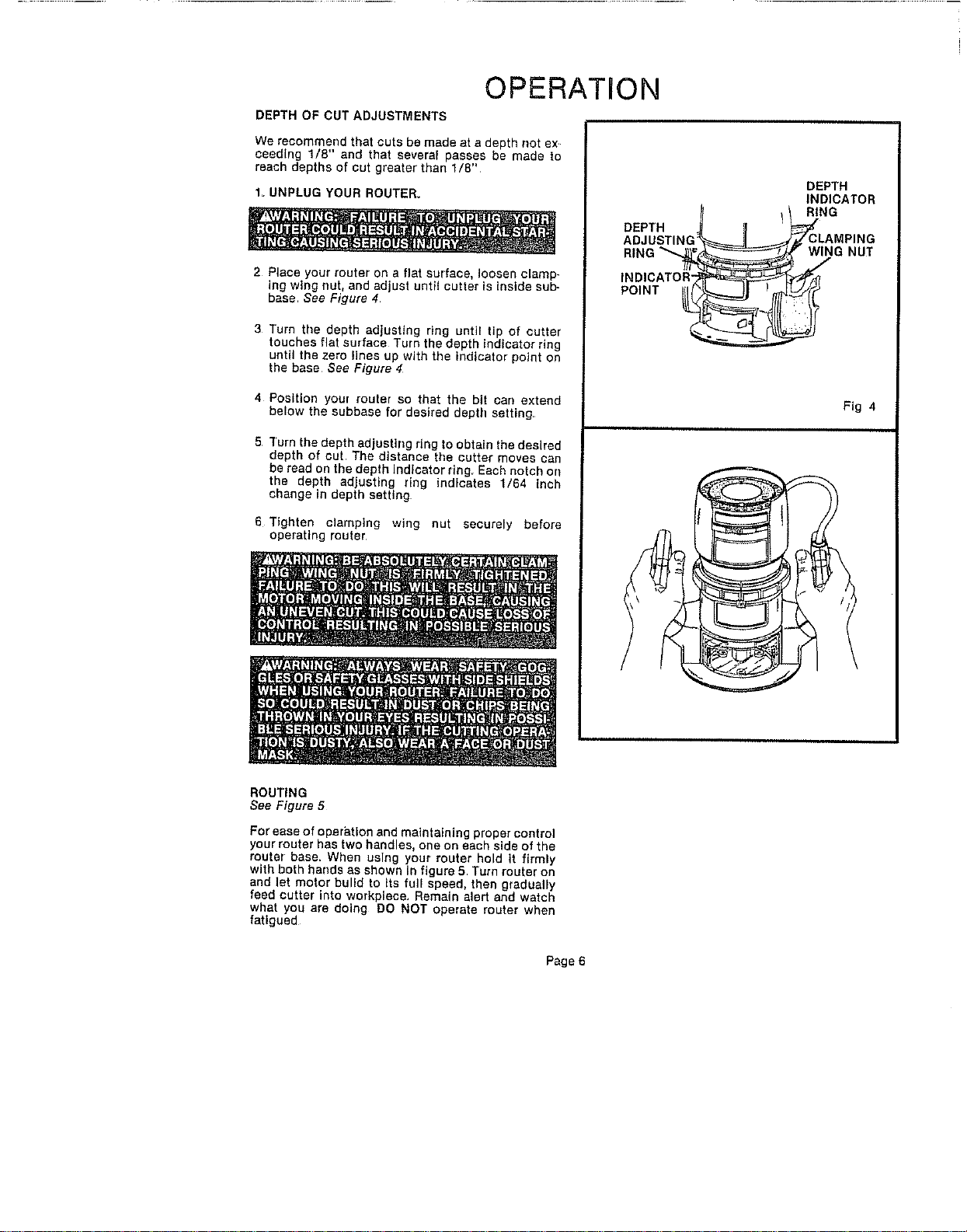
2 Place your router on a flat surface, loosen clamp-
ing wing nut, and adjust until cutter ts Inside sub-
base See Figure 4.
3 Turn the depth adjusting rtng until tip of cutter
touches flat surface Turn the depth indicator ring
until the zero lines up with the Indicator point on
the base See Figure 4
4 Position your router so that the bit san extend
below the subbase for desired depth setting
5 ]'urn the depth adjusting ring to obtain the desired
depth of cut. The distance the cutter moves can
be read on the depth indicator ring. Eash notch on
the depth adjusting ring indicates 1/64 inch
change in depth setting
6 Tighten clamping wing nut securely before
operating router
DEPTH
ADJUSTING:
RING
INDICATOR":
POINT ___
J
DEPTH
INDICATOR
RIND
_CwLAMPING
tNG NUT
Ftg 4
ROUTING
See Figure 5
For ease of operation and maintaining proper control
your router has two handles, one on each side of the
router base. When uelng your router ho_d tt firmly
with both hands as shown In figure 5 Turn router on
and let motor build to Its full speed, then gradually
feed cutter into workpieca. Rama(n alert and watch
what you are doing DO NOT operate router when
fatigued
Page 6
Loading ...
Loading ...
Loading ...