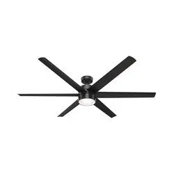
Installation Manual for Hunter 59628


Installing the Ceiling Bracket
You have two options for installation. Pick which one works best for your location. Remove any existing bracket prior to installation. Only use the provided Hunter ceiling bracket that came in your fan’s box
WARNING To avoid possible electrical shock, before installing your fan, disconnect the power by turning off the circuit breakers to the outlet box associated with the wall switch location.
Option 1: Machine Screws
Use machine screws (provided with outlet box) and washers when securing to existing ceiling fan-rated outlet box. Make sure it is securely installed and is acceptable for fan support of 31.8 kg (70 lbs) or less.
Option 2: Wood Screws
Use wood screws and washers (included) when securing to support structure with approved electrical outlet box. Drill 9/64” pilot holes in support structure to aid in securing ceiling bracket with hardware found in the hardware bag.
Hunter Pro Tip: The machine screws are the ones that came with your outlet box.
Installing the Downrod
Follow below if you are using the downrod that came pre-assembled in your box. Need to install a longer or shorter downrod? Check out the guide at the end of this manual.
- Remove the pre-installed setscrew so that the downrod can be inserted.
- Pass all wires to one side of horizontal bar in downrod assembly. Hand tighten the downrod (at least 4–5 full turns) until it stops. Trim the wires coming from the fan so that 8-inches remain coming from the top of the downrod.
- Tighten the setscrew with pliers. DO NOT HAND TIGHTEN.
WARNING FAN FALL HAZARD
To prevent SERIOUS INJURY or DEATH:
• ALWAYS tighten setscrew with pliers.
• DO NOT hand tighten setscrew.
• CHECK the setscrew is tight using pliers each time you change fan direction.
Hanging the Fan
NOTICE To prevent damage to fan, ALWAYS lift holding either the fan housing or the downrod.
Place the downrod ball into the slot in the ceiling bracket.
Progress Check: Your fan should look like this
Wiring the Fan
Have a single switch? Follow these steps:
- Connect the white (grounded) wire from the ceiling to the white wire from the fan
- Connect the black (ungrounded) wire from the ceiling to the black wire from the fan.
- Cap the blue wire from the fan. You will not need it for single switch wiring.
- Connect the three grounding wires (green, green/yellow stripe, or bare copper) coming from the ceiling, downrod, and hanging bracket.
WARNING All wiring must be in accordance with national and local electrical codes ANSI/NFPA 70. If you are unfamiliar with wiring or in doubt, consult a qualified electrician.
WARNING The ceiling fan must be grounded. If the ground wire for the installation site is not present, immediately STOP installation and consult a qualified electrician.
Have dual switches? Follow these steps:
- Connect the white (grounded) wire from the ceiling to the white wire from the fan.
- Connect the black (ungrounded) wire from the ceiling to the black wire from the fan.
- Connect the second ungrounded (light) wire from the ceiling to the blue wire from the fan.
- Connect the three grounding wires (green, green/yellow stripe, or bare copper) coming from the ceiling, downrod, and hanging bracket
Installing the Canopy
- Lift the canopy into place so that the screw holes are aligned.
- Insert the two canopy screws found in the hardware bag.
Installing the Blades:
Insert the blade into the blade slot around the center screw. Put the blade washers found in the hardware bag onto the blade screws found in the hardware bag. Then install the blade screws to secure each blade to the fan.
Repeat x6
Assembling the LIght Kit
- Partially install two light kit screws, found in the hardware bag, halfway into the motor housing as shown. It does not matter which two screw holes you choose.
- Align the keyhole slots in the top of the light kit assembly with the partially installed assembly screws. Wrap the keyhole slots around the screws and twist counterclockwise. Install the third light kit screw. Tighten all screws securely.
- Partially install two of the light kit screws found in the bag. It does not matter which two screw holes you choose. Connect the single-pin connectors from the LED assembly to the connectors from the fan. Connect the white wires together. Connect the blue and black wires together.
- Align the keyhole slots in the light kit housing with the two screws. Make sure all the wires from the fan and the light kit are snug inside the center of the light kit, not pinched in between the upper switch housing and the light kit or hanging out of the sides.
- Turn the light kit counterclockwise until the light kit screws are firmly situated in the narrow end of the keyhole slots. Install the third screw and tighten all three screws securely.
WARNING FAN FALL HAZARD Make sure all screws are tight to secure the light fixture.
Installing the Bulbs and Glass
Lift the globe and align the notches in the globe with the tabs in the light kit.
Note: Fan style may vary
Attach the globe by lifting and turning clockwise one third of a full turn of the glass until it stops.
NOTE: Check to ensure proper engagement.
WARNING GLASS FALL HAZARD To prevent SERIOUS INJURY or DEATH, make sure that glass is properly secured.
Preparing the Wall Control
- Turning off the power Ensure the power is OFF at the outlet box and wall switch location before proceeding with installation.
- Installing the battery To access the battery compartment, slide the battery door up. Replace the used battery with two AAA batteries when needed.
- Wiring the Wall Control Connect the grounding wire from the wall control to the ground control from the switch box using the provided wire nuts. Connect the “LIVE IN” from the switch box to the “~VAC” from the wall control using the provided wire nuts. Connect the “LIVE OUT” from the switch box to the “FAN” out from the wall control using the provided wire nuts. Push all wires into the switch box.
- Installing the Wall Control Install the longer screws through the slots in the wall control into the switch box screw holes.
- Installing the Wall Plate Install the shorter screws through the wall control plate and into the screw holes in the wall control.
- Turning on the power
- The remote transmitter is already paired to the receiver and ready to use. If you need to pair your remote, cycle power to the fan by turning power off and back on at the wall switch (or circuit breaker if necessary). Within three minutes, do the following
- Reference the included remote function card for information on how to use your wall control!