Loading ...
Loading ...
Loading ...
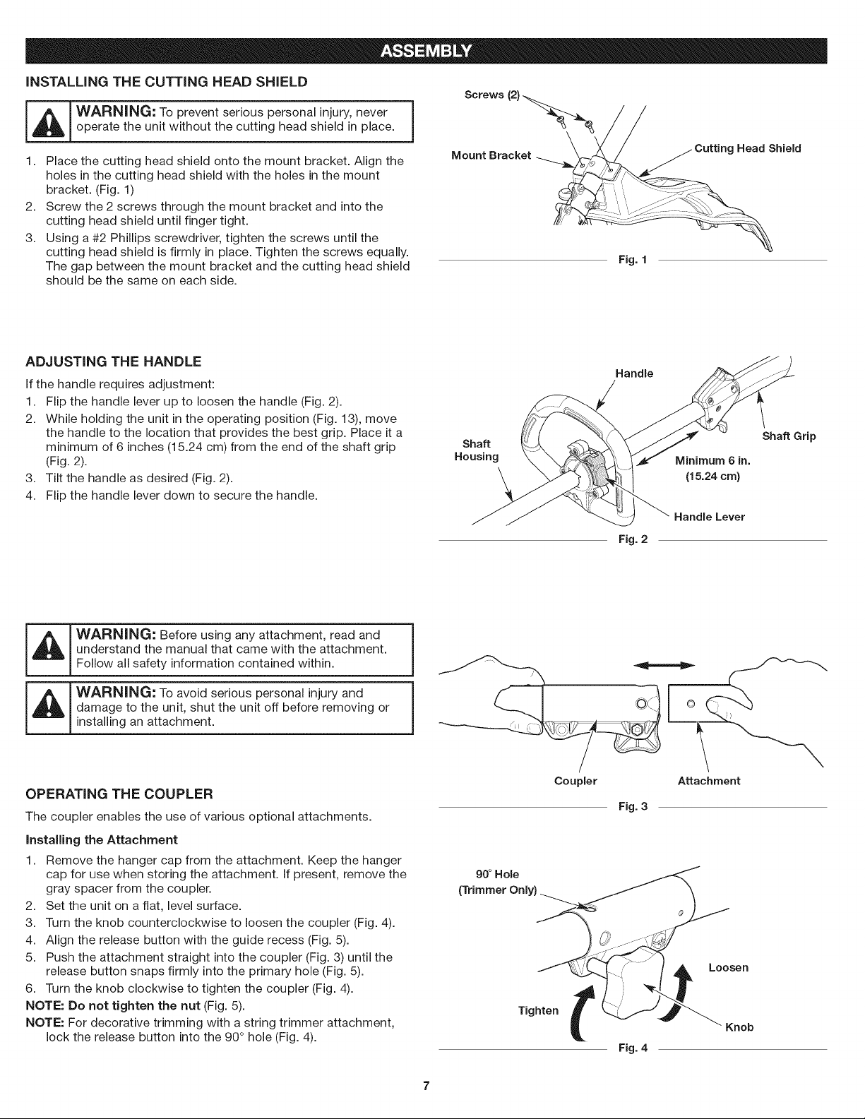
iNSTALLiNG THE CUTTING HEAD SHIELD
_ WARNING; To prevent serious personal injury, never j
operate the unit without the cutting head shield in place.
1. Place the cutting head shield onto the mount bracket. Align the
holes in the cutting head shield with the holes in the mount
bracket. (Fig. 1)
Screw the 2 screws through the mount bracket and into the
cutting head shield until finger tight.
Using a #2 Phillips screwdriver, tighten the screws until the
cutting head shield is firmly in place. Tighten the screws equally.
The gap between the mount bracket and the cutting head shield
should be the same on each side.
2.
3.
Screws (2}
Mount Bracket " hield
Fig. 1
ADJUSTING THE HANDLE
If the handle requires adjustment:
1. Flip the handle lever up to loosen the handle (Fig. 2).
2. While holding the unit in the operating position (Fig. 13), move
the handle to the location that provides the best grip. Place it a
minimum of 6 inches (15.24 cm) from the end of the shaft grip
(Fig. 2).
3. Tilt the handle as desired (Fig. 2).
4. Flip the handle lever down to secure the handle.
Handle
Shaft Shaft Grip
Housing Minimum 6 in.
(15.24 cm)
Fig. 2
Handle Lever
understand the manual that came with the attachment.
Follow all safety information contained within.
WARN,NG: Toavoidseriouspersona,injuryand j
damage to the unit, shut the unit off before removing or
installing an attachment.
OPERATING THE COUPLER
The coupler enables the use of various optional attachments.
installing the Attachment
1. Remove the hanger cap from the attachment. Keep the hanger
cap for use when storing the attachment. If present, remove the
gray spacer from the coupler.
2. Set the unit on a flat, level surface.
3. Turn the knob counterclockwise to loosen the coupler (Fig. 4).
4. Align the release button with the guide recess (Fig. 5).
5. Push the attachment straight into the coupler (Fig. 3) until the
release button snaps firmly into the primary hole (Fig. 5).
6. Turn the knob clockwise to tighten the coupler (Fig. 4).
NOTE: Do not tighten the nut (Fig. 5).
NOTE: For decorative trimming with a string trimmer attachment,
lock the release button into the 90 ° hole (Fig. 4).
Coupler Attachment
Fig. 3
90 ° Hole
(Trimmer Only)
Tighten t
Fig. 4
Loosen
Knob
Loading ...
Loading ...
Loading ...