Loading ...
Loading ...
Loading ...
13
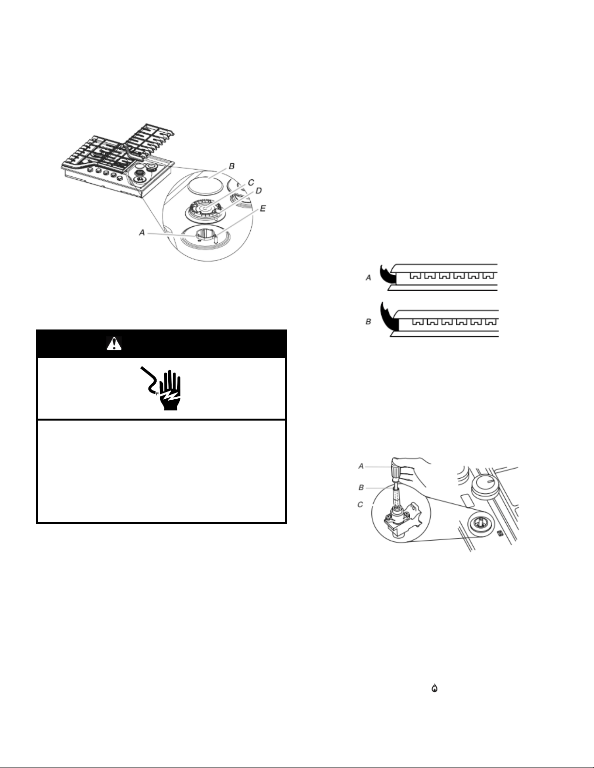
3. Remove surface burner caps, burner base and grates from
parts package. Align notches in burner caps with pins in
burner base.
Align orifice holder in burner base with igniter electrode.
Burner caps should be level when properly positioned. If
burner caps are not properly positioned, surface burners will
not light. Place burner grates over burners and caps.
A. Orifice holder
B. Burner cap
C. Gas tube opening
D. Burner base
E. Igniter electrode
WARNING
Electrical Shock Hazard
Plug into a grounded 3 or 4 prong outlet.
Do not remove ground prong.
Do not use an adapter.
Do not use an extension cord.
Failure to follow these instructions can result in death,
fire, or electrical shock.
4. Plug into a grounded 3 prong outlet.
Complete Installation
Electronic Ignition System
Initial lighting and gas flame adjustments
Surface burners use electronic igniters in place of standing pilots.
When the cooktop control knob is turned to the “IGNITE” position,
the system creates a spark to light the burner. This sparking
continues, as long as the control knob is turned to “IGNITE”.
Check Operation of Surface Burners
Push in and turn the surface burners control knobs to light.
The surface burner flame should light within 4 seconds. The first
time a surface burner is lit, it may take longer that 4 seconds to
light because of air in the gas line.
Check the flame on “HIGH” for a blue color. It should be clean and
soft in character. No yellow tip, blowing or lifting of flame should
occur. Occasional orange flashes are normal and reflect different
elements in the air or gas.
After verifying the proper burner operation, turn the control knobs
to “OFF.”
If burners do not light properly:
� Turn surface burner control knob to the “OFF” position.
� Check that the power supply cord is plugged in and the circuit
breaker has not tripped or the fuse blown.
� Check that the gas shutoff valve is set to the “open” position.
� Check that burner caps are properly positioned on burner
bases.
Recheck operation of surface burners. If a burner does not light at
this point, contact your dealer or authorized service company for
assistance.
Check Flame Height
Adjust the height of surface burner flames.
The surface burner low flame should be a steady blue flame
approximately 1/4" (6.4 mm) high.
A. Low flame
B. High flame
Adjustment for Single Valve:
1. Set the burner flame to LO.
2. Remove the control knob.
3. Hold knob stem with a pair of pliers. Use a 3/32" (#0 [2 mm])
flat-blade screwdriver to turn the screw located within the shaft
of the control knob stem until the flame is the proper size.
Turn adjustment screw “C” to the right to reduce flame height,
turn adjustment screw to the left to increase flame height.
A. 3/32" (#0 [2.0 mm]) flat-blade screwdriver (screwdriver
shaft must be a minimum of 2" [5.1 cm] long)
B. Control knob stem opening
C. Adjustment screw location
4. Replace the control knob.
5. Test the flame by turning the control from LO to HI, checking
the flame at each setting.
IMPORTANT: Dual valve adjustments must be performed by a
qualified installer or service agency.
Power failure
In case of prolonged power failure, the surface burners can be lit
manually. Hold a lit match near a burner and turn knob
counterclockwise to IGNITE/Lite/
. After burner lights, turn knob
to setting. Do not use a grill or griddle accessory during a power
failure as the vent fan will not operate.
Loading ...
Loading ...
Loading ...