Loading ...
Loading ...
Loading ...
12
3. Use a 15/16" (2.4 cm) combination wrench and channel lock
pliers to attach the flexible connector to the adapters. Check
that connector is not kinked.
IMPORTANT: All connections must be wrench-tightened. Do
not make connections to the gas regulator too tight. Making
the connections too tight may crack the regulator and cause a
gas leak. Do not allow the regulator to turn when tightening
fittings.
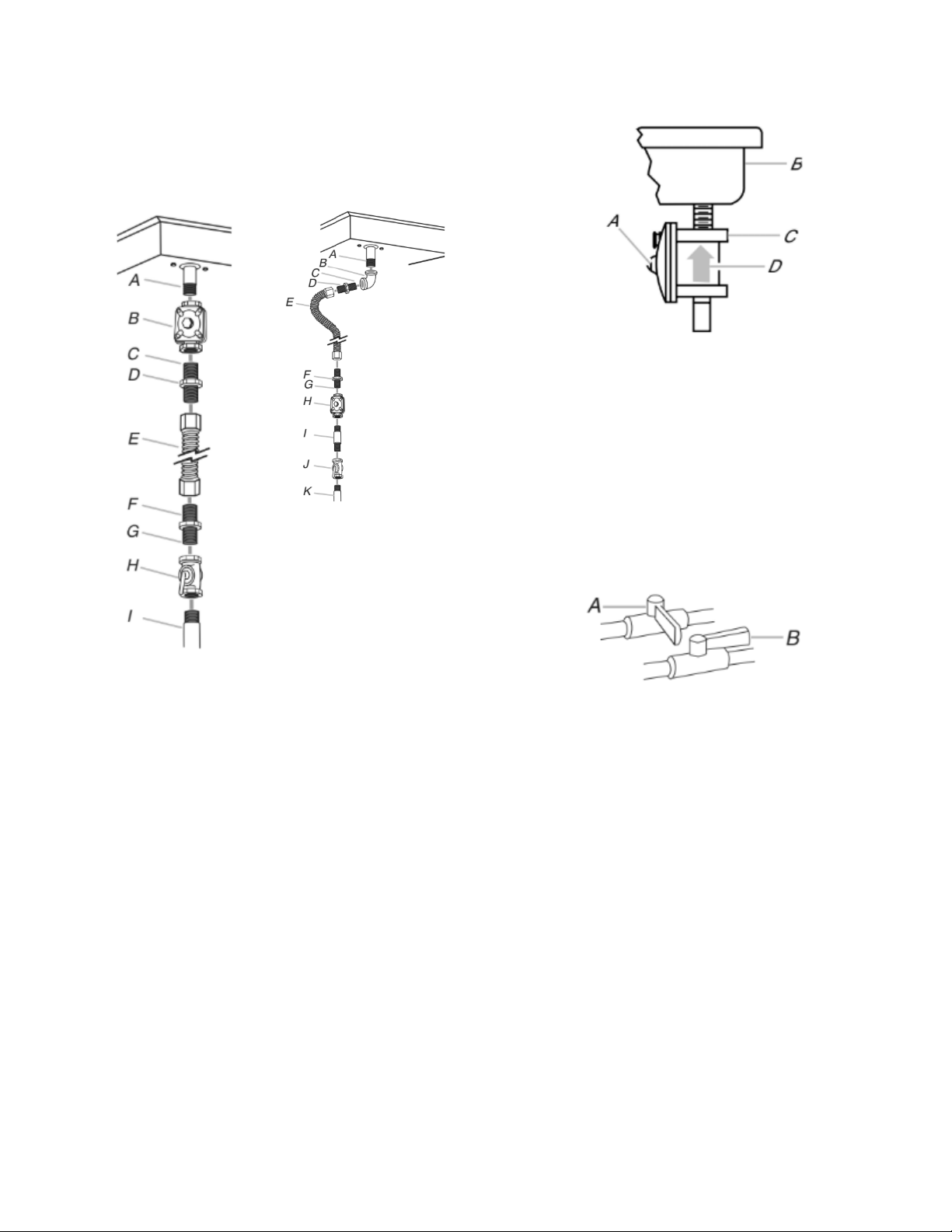
A. Manifold entrance
B. Gas pressure regulator
C. Use pipe-joint compound.
D. Adapter (must have 1/2"
(1.3 cm) male pipe thread)
E. Flexible connector
F. Adapter
G. Use pipe-joint compound.
H. Manual gas shutoff valve
I. 1/2" (1.3 cm) or 3/4"
(1.9 cm) gas pipe
A. Manifold entrance
B. 3/4" (1.9 cm) elbow
C. Use pipe-joint compound.
D. Adapter (must have 3/8"
(9.5 mm) male pipe thread)
E. Flexible connector (pass
through wall between
cabinets)
F. Adapter (must have 3/8"
(9.5 mm) male pipe thread)
G. Use pipe-joint compound.
H. Appliance pressure
regulator (supplied)
I. 1/2" (1.3 cm) or 3/4"
(1.9 cm) gas pipe
J. Manual gas shutoff valve
K. 1/2" (1.3 cm) or 3/4"
(1.9 cm) gas pipe
4. Install the pressure regulator with the arrow pointing in the
direction toward the bottom of the cooktop base and in a
position where you can reach the regulator access cap.
A. Access cap
B. Rear of cooktop
C. Gas pressure regulator
D. Up arrow. Regulator must be installed with arrow pointing up to
cooktop bottom
Use only pipe-joint compound made for use with Natural and
propane gas.
Do not use TEFLON
®
tape. You will need to determine the fittings
required depending on your installation.
Complete Connection
1. Open the manual shutoff valve in the gas supply line. The
valve is open when the handle is parallel to the gas pipe.
A. Closed valve
B. Open valve
2. Test all connections by brushing on an approved noncorrosive
leak-detection solution. Bubbles will show a leak. Correct any
leak found.
Loading ...
Loading ...
Loading ...