
Owner's Manual
II:RAFTSMnN°I
23.0 HP
ELECTRIC START
50" MOWER
6 SPEED
GARDEN TRACTOR
Model No,
917.275030
e Safety
• Assembly
s Operation
• Maintenance
• Repair Parts
This product has a low emission engine which operates
differently from previously built engines. Before you start the en-
gine, read and understand this Owner's Manual.
CAUTION:
Read and follow all Safety
Rules and Instructions before
operating this equipment,
For answers to your questions
about this product, Call:
1-800-659-5917
Sear• Craftsman Help Line
5 am - 5 pro,Mon- Sat
SEARS, ROEBUCK AND CO., HOFFMAN ESTATES, IL 60179
Visit our Craftsman website:www.sears.com/craftsman
Warranty ............................................... 2
Safety Rules ......................................... 3
Product Specifications .......................... 6
Assembly .............................................. 8
Operation ............................................ 12
Maintenance Schedule ...................... 18
Maintenance ....................................... 18
Service and Adjustments ....................22
Storage ...............................................29
Troubleshooting .................................30
Repair Parts........................................34
Parts Ordering ..................... Back Cover
LIMITED TWO YEAR WARRANTY ON CRAFTSMAN RIDING EQUIPMENT PARTS
For two (2) years from the date of purchase, if this Craftsman Riding Equipment is
maintained, lubdcated and tuned up according to the instructions in the owner's
manual, Sears will repair or replace, free of charge, any parts found to be defective in
matedal or workmanship. Warranty service is available free of charge by taking your
Craftsman riding equipment to your nearest Sears Service Center. In-home warranty
service is available but a trip charge will apply. This warranty applies only while this
product is in the United States.
This Warranty does not cover:
• Expendable items which become worn during normal use, such as blades, spark
plugs, air cleaners, belts and oil filters.
• Tire replacement or repair caused by punctures from outside objects, such as nails,
thorns, stumps, or glass.
• Repairs necessary because of operator abuse, including but not limited to, damage
caused by towing objects beyond the capability of the dding equipment, impacting
objects that bend the frame or crankshaft, or over speeding the engine,
• Repairs necessary because of operator negligence, including but not limited to,
electrical and mechanical damage caused by improper storage, failure to use the
proper grade and amount of engine oil, failure to keep the deck clear of flammable
debds, or the failure to maintain the equipment according to the instructions con-
tained in the owner's manual.
• Engine (fuel system) cleaning or repairs caused by fuel determined to be contami-
nated or oxidized (stale). In general, fuel should be used within thirty (30) days of its
purchase date.
• Riding equipment used for commercial or rental purposes.
LIMITED 90 DAY WARRANTY ON BATTERY
For ninety (90) days from date of purchase, if any battery included with this dding
equipment proves defective in material or workmanship and our testing determines the
battery will not hold a charge, Sears will replace the battery at no charge. Warranty
service is available free of charge by taking your Craftsman riding equipment to your
nearest Sears Service Center. In-home warranty service is available but a trip charge
will apply. This warranty applies only while this product is in the United States.
TO LOCATE THE NEAREST SEARS SERVICE CENTER OR TO SCHEDULE IN-HOME
WARRANTY SERVICE, SIMPLY CONTACT SEARS AT 1-800-4-MY-HOME
This Warranty gives you specific legal dghts, and you may also have other rights which
may vary from stateto state.
Seam, Roebuck and Co., D/817 WA, Hoffman Estates, IL 60179
MPORTANT This cutt ng mach ne is capable of amputating hands and feet and
throwing objects. Failure to observe the fo low ng safety instructions could result in
serious injury or death.
I. GENERAL OPERATION
• Read, understand, and follow all
instructions in the manual and on the
machine before starting.
• Only allow responsible adults, who are
familiar with the instructions, to operate
the machine.
• Clear the area of objects such as
rocks, toys, wire, etc., which could be
picked up and thrown by the blade.
• Be sure the area is clear of other
people before mowing. Stop machine
if anyone enters the area.
• Never carry passengers,
• Do not mow in reverse unless abso-
lutely necessary. Always look down
and behind before and while backing.
• Be aware of the mower discharge
direction and do not point it at anyone.
Do not operate the mower without
either the entire grass catcher or the
guard in place.
• Slow down before turning.
• Never leave a running machine
unattended. Always turn off blades, set
parking brake, stop engine, and
remove keys before dismounting.
• Turn off blades when not mowing.
• Stop engine before removing grass
catcher or unclogging chute.
• Mow only in daylight or good artificial
light.
• DO not operate the machine while
under the influence of alcohol or drugs.
• Watch for traffic when operating near or
crossing roadways.
• Use extra care when loading or
unloading the machine into a trailer or
truck.
• Data indicates that operators, age 60
years and above, are involved in a
large percentage of riding mower-
related injuries. These operators
should evaluate their ability to operate
the riding mower safe_ enough to
protect themselves and others from
serious injury.
II. SLOPE OPERATION
Slopes are a major factor related to Ioss-
ot-control and tipover accidents, which
can result in severe injury or death. All
slopes require extra caution. Ifyou
cannot back up the slope or if you feel
uneasy on it, do not mow it.
DO:
• Mow up and down s)opes, not across.
• Remove obstacles such as rocks, tree
limbs, etc.
• Watch for holes, ruts, or bumps.
Uneven terrain could overturn the
machine. Tall grass can hide obstacles.
• Use slow speed. Choose a _ow gear
so that you will not have to stop or shift
while on the slope.
• Follow the manufacturer's recommen-
dations for wheel weights or counter-
weights to improve stability.
• Use extra care with grass catchers or
other attachments. These can change
the stability of the machine.
• Keep all movement on the slopes slow
and gradual. Do not make sudden
changes in speed or direction.
• Avoid starting or stopping on a slope. If
tires lose traction, disengage the
blades and proceed slowly straight
down the slope.
DO NOT:
• Do not turn on slopes unless neces-
sary, end then, turn slowly and gradu-
ally downhill, if possible.
• Oo not mow near drop-offs, ditches, or
embankments. The mower could
suddenly turn over if a wheel is over
the edge of a cliff or ditch, or if an edge
caves in.
• Do not mow on wet grass. Reduced
traction could cause sliding.
• Do not try to stabilize the machine by
putting your foot on the ground.
• Oo not use grass catcher on steep
slopes.
IlLCHILDREN
Tragicaccidents can occur if the operator
is not alert to the presence of children.
Children are often attracted to the
machine and the mowing activity, Never
assume that children will remain where
you last saw them.
• Keep children out of the mowing area
and under the watchful care of another
responsible adult.
• Be alert and turn machine off if children
enter the area.
• Before and when backing, look behind
and down for small children.
• Never carry children. They may fall off
and be seriously injured or interfere
with safe machine operation,
• Never allow children to operate the
machine.
• Use extra care when approaching blind
corners, shrubs, trees, or other objects
that may obscure vision.
IV. SERVICE
• Use extra care in handling gasoline
and other fuels. They are flammable
and vapors are explosive.
-Use only an approved container.
-Never remove gas cap or add fuel
with the engine running. Allow
encjine to cool before refueling. Do
not smoke.
-Never refuel the machine indoors.
- Never store the machine or fuel
container inside where there ts an
open flame, such as e water heater.
• Never run a machine inside a closed
area.
• Keep nuts and bolts, especially blade
attachment bolts, tight and keep
equipment in good condition.
• Never tamper with safety devices.
Check their proper operation regularly.
• Keep machine free of grass, leaves, or
other debris build-up. Clean oil or fuel
spillage. Allow machine to cool before
storing.
• Stop and inspect the equipment if you
strike an object. Repair, if necessary,
before restarting.
• Never make adjustments or repairs
with the engine running.
• Grass catcher components ere subiect
to wear, damage, and deterioration,
which could expose moving parts or
allow objects to be thrown. Frequently
check components and replace with
manufacturer's recommended parts,
when necessary,
• Mower blades are sharp and can cut.
Wrap the blade(s) or wear gloves, and
use extra caution when servicing them.
• Check brake operation frequently.
Adjust and service as required.
• Be sure the area is clear of other
people before mowing. Stop machine if
anyone enters the area.
• Never carry passengers or children
even with the blades off.
• Do not mow in reverse unless abso-
lutely necessary. Always look down
and behind before and while backing.
• Never carry children. They may fall off
and be seriously injured or interfere
with safe machine operation.
• Keep children out of the mowing area
and under the watchful care of another
responsible adult.
• Be alert and turn machine off if children
enter the area.
• Before and when backing, look behind
and down for small children.
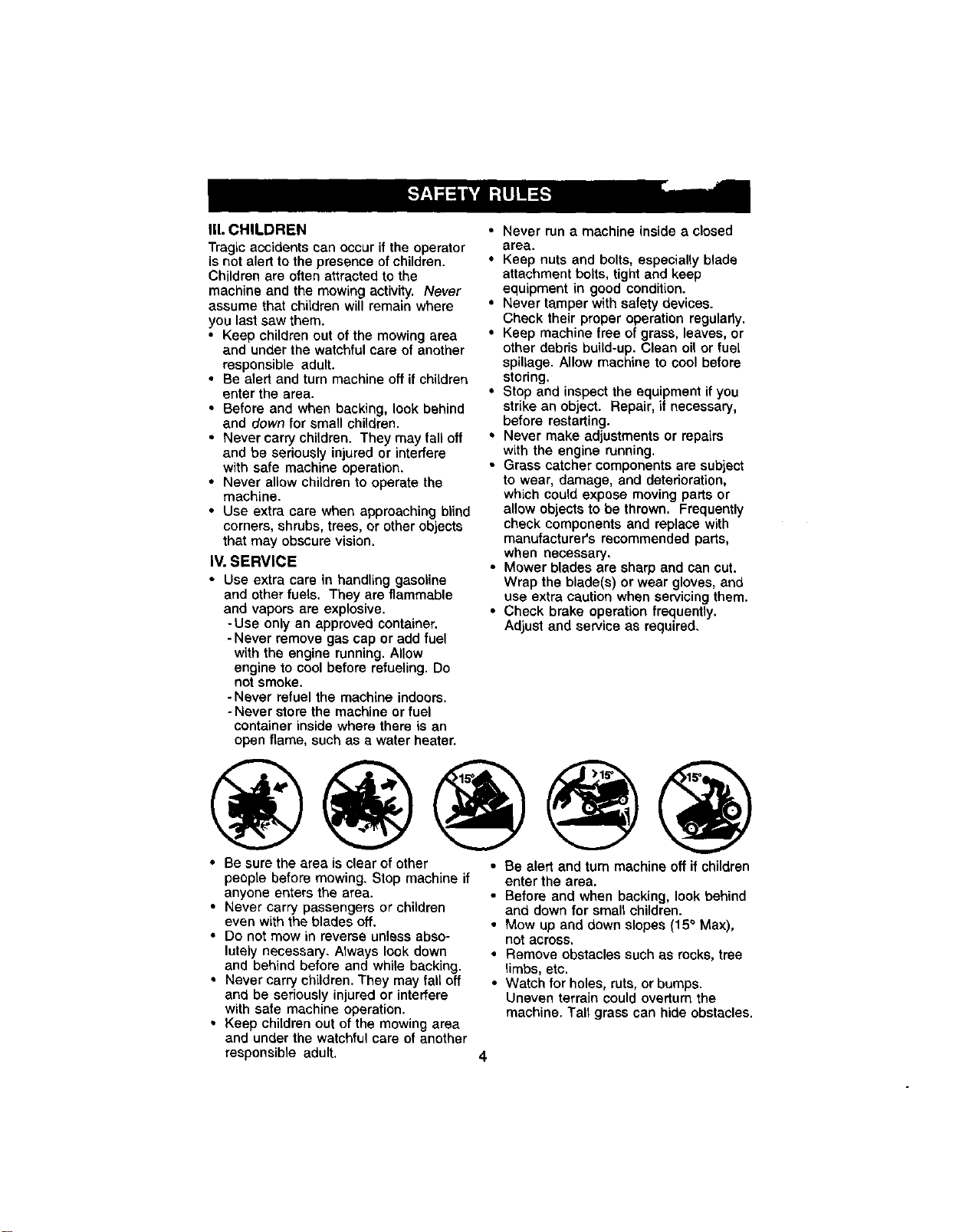
• Mow up and down slopes (15° Max),
not across,
• Remove obstacles such as rocks, tree
limbs, etc.
• Watch for holes, ruts, or bumps.
Uneven terrain could overturn the
machine. Tall grass can hide obstacles.
4

• Use slow speed. Choose a low gear so
that you will not have to stop or shift
while on the slope.
• Avoid starting or stopping on a slope. If
tires lose traction, disengage the
blades and proceed slowly straight
down the slope.
• If machine stops while going uphill,
disengage blades, shift into reverse
and back down slowly.
• Do not turn on slopes unless neces-
sary, and then, turn slowly and gradu-
ally downhill, if possible.
_,Look for this symbol to point out
important safety precautions. It means
CAUTION!!! BECOME ALERT!!! YOUR
SAFETY IS INVOLVED.
_,CAUTION: In order to prevent acci-
dental starting when setting up, trans-
porting, adjusting or making repairs,
always disconnect spark plug wire and
place wire where it cannot contact spark
plug.
_,CAUTION: Do not coast down a hill in
neutral, you may lose control of the
tractor.
_I,CAUTION: Tow only the attachments
that are recommended by and comply
with specifications of the manufacturer of
your tractor. Use common sense when
towing. Operate only at the lowest
possible speed when on a slope. Too
heavy of a load, while on a stope, is
dangerous. Tires can lose traction with
the ground and cause you to lose control
of your tractor.
AWARNING: Engine exhaust, some of its
constituents, and certain vehicle compo-
nents contain or emit chemicals known to
the State of California to cause cancer
and birth defects or other reproductive
harm.
_WARNING: Battery posts, terminals and
related accessories contain lead and
lead compounds, chemicals known to the
State of California to cause cancer and
birth defects or other reproductive harm.
Wash hands after handling.
5
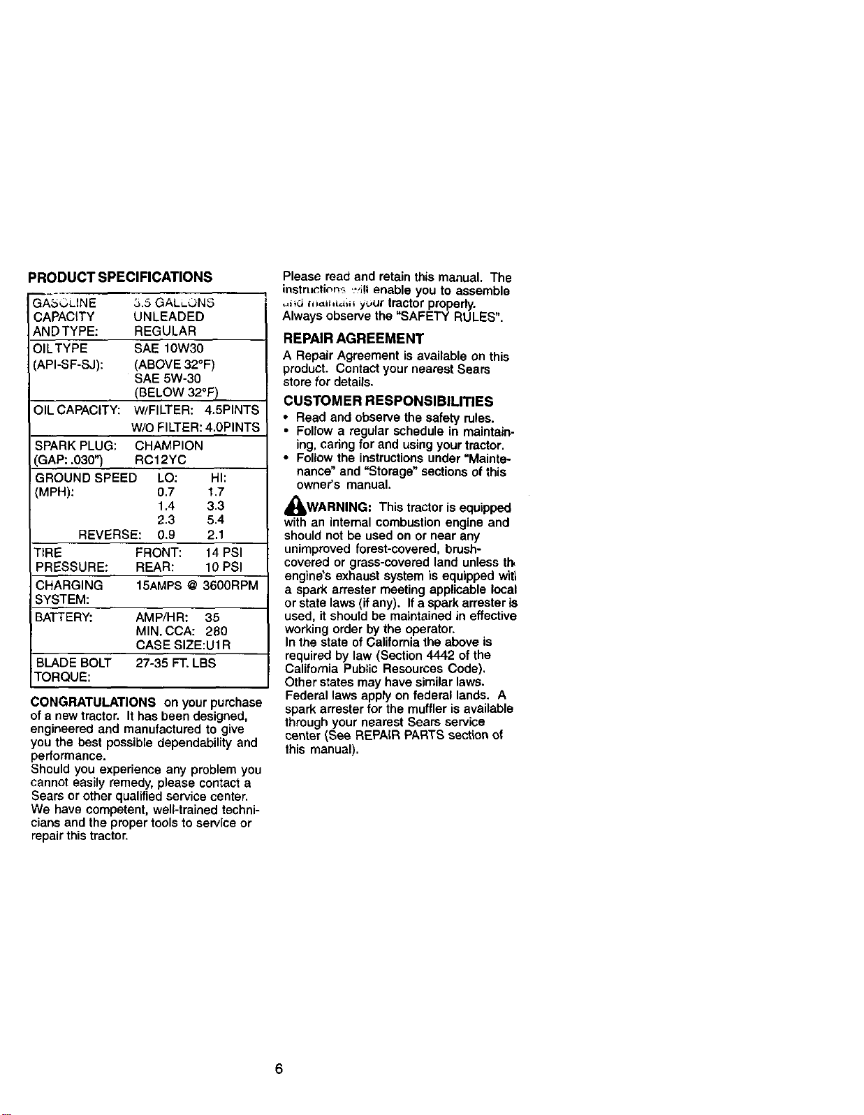
PRODUCT SPECIFICATIONS
GASOLINE 3.5 GALLON_5
CAPACITY UNLEADED
ANDTYPE: REGULAR
OILTYPE SAE 10W30
API-SF-SJ): (ABOVE 32°F)
SAE 5W-30
(BELOW 320F)
OILCAPAClTY: W/FILTER: 4.5PINTS
W/O FILTER: 4.0PINTS
SPARK PLUG: CHAMPION
',GAP: .030") RC12YC
GROUND SPEED LO: HI:
rvlPH): 0.7 1.7
1.4 3.3
2.3 5.4
REVERSE: 0.9 2.1
TIRE FRONT: 14 PSI
PRESSURE: REAR: 10 PSI
CHARGING 15AMPS @ 3600RPM
SYSTEM:
BATTERY: AMP/HR: 35
MIN. CCA: 280
CASE SIZE:U1R
BLADE BOLT 27-35 FT. LBS
TORQUE:
CONGRATULATIONS on your purchase
of a new tractor. It has been designed,
engineered and manufactured to give
you the best possible dependability and
performance.
Should you experience any problem you
cannot easily remedy, please contact a
Sears or other qualified service center.
We have competent, well-trained techni-
cians and the proper tools to service or
repair this tractor.
Please read and retain this manual. The
instruc,tic,nt- ..',ill enable you to assemble
,_i_df,,_ihi,_, y_,ur tractor properly.
Always observe the "SAFETY RULES".
REPAIR AGREEMENT
A RepairAgreementisavailable on this
product. ContactyournearestSears
storefor details,
CUSTOMER RESPONSIBILITIES
• Read and observe the safety rules.
• Follow a regular schedule in maintain-
ing, caring for and using your tractor.
• Follow the instructions under =Mainte-
nance" and "Storage" sections of this
owner's manual.
WARNING: This tractor is equipped
with an internal combustion engine and
should not be used on or near any
unimproved forest-covered, brush-
covered or grass-covered land unless th,
engines exhaust system is equipped witl
a spark arrester meeting applicable local
or state laws (if any). If a spark arrester is
used, it should be maintained in effective
working order by the operator.
In the state of California the above is
required by law (Section 4442 of the
California Public Resources Code).
Other states may have similar laws.
Federal laws apply on federal lands. A
spark arrester for the muffler is available
through your nearest Sears service
center (See REPA{R PARTS section of
this manual).
6
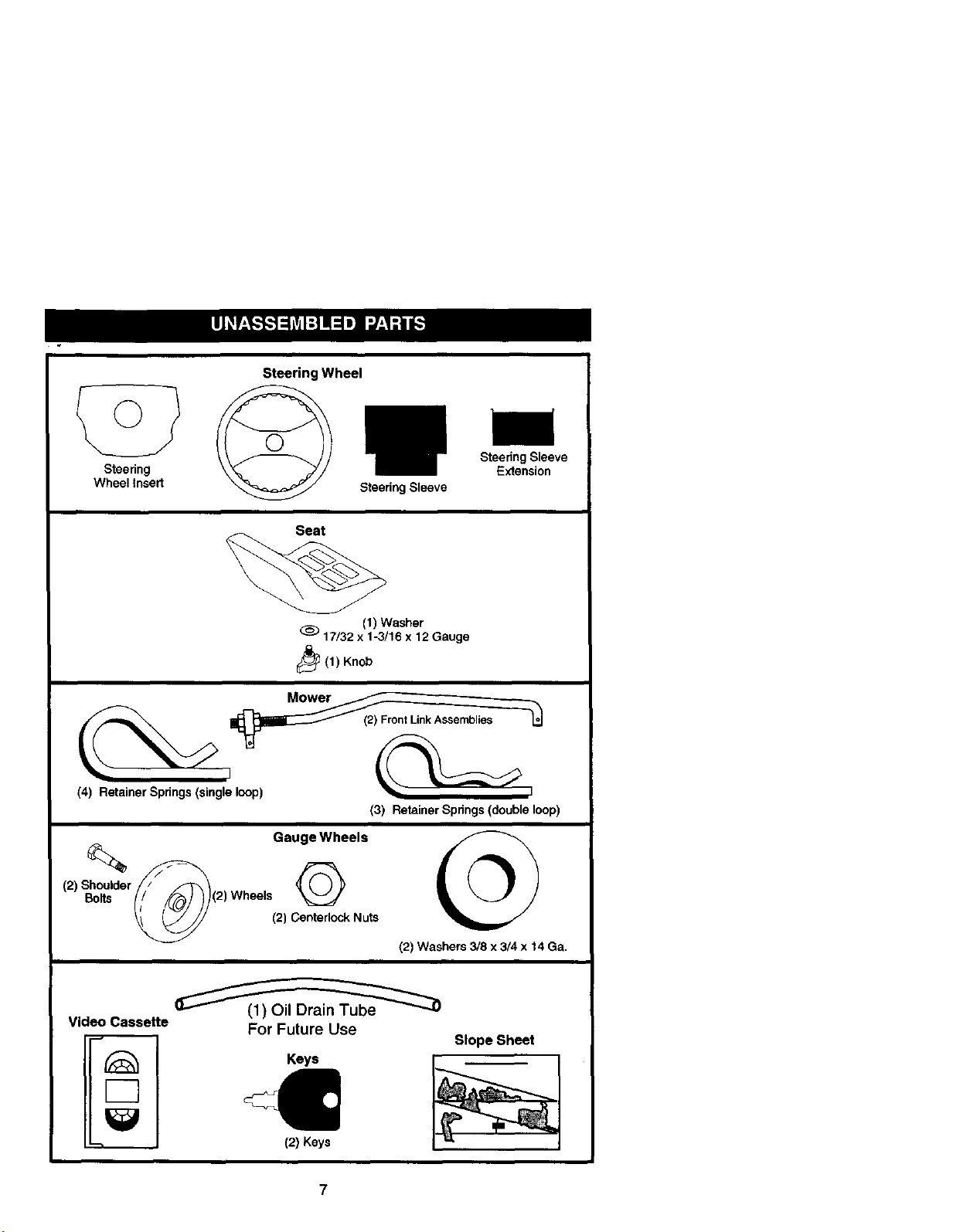
Steering
Wheel Insert
Steering Wheel
Seat
Steenng Sleeve
Steenng Sleeve
E_ension
(1) Washer
(_) 17/32 x 1-3/16 x 12 Gauge
_(1) Knob
(3) Retainer Springs (double loop)
Gauge Wheels
(2_s_o_=_,_= Whee,s
(2) Centerlock Nuts
(2) Washers 3/8 x 3/4 x 14 Ga.
Video Cassette
F-7
For Future Use
Keys
4=
(2)Keys
Slope Sheet
7
Your new tractor has been assembled at the factory with exception of those parts left
unassembled for shipping purposes. To ensure safe and proper operation of your
tractor all parts and hardware you assemble must be tightened securely. Use the
correct tools as necessary to insure proper tightness. Review the video cassette befor,
you begin.
TOOLS REQUIRED FOR ASSEMBLY
A socket wrench set will make assembly
easier, Standard wrench sizes you need
are listed below,
(1) 9/16" wrench (1) Pliers
(1) 1/2"wrench (1) Utility knife
(1) 3/4" socket with
drive ratchet
(1) Tire pressure gauge
When rightor left hand is mentioned in
this manual, it means, from your point of
view, when you are in the operating
position (seated behind the steering
wheel).
TO REMOVETRACTOR FROM
CARTON
UNPACK CARTON
1. Remove all accessible loose parts
and parts cartons from carton.
2. Cut, from topto bottom, along lines on
all four corners of carton, and lay
panels flat.
3. Remove mower and packing materi-
als.
4. Check for any additional loose parts
or cartons and remove.
BEFORE REMOVINGTRACTOR
FROM SKID
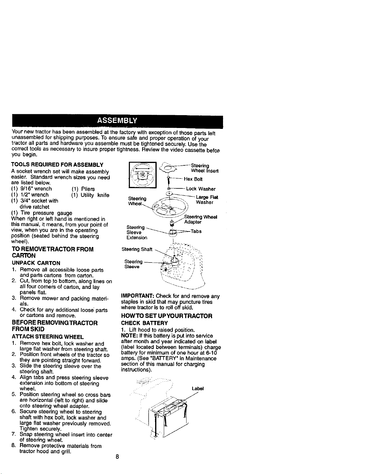
ATTACH STEERING WHEEL
1. Remove hex bolt, _ock washer and
large flat washer from steering shaft.
2. Position front wheels of the tractor so
they are pointing straight forward.
3. Slide the steering sleeve over the
steering shaft.
4. Align tabs and press steering sleeve
extension into bottom of steering
wheel.
5. Position steering wheel so cross bars
are horizontal (left to right) and slide
onto steering wheel adapter.
6. Secure steering wheel to steering
shaft with hex bolt, lock washer and
large flat washer previously removed.
Tighten securely.
7. Snap steering wheel insert into center
of steering wheel.
8. Remove protective materials from
tractor hood and grill.
/_Steering
_.,__ Wheel Insert
Hex Bolt
Lock Washer
Steering __ Laaa_ahFlat
Wheel i_ ' \ Was e
__eedng Wheel
_J Adapter
Steedng
Sleeve _Tabs
Extension I
Steering Shaft
Sleeve
\ \
IMPORTANT: Check for and remove any
staples in skid that may puncture tires
where tractor is to rolloff skid.
HOWTO SET UPYOURTRACTOR
CHECK BATTERY
1. Lift hood to raised position.
NOTE: If this battery is put intoservice
after month and year indicated on label
(label located between terminals) charge
battery for minimum of one hour at 6-10
amps. (See "BATTERY" in Maintenance
section of this manual for charging
instructions).
Label
J
8
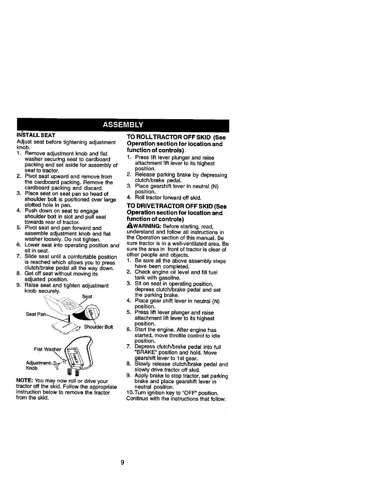
IN'STALL SEAT
Adjust seat before tightening adjustment
knob.
t. Remove adjustment knob and flat
washer securing seat to cardboard
packing and set aside for assembly of
seat to tractor.
2. Pivot seat upward and remove from
the cardboard packing. Remove the
cardboard packing and discard.
3. Place seat on seat pan so head of
shoulder bolt is positioned over large
slotted hole in pan.
4. Push down on seat to engage
shoulder bolt in slot and pull seat
towards rear of tractor.
5. Pivot seat and pan forward and
assemble adjustment knob and flat
washer loosely. Do not tighten.
6. Lower seat into operating position and
sit in seat.
7. Slide seat until a comfortable position
is reached which allows you to press
clutch/brake pedal all the way down.
8. Get off seat without moving its
adjusted position.
9. Raise seat and tighten adjustment
knob securely.
Seat
Seat Pan-.
ShoulderBolt
Flat Washe_. _
.'Jo' tme°t"V"
NOTE: You may now roll or drive your
tractor off the skid. Follow the appropriate
instruction below to remove the tractor
from the skid.
TO ROLLTRACTOR OFF SKID (See
Operation section for location and
function of controls)
1. Pressliftleverplungerand raise
attachmentlift levertoitshighest
position.
2. Release parking brake by depressing
clutch/brake pedal.
3. Place gearshift lever in neutral (N)
position.
4. RoI|tractorforward oftskid.
TO DRIVETRACTOR OFF SKID (See
Operation section for location and
function of controls)
_I;_WARNING: Before starting, read,
understand and follow all instructions in
the Operation section of this manual. Be
sure tractor is in a well-ventilated area. Be
sure the area in front of tractor is clear of
other people and objects.
1. Be sure all the above assembly steps
have been completed.
2. Check engine oil level and fill fuel
tank with gasoline.
3. Sit on seat in operating position,
depress clutch/brake pedal and set
the parking brake.
4. Place gear shift lever in neutral (N)
position.
5. Press lift lever plunger and raise
attachment lift lever to its highest
position.
6. Start the engine. After engine has
started, move throttle control to idle
position.
7. Depress clutch/brake pedal into full
"BRAKE" position and hold. Move
gearshift lever to 1st gear.
8. Slowly release clutch/brake pedal and
slowly drive tractor off skid.
9. Apply brake to stop tractor, set p.arking
brake and place gearshift lever in
neutral position.
10.Turn ignition key to "OFF" position.
Continue with the instructions that follow.
9
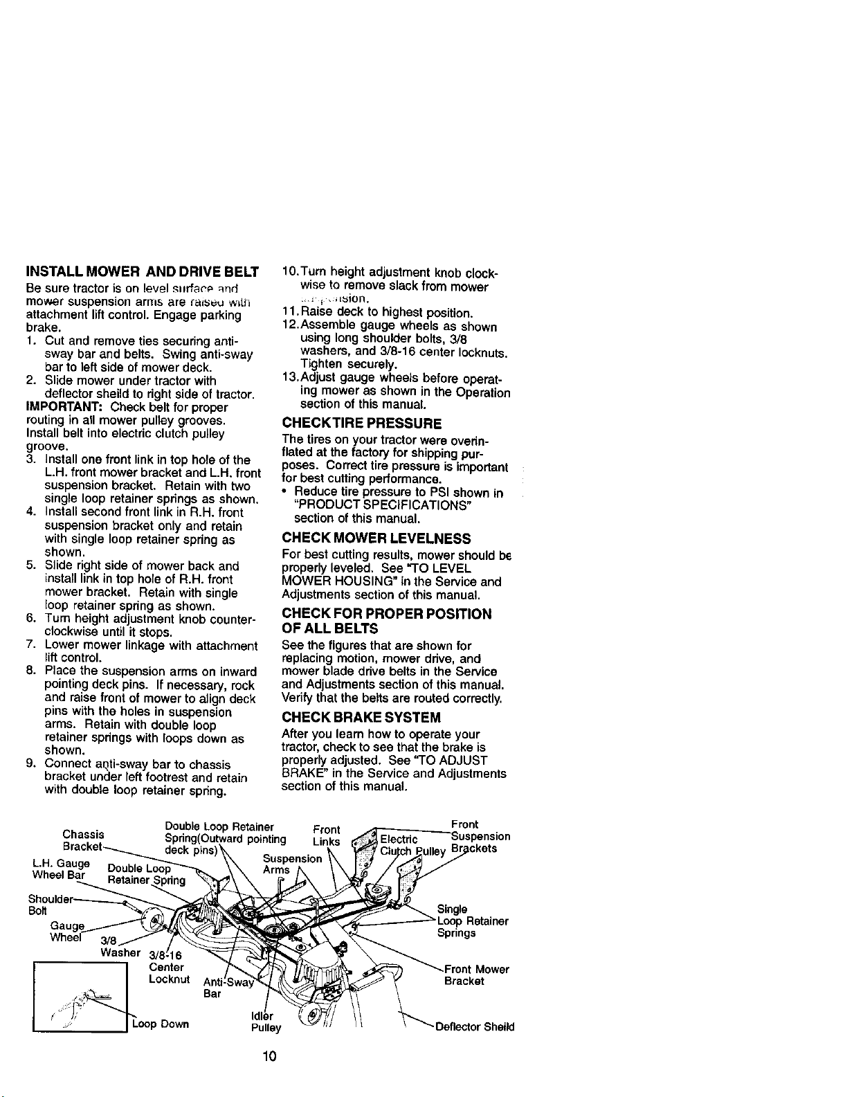
iNSTALL MOWER AND DRIVE BELT
Be sure tractor is on level m_rfae_ -_nd
mo_w_r suspension arnl_, ara (a_ w_t_l
attachment lift control. Engage parking
brake.
1. Cut and remove ties securing anti-
sway bar and belts. Swing anti-sway
bar to left side of mower deck.
2. Slide mower under tractor with
deflector sheild to right side of tractor.
IMPORTANT: Check belt for proper
routing in aU mower pultey grooves.
Install belt into electric clutch pulley
groove.
3. install one front link in top hole of the
L.H. front mower bracket and L.H. front
suspension bracket. Retain with two
single loop retainer springs as shown.
4. Install second front link in R.H. front
suspension bracket only and retain
with single loop retainer spring as
shown.
5. Slide right side of mower back and
install link tn top hole of R.H. front
mower bracket. Retain with single
loop retainer spdng as shown.
6. Tum height adjustment knob counter-
clockwise until it stops.
7. Lower mower linkage with attachment
lift control.
8. Place the suspension arms on inward
pointing deck pins. If necessary, rock
and raise front of mower to align deck
pins with the holes in suspension
arms. Retain with double loop
retainer springs with loops down as
shown.
9. Connect aqti-sway bar to chassis
bracket under left footrest and retain
with double loop retainer spring.
10.Turn height adjustment knob clock-
wise to remove slack from mower
:, i i "_E_iOrl'
11. Raise deck to highest position.
12.Assemble gauge wheels as shown
using long shoulder botts, 3/8
washers, and 3/8-16 center Iocknuts.
Tighten securely.
13.Adjust gauge wheels before operat-
ing mower as shown in the Operation
section of this manual.
CHECKTIRE PRESSURE
The tires on your tractor were overin-
flated at the factory for shipping pur-
poses. Correct tire pressure is important
for best cutting performance.
• Reduce tire pressure to PSI shown in
"PRODUCT SPECIFICATIONS"
section of this manual.
CHECK MOWER LEVELNESS
For best cutting results, mower should bs
properly leveled. See "TO LEVEL
MOWER HOUSING" in the Service and
Adjustments section of this manual.
CHECK FOR PROPER POSITION
OF ALL BELTS
See the figures that are shown for
replacing motion, mower ddve, and
mower blade drive belts in the Service
and Adjustments section of this manual.
Verify that the betts are routed correctly.
CHECK BRAKE SYSTEM
After you learn how to operate your
tractor, check to see that the brake is
properly adjusted. See "TO ADJUST
BRAKE" in the Service and Adjustments
section of this manual
Front
Double Loop Retainer Front - •
Chassis Spdng(Outwardpointing Links ,,_._E!e?tric .. _usp_ns,on
Bracket_ deck pins)_. ! "t,_' Clutch..,PulleyD_._.....
LH Gauge _ - \\ Suspension \ I ._ //,_
'" DoubleLoop_'--k_ \\ Arms iX ,_J_ / '_'_J
Wheel B_....._iner.._ng \'___ __[,/
Shoulder _ "_,_ _ _' _ Sinole
Bo, _¢__ __gpRetainer
Gauge1....-----"_ 'k._\__ _ Springs
Wheel 3/8/ /r __,_'_:_ ,_
I Center 7_'_-_ "_ _ _ _Front Mower
I I Locknut Anf_Sway_,_ _ _" Bracket
I . _ or Sheild/ I; Idler
lO
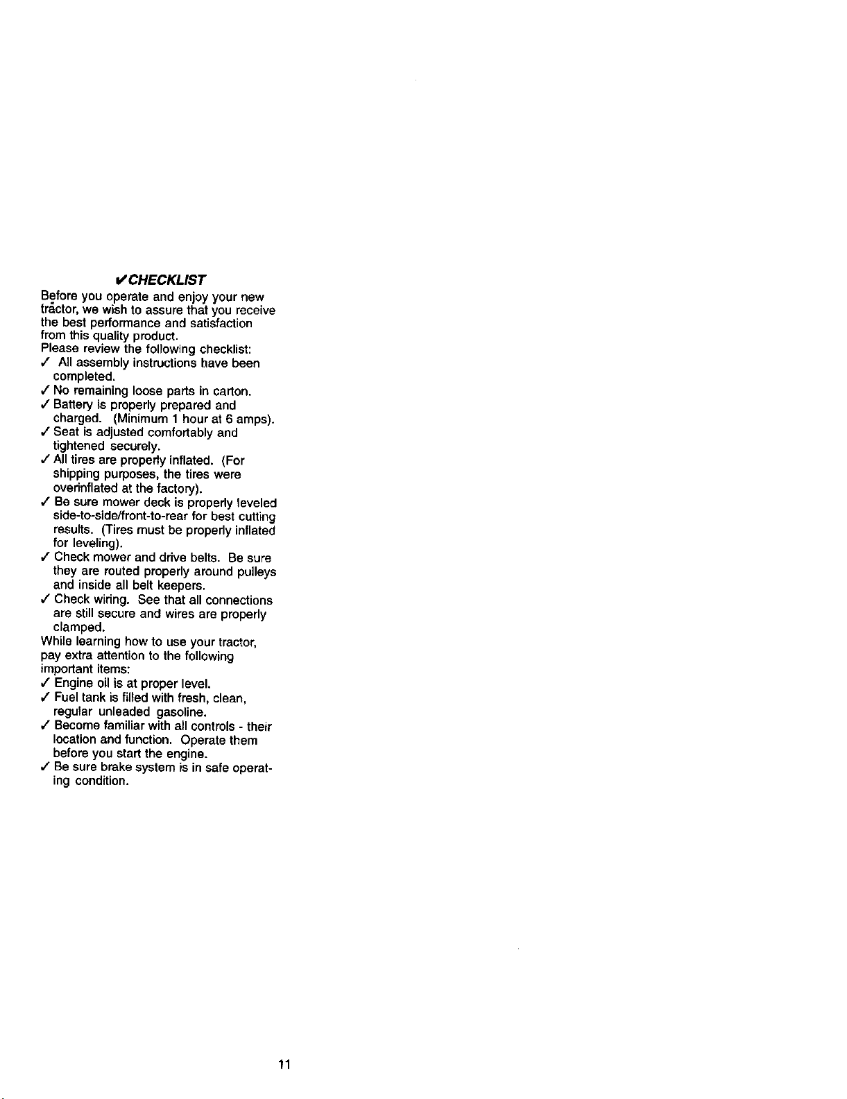
V' CHECKLIST
Before you operate and enjoy your new
_r_ctor, we wish to assure that you receive
the best performance and satisfaction
from this quality product.
Please review the following checklist:
J All assembly instructions have been
completed.
J No remaining loose parts in cation.
J Battery is properly prepared and
charged. (Minimum 1 hour at 6 amps).
J Seat is adjusted comfortably and
tightened securely.
,f All tires are properly inflated. (For
shipping purposes, the tires were
overinflated at the factory).
,/Be sure mower deck is properly leveled
side-to-side/frent-to-rear for best cutting
results. (Tires must be properly inflated
for leveling).
,f Check mower and drive belts. Be sure
they are routed properly around pulleys
and inside all belt keepers.
J Check wiring. See that all connections
are still secure and wires are properly
clamped.
While learning how to use your tractor,
pay extra attention to the following
important items:
b" Engine oil is at proper level.
,/Fuel tank is filled with fresh, clean,
regular unleaded gasoline.
,/Become familiar with all controls - their
location and function. Operate them
before you start the engine.
,/Be sure brake system is in safe operat-
ing condition.
11
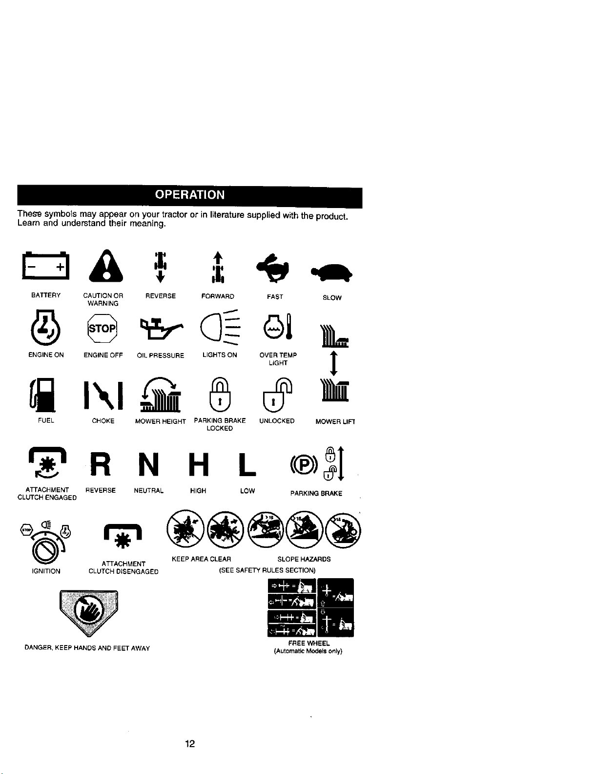
These symbols may appear on your tractor or in literature supplied with the product.
Learn and understand their meaning.
A. =
BATTERY CAUTION OR
WARNING
ENGINE ON ENGINE OFF
REVERSE FORWARD FAST SLOW
FUEL CHOKE
OIL PRESSURE LIGHTS ON OVER TEMP _1_
!
LIGHT
MOWER HEIGHT PARKING BRAKE UNLOCKED MOWER LIFt
LOCKED
_r_'=R N H L
ATTACHMENT REVERSE NEUTRAL HIGH LOW
CLUTCH ENGAGED
PARKING BRAKE
ATTACHMENT KEEP AREA CLEAR SLOPE HAZARDS
IGNITION CLUTCH DISENGAGED (SEE SAFETY RULES SECTION)
DANGER, KEEPHANDSANDFEETAWAY
12
EREEWHEEL
(Automatic Mode_ only)
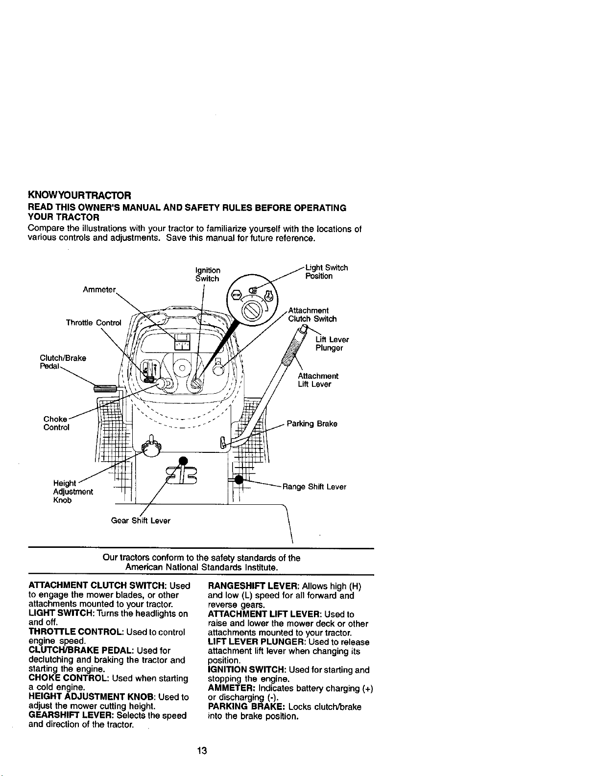
KNOWYOURTRACTOR
READ THIS OWNER'S MANUAL AND SAFETY RULES BEFORE OPERATING
YOUR TRACTOR
Comparethe illustrationswithyourtractortofamiliarizeyourselfwiththe locationsof
variouscontrolsandadjustments,Save this manual forfuturereference.
Ignition
Switch Position
Ammeter
Attachment
Throttle Control Switch
Clutch/Brake
Plunger
Attachment
Lift Lever
Control
,Brake
Adjustment
Knob
/
Gear Shift Lever
\
Our tractorsconformtothesafetystandardsofthe
AmericanNationalStandardsInstitute.
ATTACHMENT CLUTCH SWITCH: Used
to engage the mower blades, or other
attachments mounted to your tractor.
LIGHT SWITCH: Turns the headlights on
and off.
THRO'I'FLE CONTROL: Used to control
engine speed.
CLUTCH/BRAKE PEDAL: Used for
declutching and braking the tractor and
starting the engine.
CHOKE CONTROL: Used when starting
a cold engine.
HEIGHT ADJUSTMENT KNOB: Used to
adjust the mower cutting height.
GEARSHIFT LEVER: Selects the speed
and direction of the tractor.
RANGESHIFT LEVER: Allows high (H)
and low (L) speed for all forward and
reverse gears.
ATTACHMENT LIFT LEVER: Used to
raise and lower the mower deck or other
attachments mounted to your tractor.
LIFT LEVER PLUNGER: Used to release
attachment lift lever when changing its
position.
IGNITION SWITCH: Used for starting and
stopping the engine.
AMMETER: Indicates battery charging (+)
or discharging (-).
PARKING BRAKE: Locks clutch/brake
into the brake position.
13
L
The operation of any tractor can result in foreign objects thrown into the
eyes, which can result in severe eye damage. Always wear safety
!
glasses or eye shields while operating your tractor or performing any
adjustments or repairs. We recommend a wide vision safety mask over
spectac|es or standard safety glasses.
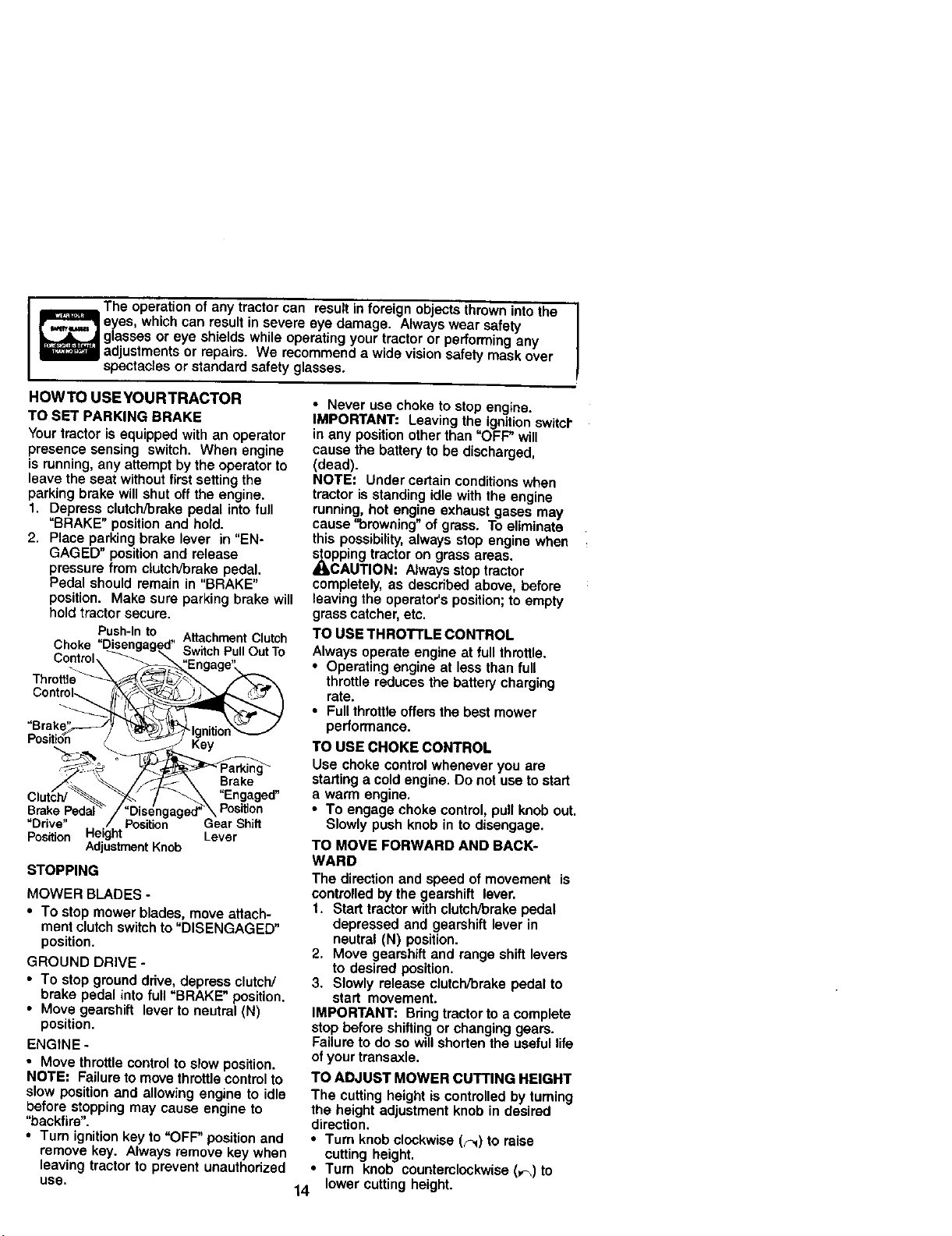
HOWTO USEYOURTRACTOR
TO SET PARKING BRAKE
Your tractor is equipped with an operator
presence sensing switch. When engine
is running, any attempt by the operator to
leave the seat without first setting the
parking brake will shut off the engine.
1. Depress clutch/brake pedal into full
"BRAKE" position and hold.
2. Place parking brake lever in "EN-
GAGED" position and release
pressure from clutch/brake pedal.
Pedal should remain in "BRAKE"
position. Make sure parking brake will
hold tractor secure.
Push-In to Attachment Clutch
Choke SwitchPullOutTo
Controh
Key
Brake
"Engaged"
Brake Peda Position
"Drive" ' Shift
PosKton Lever
Adjustment Knob
STOPPING
MOWER BLADES -
• To stop mower blades, move attach-
ment clutch switch to "DISENGAGED"
position.
GROUND DRIVE -
• To stop ground drive, depress clutch/
brake pedal into full "BRAKE" position.
• Move gearshift lever to neutral (N)
position.
ENGINE -
• Move throttle control to slow position.
NOTE; Failure to move throttle control to
slow position and allowing engine to idle
before stopping may cause engine to
"backfire".
• Turn ignition key to "OFF" position and
remove key. Always remove key when
leaving tractor to prevent unauthorized
use,
• Never use choke to stop engine.
IMPORTANT: Leaving the ignition switcl"
in any position other than "OFF" will
cause the battery to be discharged,
(dead).
NOTE: Under certain conditions when
tractor is standing idle with the engine
running, hot engine exhaust gases may
cause "browning" of grass. To eliminate
this possibility, always stop engine when
stopping tractor on grass areas.
_I_CAUTION: Always stop tractor
completely, as described above, before
leaving the operator's position; to empty
grass catcher, etc.
TO USE THROTTLE CONTROL
Always operate engine at full throttle.
• Operating engine at less than full
throttle reduces the batted/charging
rate.
• Full throttle offers the best mower
performance.
TO USE CHOKE CONTROL
Use choke control whenever you are
starting a cold engine. Do not use to start
a warm engine.
• To engage choke control, pull knob out.
Slowly push knob in to disengage.
TO MOVE FORWARD AND BACK-
WARD
The direction and speed of movement is
controlled by the gearshift _ever.
t. Start tractor with clutch/brake pedal
depressed and gearshift lever in
neutral (N) position.
2. Move gearshift and range shift levers
to desired position.
3. Slowly release clutch/brake pedal to
start movement,
IMPORTANT: Bring tractor to a complete
stop before shifting or changing gears.
Failure to do so will shorten the useful life
of your transaxle.
TO ADJUST MOWER CUTTING HEIGHT
The cutting height is controlled by turning
the height adjustment knob in desired
direction.
• Turn knob clockwise (F,q)to raise
cutting height.
• Turn knob counterclockwise (_,)to
14 lower cutting height.
Thecutting height range is approximately
1-1/2" to 4-1/2". The heights are mea-
sdred from the ground to the blade tip
with the engine not running. These
heights are approximate and may vary
depending upon soil conditions, height of
grass and types of grass being mowed.
• The average lawn should be cut to
approximately 2-1/2 inches during the
cool season and to over 3 inches
during hotmonths. For healthier and
better looking lawns, mow often and
after moderate growth.
• For best cutting performance, grass
over 6 inches In height should be
mowed twice. Make the first cut
relatively high; the second to desired
height.
TO ADJUST GAUGE WHEELS
Gauge wheels are properly adjusted
when they are slightly off the ground
when mower is at the desired cutting
height in operating position. Gauge
wheels then keep the deck in proper
position to help prevent scalping in most
terrain conditions.
NOTE: Adjust gauge wheels with tractor
on a flat level surface.
1. Adjust mower to desired cutting
height.
2. Lower mower with lift control. Re-
move rear retainer spdng and clevis
pin which secure each gauge wheel.
3. Lower gauge wheels lo ground.
Raise gauge wheels slightly to align
holes in bracket and gauge wheel bar
and insert clevis pins. Gauge wheels
should be slightly off the ground.
4. Replace retainer springs into clevis
pins.
Retainer Clevis Pin/r
Spring_-_-.-.-.-.-.-.-.-._0_ _
Gauge _ "E_,_"_////_T_."_
Wheel ii 6¢L ijZZIIf ;i
Gauge_/'_ '_
Wheel Brac'ket_.._
TO OPERATE MOWER
Your tractor is equipped with an operator
presence sensing switch. Any attempt by
the operator to leave the seat with the
engine running and 1he attachment clutch
engaged will shut off the engine.
1. Select desired height of cut.
2. Lower mower with attachment lift
control.
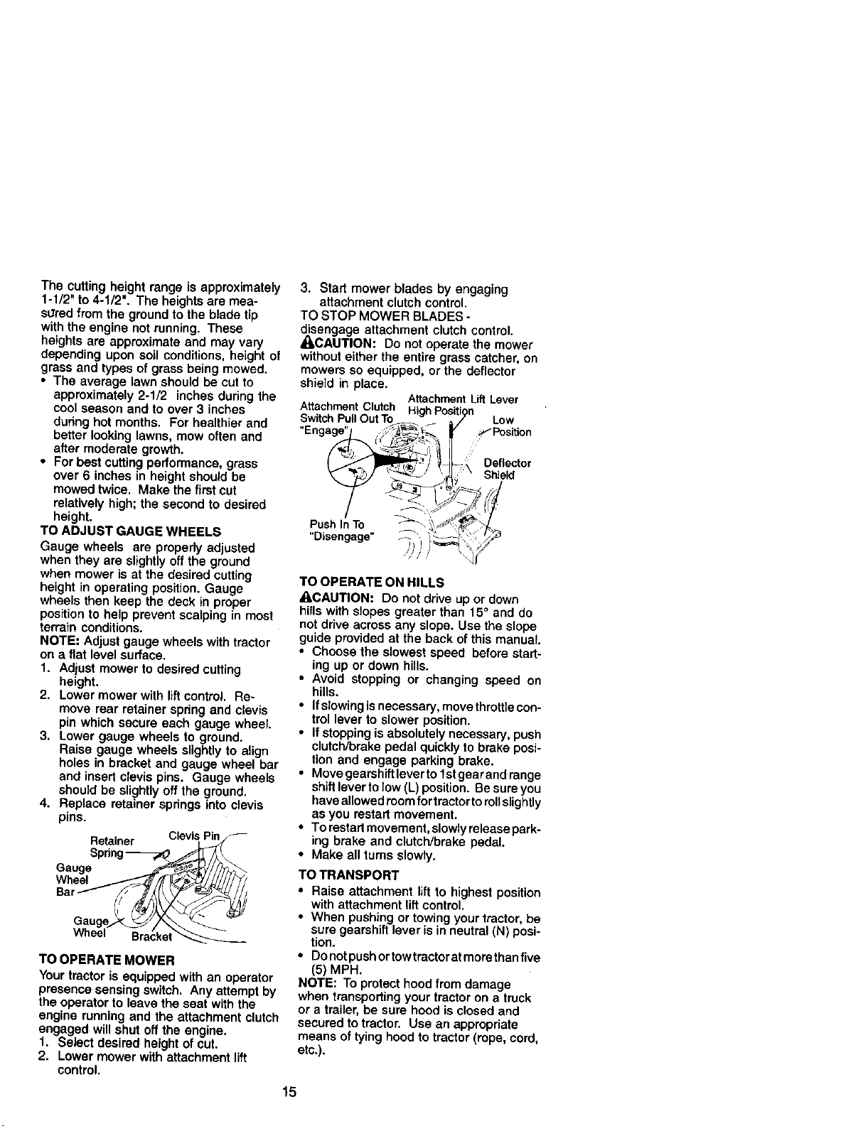
3. Start mower blades by engaging
attachment clutch control.
TO STOP MOWER BLADES -
disengage attachment clutch control,
_CAUTION: Do not operate the mower
without either the entire grass catcher, on
mowers so equipped, or the deflector
shield in place,
Attachment Lift Lever
AttachmentClutch Hlah Position
SwitchPullOutTo_ / Low
"Engage"J ,_,_._ _ _' _-"Position
Push In/ TO _\ >:/" _%
"Disengage" _ i '_--_. :: i,_
TO OPERATE ON HILLS
_I_CAUTION: Do not drive up or down
hills with slopes greater than 150 and do
not drive across any slope. Use the slope
guide provided at the back of this manual.
• Choose the slowest speed before start-
ing up or down hills.
• Avoid stopping or changing speed on
hills.
• If slowing isnecessary, move throttle con-
trol laver to slower position.
• If stopping is absolutely necessary, push
clutch/brake pedal quickly to brake posi-
tion and engage parking brake.
• Move gearahi_t lever to1st gear and range
shift lever to low (L) position. Be sure you
have allowed roomfor tractor to rollslightly
as you restart movement.
• To restart movement, slowlyrelease park-
ing brake and clutch/brake pedal,
• Make all turns slowly.
TO TRANSPORT
• Raise attachment lift to highest position
with attachment liftcontrol.
• When pushing or towing your tractor, be
sure gearshift lever is in neutral (N) posi-
tion.
• Do notpush ortowtrector at morethan five
(5) MPH.
NOTE: To protect hood from damage
when transporting your tractor on a truck
or a trailer, be sure hood is closed and
secured to tractor. Use an appropriate
means of tying hood to tractor (rope, cord,
etc.).
15
TOWING CARTS AND OTHER ATTACH-
MENTS
Tow only the attachments that are
recommended by and comply with
specifications of the manufacturer of your
tractor. Use common sense when towing.
Too heavy of a load, while on a slope, is
dangerous. Tires can lose traction with
the ground and cause you to lose control
of your tractor.
BEFORE STARTING THE ENGINE
CHECK ENGINE OIL LEVEL
The engine in your tractor has been
shipped, from the factory, already fiifed
with summer weight oil.
1. Check engine oil with tractor on level
ground.
2. Unthraad and remove oil fill cap/
dipstick; wipe oil off. Reinsert the
dipstick into the tube and rest oil fill
cap on the tube. Do not thread the
cap onto the tube. Remove and read
oil level. If necessary, add oil until
"FULL" mark on dipstick is reached.
Do not overfill.
• For cold weather operation you should
change oil for easier starting _See "OIL
VISCOSITY CHART" in the Mainte-
nance section of this manuel).
• To change engine oil, see the Mainte-
nance section in this manuel.
ADD GASOLINE
• Fill fuel tank. Use fresh, clean, regular
unleaded gasoline with a minimum of
87 octane. (Use of leaded gasoline
will increase carbon and lead oxide
deposits and reduce valve life). Do not
mix oil with gasoline. Purchase fuel in
quantities that can be used within 30
days to assure fuel freshness.
IMPORTANT: When operating in
temperatures below 32°F(0°C), use fresh,
clean winter grade gasoline to help
insure good cold weather starting.
_,WARNING: Experience indicates that
elcoho_ blended fuels (called gasoho_ or
using ethanol or methanol) can attract
moisture which leads to separation and
formation of acids during storage. Acidic
gas can damage the fuel system of an
engine while in storage. To avoid engine
problems, the fuel system should be
emptied before storage of 30 days or
longer. Drain the gas tank, start the
engine and let it run until the fuel lines
and carburetor are empty. Use fresh fuel
next season. See Storage Instructions fo
additional information. Never use engin(
or carburetor cleaner products in the fuel
tank or permanent damage may occur.
_,CAUTION: Fillto bottom of gas tank
filler neck. Do not overfill. Wipe off any
spilled oil or fuel. Do not store, spill or
use gasoline near an open flame.
TO START ENGINE
When startingtheengine for the firsttime or if
the engine has run out offuel, itwilltake extra
crankincj time to move fuel from the tank to
the engine.
1. Sit on seat in operating position,
depress clutch/brake pedal and set
parking brake.
2. Place gear shift lever in neutral (N)
position.
3. Move attachment clutch to "DISEN-
GAGED" position.
4. Move throttle control to fast position
5. Pull choke control out for a cold
engine start attempt. For a warm
engine start attempt the choke control
may not be needed.
NOTE: Before starting, read the warm and
cold starting prccedures below.
6. Insert key into ignition and turn key
clockwise to "START" position and
release key as soon as engine starts.
Do not run starter continuously for
more than fifteen seconds per minute.
Ifthe engine does not start alter
several attempts, push choke control
in, wait a few minutes and try again. If
engine still does not start, pull the
choke control out and retry.
WARM WEATHER STARTING (50° F and
above)
7. When engine starts, slowly push
choke control in until the engine
begins to run smoothly. If the engine
starts to run roughly, pull the choke
control out slightly for a few seconds
and then continue to push the control
in slowly.
16
• The attachments and ground ddve can
now be used. If the engine does not
-accept the load, restart the engine and
allow it to warm up for one minute
using the choke as described above.
COLD WEATHER STARTING (50° F and
below)
7. When engine starts, slowly push
choke control in until the engine
begins to run smoothly. Continue to
push the choke control in small steps
allowing the engine to accept small
changes in speed and load, until the
choke control is fully in. If the engine
starts to run roughly, pull the choke
control out slightly for a few seconds
and then continue to push the control
in slowly. This may require an engine
warm-up period from several seconds
to several minutes, depending on the
temperature.
• The attachments can be used during
the engine warm-up period and may
require the choke control be pulled out
slightly.
NOTE= If at a high altitude (above 3000
feet) or in cold temperatures (below 32 F)
the carburetor fuel mixture may need to
be adjusted for best engine performance.
See "TO ADJUST CARBURETOR" in the
Service and Adjustments section of this
manual.
MOWlNGTIPS
• Tire chains cannot be used when the
mower housing is attached to tractor.
• Mower should be properly leveled for
best mowing performance. See "TO
LEVEL MOWER HOUSING" in the
Service and Adjustments section of this
manual.
• Use the runner on the right side of the
mower as a guide. The blade cuts
approximately an inch outside the
runner.
• The left hand side of mower should be
used for trimming.
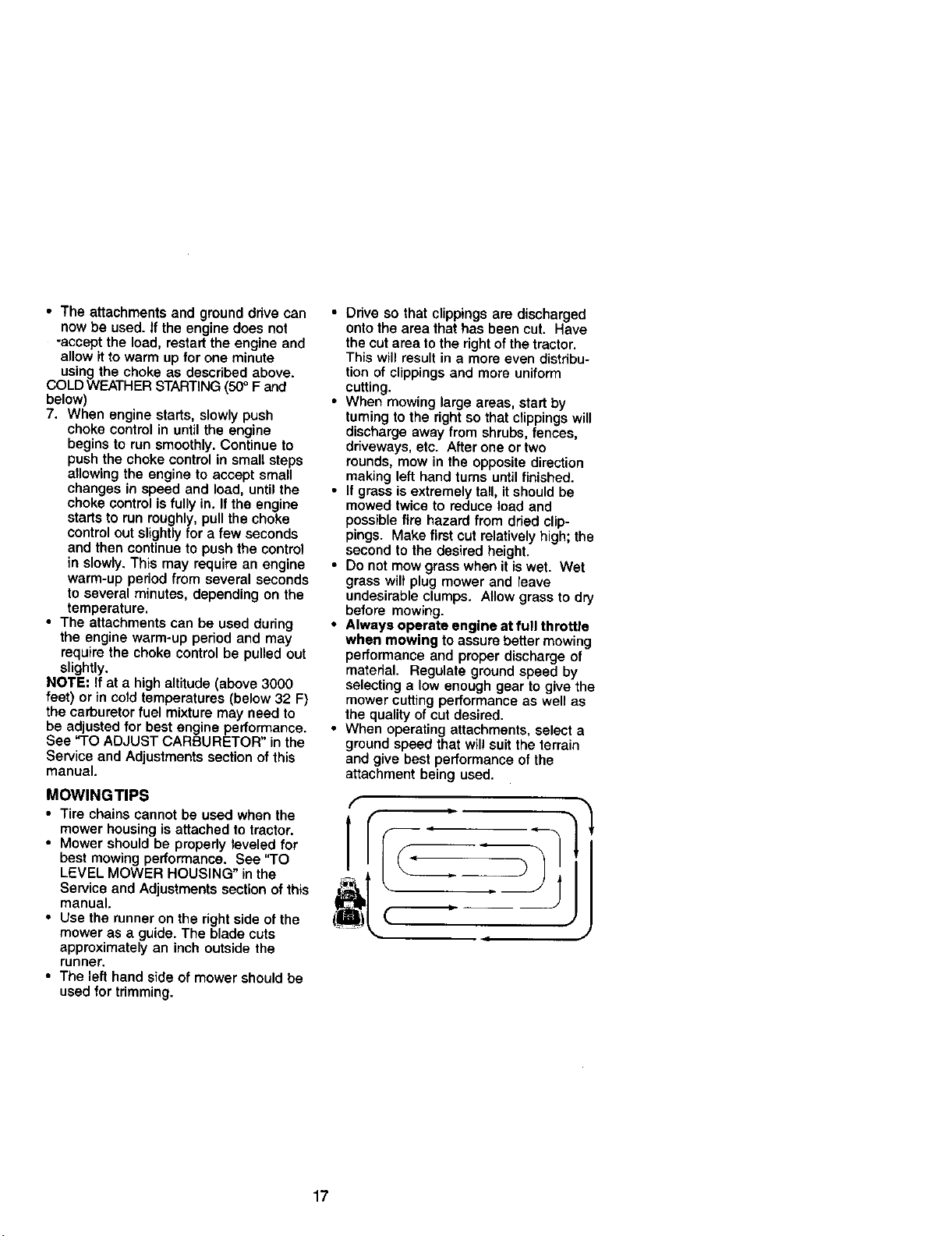
• Ddve so that clippings are discharged
onto the area that has been cut. Have
the cut area to the right of the tractor.
This will result in a more even distribu-
tion of clippings and more uniform
cutting.
• When mowing large areas, start by
tuming to the right so that clippings will
discharge away from shrubs, fences,
driveways, etc. After one or two
rounds, mow in the opposite direction
making left hand turns until finished.
• If grass is extremely tall, it should be
mowed twice to reduce load and
possible fire hazard from dried clip-
pings. Make first cut relatively high; the
second to the desired height.
• Do not mow grass when it is wet. Wet
grass wilt plug mower and leave
undesirable clumps. Allow grass to dry
before mowing.
• Always operate engine at fun throttle
when mowing to assure better mowing
performance and proper discharge of
material. Regulate ground speed by
selecting a low enough gear to give the
mower cutting performance as well as
the quality of cut desired.
• When operating attachments, select a
ground speed that will suit the terrain
and give best performance of the
attachment being used.
[
!
17
"MAINTENANCE SCHEDULE _/_/_'_/:'_/_,/1_
AS YOU COMPLETE _,_¢'_ _'_ _q_" _',_ _._ _
Check Brake Operation _ i tl_
Check Tire PreP,sure I1_ i I_
i CheCk Operator Presence and
T InterlOCk Systems V'
R Check for Loose Fasteners _ 1_7
cA Sharpen/Rep4ace MOWer Blades rl_'4
T Lubrication Chart _ I1_
O CheCk Battery Level
R Clean Battery and Terminals _
ChqJCk Trar_axle Cooling _je
Adjust IBlacNJBelt(s) Tension _s
Adjust Motion Drive Belt(s) Tension _s
CheCk Errgine Oil Level I_ It_
Change Engine Oil 11_1,2,_ I_
E Clean Air Filter ll_z
Clean Air Screen 1_2
iG ' Inspect Muff er/Bp_ k At'ester I_ I
Replace OII Filter (If equipped) 1_12
N' Clean Engine Cooling Fins ! _=
i Replace Spark Plug i ll_ I1_
Replace Air Filter Paper Cartridge _1_=
! Replace Fuel Filter
Change more o_en when opera_ng under a hea W Ioa_ or _n hbgh ambient zer_peratu_ea S. _ _ubpped wl_ adjustable ey_em
2 - Se_e more o_en when o_'_llng m dbrt'/or dusty co_diZ_n_ 6 NOZ r*_ulr_d _ _ped W_ ma_na_.f_e ba_ee/,
3. Jr _uk_p_ w_h oil filter, chenge oil every 5O hour=¸ 7. T_ght_n fron_ e_lo pk,ot boll _ 3_ _._ m_x_mum
4. Ropl_e blado_ more often when mowing in sandy SO_ DO noZoverbehten
GENERAL RECOMMENDATIONS
The warranty on this tractor does not cover
items that have been subjected to operator
abuse or negligence. To receive full value
from the warranty, operator must maintain
tractor as instructed in this manual.
Some adjustments will need to be made
periodically to propedy maintain your
tractor.
All adjustments in the Service and
Adjustments section of this manual should
be checked at least once each season.
• Once a year you should replace the
spark plug, clean or replace air filter, and
check blades end belts for wear, A new
spark plug and clean air filter assure
proper air-fuel mixture and help your
engine run better and last longer.
BEFORE EACH USE
1. Check engine oil level
2. Check brake operation.
3, Check tire pressure.
4. Check operator presence and
interlock systems for proper operation.
5, Check for loose fasteners,
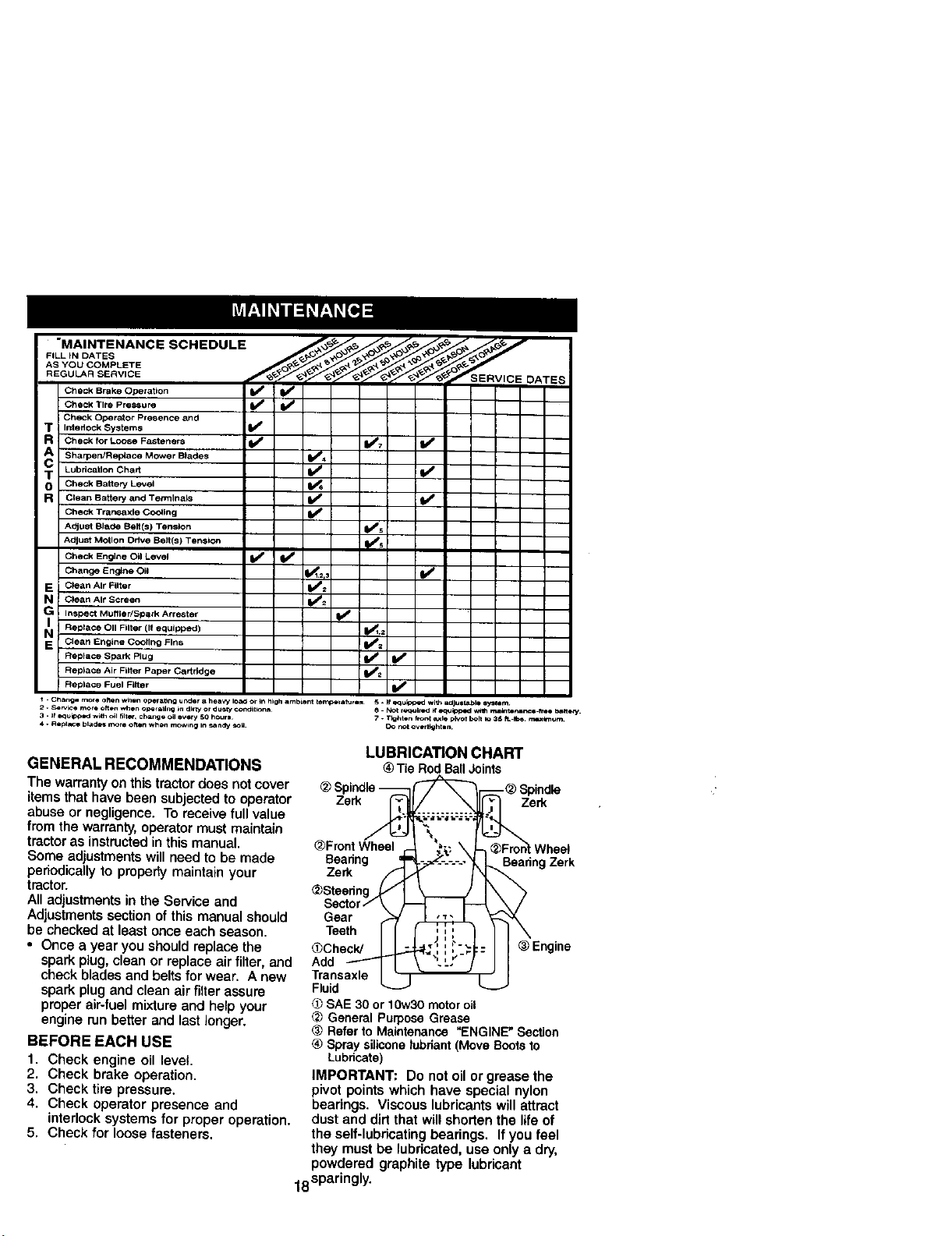
LUBRICATION CHART
® TieRodBallJoints
Spindle
Zerk Zerk
_Fmnt Wheel
Bearing
Zerk
Bearing Zerk
Gear
Teeth
_Check/
Add
Transaxle
Fluid
SAE 30 or 10w30 motor oil
General Purpose Grease
(_ Refer to Maintenance eENGINE" Section
® Spray silicone tubriant (Move Soots to
Lubricate)
IMPORTANT: Do not oil or grease the
pivot points which have special nylon
bearings. Viscous lubricants will attract
dust and dirt that will shorten the life of
the self-lubricating bearings. If you feel
they must be lubricated, use only a dry,
powdered graphite type lubricant
18sparingly.
TRACTOR
Always observe safety rules when
p_rtorming any maintenance.
BRAKE OPERATION
If tractor requires more than six (6) feet
stopping distance at high speed in
highest gear, then brake must be ad-
justed. (See "TO ADJUST BRAKE" in the
Service and Adjustments section of this
manual).
TIRES
• Maintain proper air pressure in all tires
(See "PRODUCT SPECIFICATIONS"
section of this manual).
• Keep tires free of gasoline, oil, or insect
control chemicals which can harm
rubber.
• Avoid stumps, stones, deep ruts, sharp
objects and other hazards that may
cause tire damage.
NOTE: To seal tire punctures and prevent
flat tires due to slow leaks, tire sealant
may be purchased from your local parts
dealer. Tire sealant also prevents tire dry
rot and corrosion.
OPERATOR PRESENCE SYSTEM
Be sure operator presence and interlock
systems are working properly. If your
tractor does not function as described,
repair the problem immediately.
• The engine should not start unless the
clutch/brake pedal is fully depressed
and attachement clutch control is in the
disengaged position.
• When the engine is running, any
attempt by the operator to leave the
seat without first setting the parking
brake should shut off the engine.
• When the engine is running and the
attachment clutch is engaged, any
attempt by the operator to leave the
seat should shut off the engine.
• The attachment ctutch should never
operate unless the operator is in the
seat.
BLADE CARE
For best results mower blades must be
kept sharp. Replace bent or damaged
blades.
BLADE REMOVAL
1. Raise mower to highest position to
allow access to blades.
2. Remove hex bolt, lock washer and flat
washer securing blade.
3. Install new or resharpened blade with
trailing edge up towards deck as
shown.
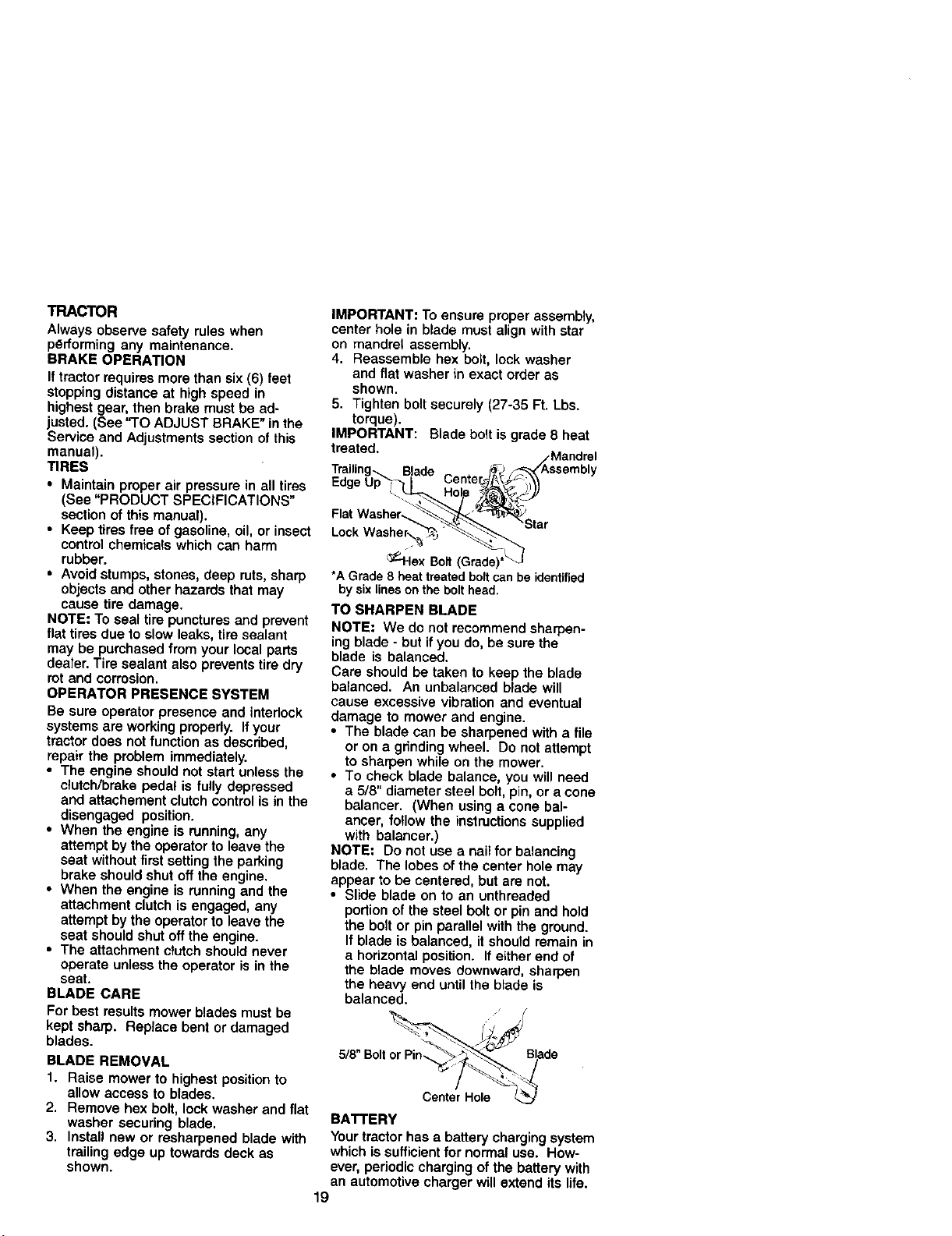
IMPORTANT: To ensure proper assembly,
center hole in blade must align with star
on mandrel assembly.
4. Reassemble hex bolt, lock washer
and flat washer in exact order as
shown.
5. Tighten bolt securely (27-35 Ft. Lbs.
torque).
IMPORTANT: Blade bolt is grade 8 heat
treated.
/.Mandrel
Trailing_ Blade (_-J,_/Assembly
Edge Up !_ I Center_ _,_-i_
Flat Wash__ar
•oc.
_lex Bolt (Grade)*_
•A Grade 8 heattreated bolt can be identified
by sixlines on the belt head.
TO SHARPEN BLADE
NOTE: We do not recommend sharpen-
ing blade - but if you do, be sure the
blade is balanced.
Care should be taken to keep the blade
balanced. An unbalanced blade will
cause excessive vibration and eventual
damage to mower and engine.
• The blade can be sharpened with a file
or on a grinding wheel. Do not attempt
to sharpen while on the mower.
• To check blade balance, you will need
a 5/8" diameter steel bolt, pin, or a cone
balancer. (When using a cone bal-
ancer, fo!low the instructions supplied
with balancer.)
NOTE: Do not use a nail for balancing
blade. The lobes of the center hole may
appear to be centered, but are not.
• Slide blade on to an unthreaded
podion of the steel bolt or pin and hold
the bolt or pin parallel with the ground.
If blade is balanced, it should remain in
a horizontal position. If either end of
the blade moves downward, sharpen
the heavy end until the blade is
balanced.
="Boltor B,ade
Center Hole
BATTERY
Your tractor has a battery charging system
which is sufficient for normal use. How-
ever, periodic charging of the battery with
an automotive charger will extend its life.
19
• Keep batter,/and terminals clean.
• Keep battery bolts tight.
• Keep small vent holes open.
• Recharge at 6-10 amperes for 1 hour.
NOTE: The odginal equipment battery on
your tractor is maintenance free, Do not
attempt to open or remove caps or covers.
Adding or checking level of electrolyte is
not necessary.
TO CLEAN BATTERY AND TERMINALS
Corrosion and dirt on the battery and
terminals can cause the battery to "leak"
power.
1. Remove terminal guard.
2. Disconnect BLACK battery cable first
then RED battery cable and remove
battery from tractor.
3. Rinse the battery with plain water and
dry,
4. Clean terminals and battery cable ends
with wire brush until bright.
5. Coat terminals with grease or petro-
leum jelly.
6. Reinstall battery (See "REPLACING
BATTERY" in the SERVICE AND
ADJUSTMENTS section of this
manual).
V-BELTS
Check V-belts for deterioration and wear
after 100 hours of operation and replace if
necessary, The belts are not adjustable.
Replace belts ifthey begin to slip from
wear,
TRANSAXLE COOLING
Keep transsxle free from build-up of dirt
and chaff which can restrictcooling.
CHECK TRANSAXLE OIL LEVEL
1. Block up rear axle securely.
2, Remove left rear wheel by removing
hub bolts,
3. Remove filler plug from transaxle. Oil
level must be even with plug threads. If
necessary, fill with SAE 30 motor oil,
API SF-SJ. Replace filler plug.
4. Reassemble wheel to hub.
_.°_ TransaxleFiller
Plug
ENGINE
LUBRICATION
Only use high quality detergent oil rated
with API service classification SF-SJ.
Salect the oil's SAE viscosity grade
according to your expected operating
temperature.
SAE VISCOSITY GRAOES
Change the oil after every 50 hours of
operation or at least once a year if the
tractor is not used for 50 hours in one
year.
Check the crankcase oil level before
starting the engine and after each eight
(8) hours of operation. Tighten oil fill cap/
dipstick securely each time you check th_
oil level.
TO CHANGE ENGINE OIL
Determine temperature range expected
before oil change. All oil must meet API
service classification SF-SJ,
• Be sure tractor is on level surface.
• Oil will drain more freely when warm.
• Catch oi! in a suitable container.
1. Remove oil fill cap/dipstick` Be careful
not to allow dirt to enter the engine
when changing oil.
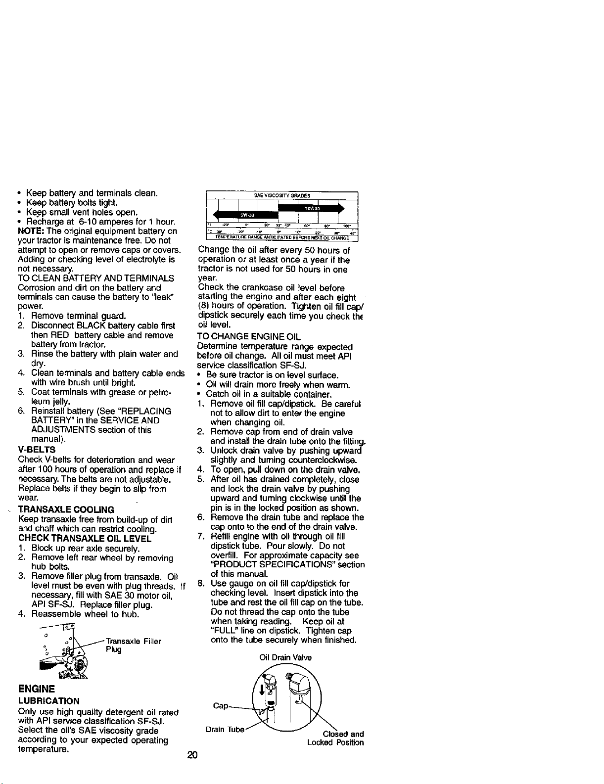
2, Remove cap from end of drain valve
and install the drain tube onto the fitting.
3. Unlock drain valve by pushing upward
slightly and turning counterclockwise.
4. To open, pull down on the drain valve.
5. After oil has drained completely, close
and lock the drain valve by pushing
upward and turning clockwise until the
pin is in the locked position as shown.
6, Remove the drain tube and replace the
cap onto to the end of the drain valve.
7. Refill engine with oil through oi1flit
dipstick tube. Pour slowly. Do not
overfill. For approximate capacity see
"PRODUCT SPECIFICATIONS" section
of this manual.
8. Use gauge on oil fill cap/dipstick for
checking level. Insert dipstick into the
tube and rest the oil fill cap on the tube.
Do not thread the cap onto the tube
when taking reading. Keep oil at
"FULL" line on dipstick, Tighten cap
onto the tube securely when finished.
Oil Drain Valve
DrainTube
2O
Locked Pos_on
CLEAN AIR SCREEN
Air screen must be kept free of dirt and
c_aff to prevent engine damage from
overheating. Clean with a wire brush or
compressed air to remove dirt and
stubborn dried gum fibers.
CLEAN AIR INTAKE/COOLING AREAS
To insure proper cooling, make sure the
grass screen, cooling fins, and other
external surfaces of the engine are kept
clean at all times.
Even 100 hours of operation (more often
under extremely dusty, dirty conditions),
remove the blower housing and other
cooling shrouds. Clean the cooling fins
and external surfaces as necessary.
Make sure the cooling shrouds are
reinstalled.
NOTE: Operating the engine with a
blocked grass screen, dirty or plugged
cooling fins, and/or cooling shrouds
removed will cause engine damage due
to overheating.
AIR FILTER
Your engine will not run properly using a
dirty air filter. Clean the foam pra-cleaner
after every 25 hours of operation or every
season. Service paper cartridge every
100 hours of operation or every season,
whichever occurs first.
Service air cleaner more often under
dusty conditions.
1. Loosen knob and remove cover.
TO SERVICE PRE-CLEANER
2. Slide foam pre-cleaner off cartridge.
3. Wash it in liquid detergent and water.
4. Squeeze it dry in a clean cloth. Allow
it todry.
5. Saturate it in engine oil. Wrap it in
clean, absorbent cloth and squeeze to
remove excess oil.
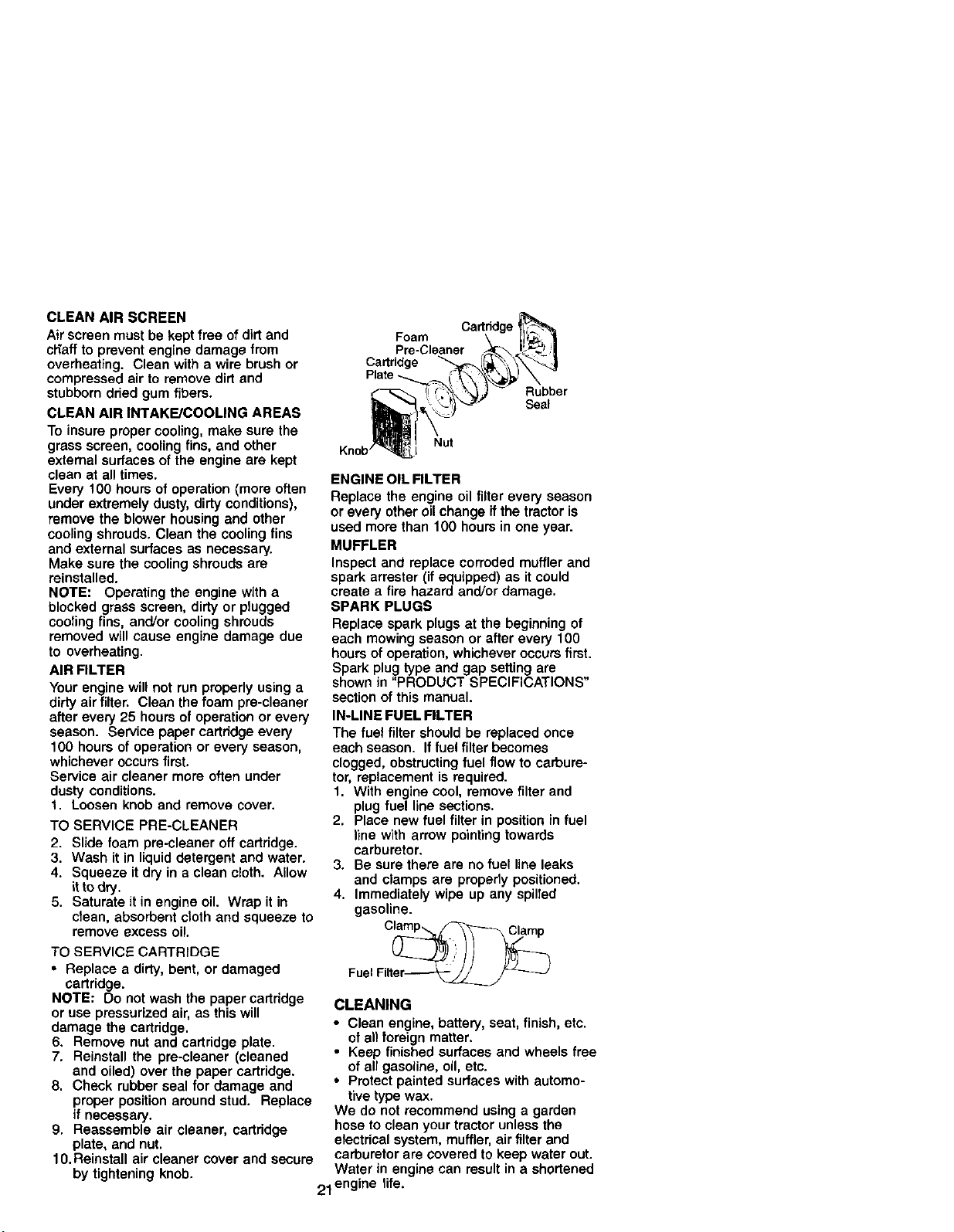
TO SERVICE CARTRIDGE
• Replace a dirty, bent, or damaged
cartridge.
NOTE: Do not wash the paper cartridge
or use pressurized air, as this will
damage the cartridge.
6. Remove nut and cartridge plate.
7. Reinstall the pre-cleaner (cleaned
and oiled) over the paper cartridge.
8. Check rubber seal for damage and
proper position around stud. Replace
if necessary.
9. Reassemble air cleaner, cedridge
plate, and nut.
10. Reinstall air cleaner cover and secure
by tightening knob,
Cartndge
Foam
Pre-Cleaner
Cartridge
Rubber
Seal
Nut
Knob
ENGINE OIL FILTER
Replace the engine oil filter every season
or every other oil change if the tractor is
used more than 100 hours in one year.
MUFFLER
Inspect and replace corroded muffler and
spark arrester (if equipped) as it could
create a fire hazard and/or damage.
SPARK PLUGS
Replace spark plugs at the beginning of
each mowing season or after every 100
hours of operation, whichever occurs first.
Spark plug type and gap setting are
shown in "PRODUCT SPECIFICATIONS"
section of this manual.
IN-LINE FUEL FILTER
The fuel filter should be replaced once
each season. If fuel filter becomes
clogged, obstructing fuel flow to carbure-
tor, replacement is required.
1. With engine cool, remove filter and
plug fuel line sections.
2. Place new fuel filter in position in fuel
line with arrow pointing towards
carburetor.
3. Be sure there are no fuel line leaks
and clamps are prepedy positioned.
4. Immediately wipe up any spilled
gasoline.
Fuel Filter_
CLEANING
• Clean engine, battery, seat, finish, etc.
of all foreign matter,
• Keep finished surfaces and wheels free
of all gasoline, oil, etc.
• Protect painted surfaces with automo-
tive type wax.
We do not recommend using a garden
hose to clean your tractor unless the
electrical system, muffler, air filter and
carburetor are covered to keep water out.
Water in engine can result in a shortened
21 engine life.
CAUTION: BEFORE PERFORMING ANY SERVICE OR ADJUSTMENTS:
1. Depress clutch/brake pedal fully and set parking brake.
2. Place gearshift lever in neutral (N) position.
3. Place attachment clutch in "DISENGAGED" position.
4. Turn ignition key "OFF" and remove key.
5. Make sure the blades and all moving parts have completely stopped.
6. Disconnect spark plug wire from spark plug and place wire where it cannot
come in contact with plug.
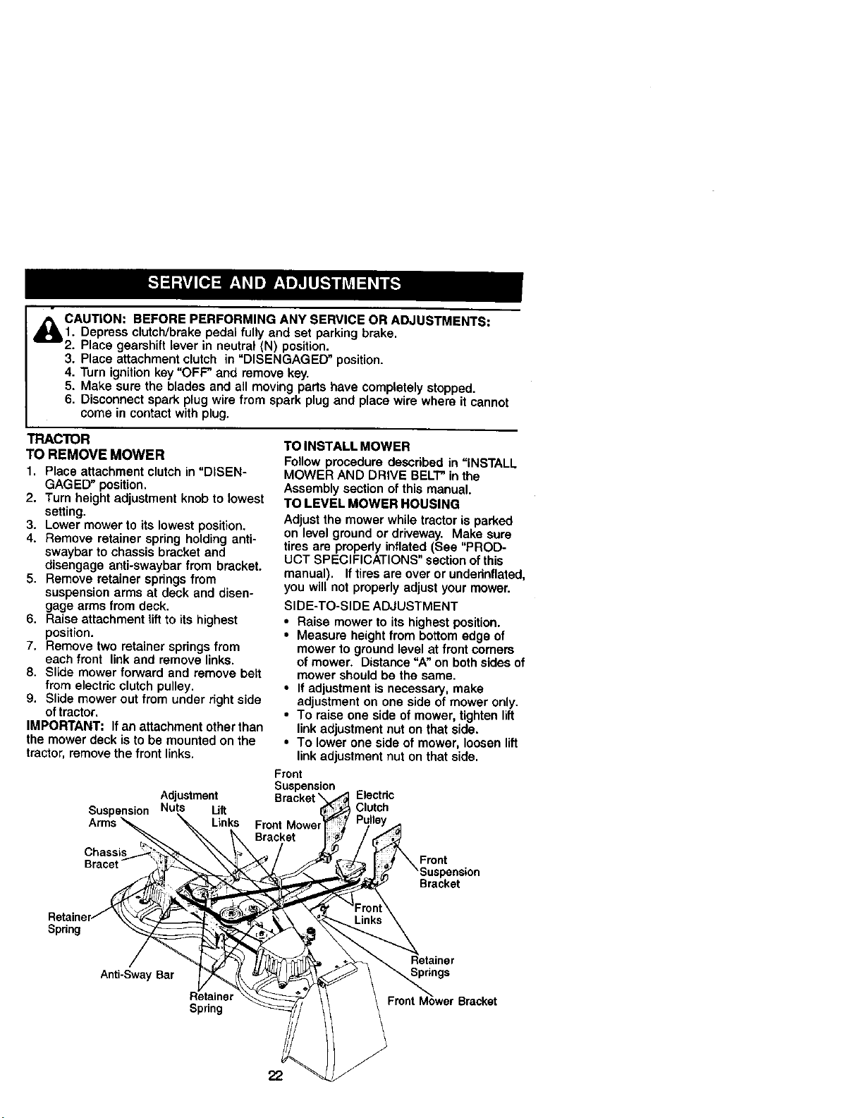
TRACTOR
TO REMOVE MOWER
1. Place attachment clutch in "DISEN-
GAGED" position.
2. Turn height adjustment knob to lowest
setting.
3. Lower mower to its lowest position.
4. Remove retainer spring holding anti-
swaybar to chassis bracket and
disengage anti-swaybar from bracket.
5. Remove retainer springs from
suspension arms at deck and disen-
gage arms from deck.
6. Raise attachment lift to its highest
position.
7. Remove two retainer springs from
each front link and remove links.
8. Slide mower forward and remove belt
from electric clutch pulley.
9. Slide mower out from under right side
of tractor.
IMPORTANT: If an attachment other than
the mower deck is to be mounted on the
tractor, remove the front links.
Adjustment
Suspension Nuts Lift
Links
TO INSTALL MOWER
Follow procedure described in "iNSTALL
MOWER AND DRIVE BELl" in the
Assembly section of this manual.
TO LEVEL MOWER HOUSING
Adjust the mower while tractor is parked
on level ground or driveway. Make sure
tires are propedy inflated (See "PROD-
UCT SPECIFICATIONS" section ofthis
manual). If tires are over or underinflated,
you will not properly adjust your mower.
SIDE-TO-SIDE ADJUSTMENT
• Raise mower to its highest position.
• Measure height from bottom edge of
mower to ground level at front corners
of mower. Distance =A" on both sides of
mower should be the same.
• If adjustment is necessary, make
adjustment on one side of mower only.
• To raise one side of mower, tighten lift
link adjustment nut on that side.
• To lower one side of mower, loosen lift
link adjustment nut on that side.
Front
Suspension
Electdc
Clutch
Chassis
Front
Bracket
Spnng
Anti-Sway Bar
Spring
Spnngs
22
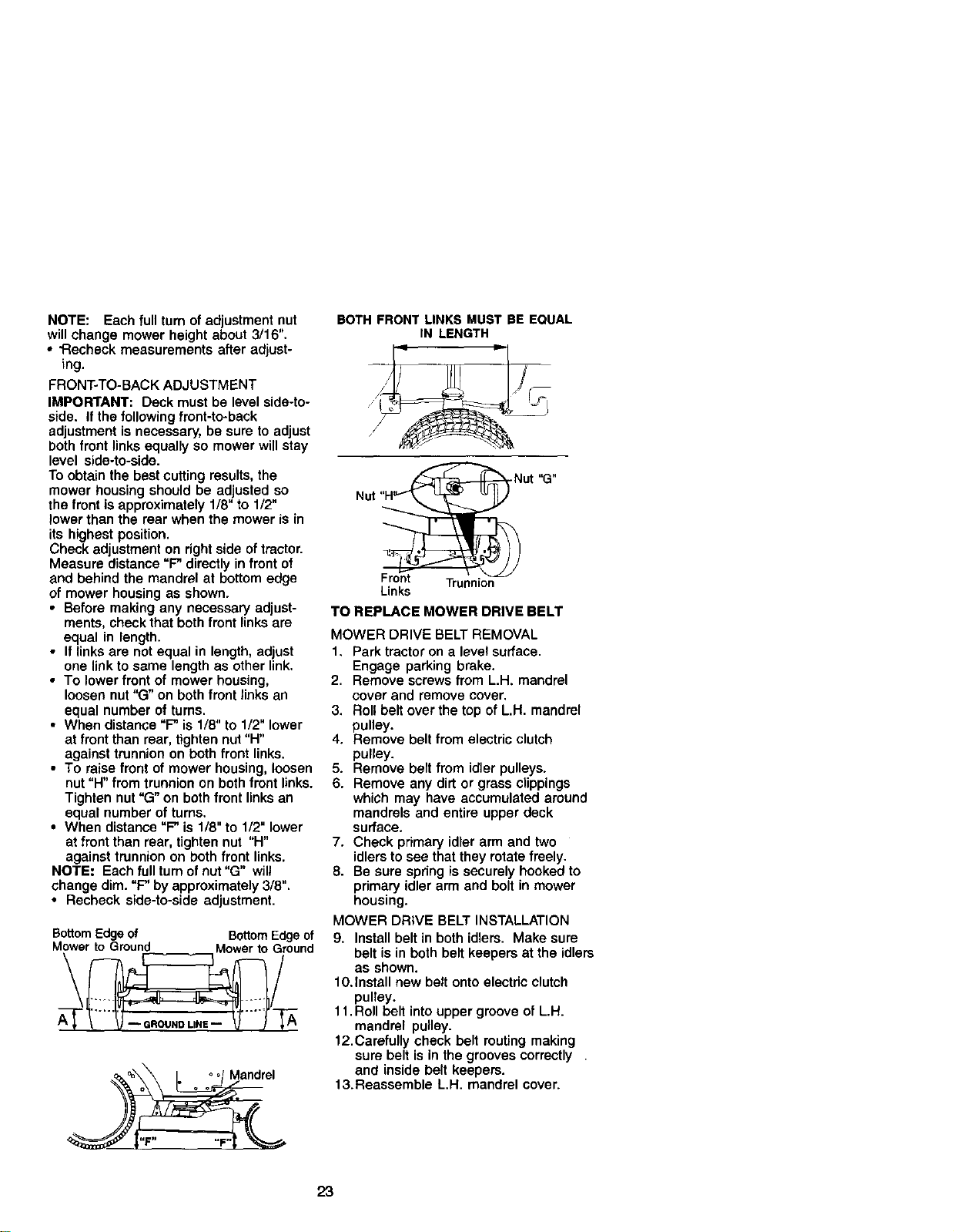
NOTE: Each full turn of adjustment nut
will change mower height about 3/16".
• "Recheck measurements after adjust-
ing.
FRONT-TO-BACK ADJUSTMENT
IMPORTANT: Deck must be level side-to-
side. If the following front-to-back
adjustment is necessary, be sure to adjust
both front links equally so mower will stay
level side-to-side.
To obtain the best cutting results, the
mower housing should be adjusted so
the front is approximately 1/8" to 1/2"
lower than the roar when the mower is in
its highest position.
Check adjustment on right side of tractor.
Measure distance "P directly in front of
and behind the mandrel at bottom edge
of mower housing as shown.
• Before making any necessary adjust-
ments, check that both front links are
equal in length.
• If links are not equal in length, adjust
one link to same length as other link.
• To lower front of mower housing,
loosen nut "G" on both front links an
equal number of turns.
• When distance "P is 1/8" to 1/2" lower
at front than rear, tighten nut "H"
against trunnion on both front links.
• To raise front of mower housing, loosen
nut =H" from trunnion on both front links.
Tighten nut "G" on both front links an
equal number of turns.
• When distance "P is 1/8" to 1/2" lower
at front than rear, tighten nut "H"
against trunnion on both front links.
NOTE; Each full turn of nut "G" will
change dim. "P by approximately 3/8".
• Recheck side-to-side adjustment.
BottomEdgeof BottomEdgeof
M_r to GroundA_" __"" -'_Mower toiround
BOTH FRONT LINKS MUST BE EQUAL
IN LENGTH
Front Trunnion
Links
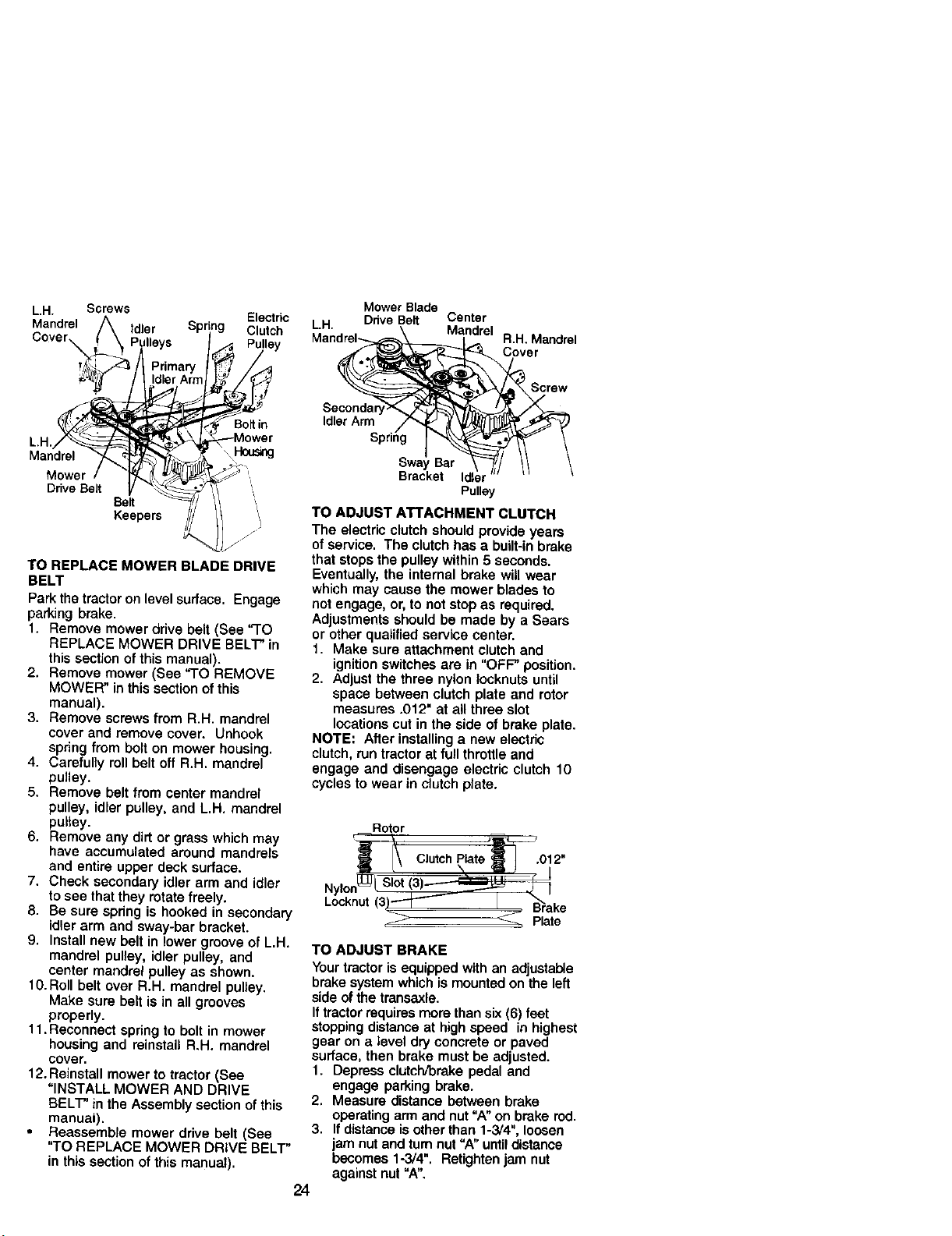
TO REPLACE MOWER DRIVE BELT
MOWER DRIVE BELT REMOVAL
1. Park tractor on a level surface.
Engage parking brake.
2. Remove screws from L.H. mandrel
cover and remove cover.
3. Roll belt over the top of L.H. mandrel
pulley.
4. Remove belt from electric clutch
pulley.
5. Remove belt from idler pulleys.
6. Remove any dirt or grass clippings
which may have accumulated around
mandrels and entire upper deck
surface.
7. Check primary idler arm and two
idlers to see that they rotate freely.
8. Be sure spring is securely hooked to
primary idler arm and bolt in mower
housing.
MOWER DRIVE BELT INSTALLATION
9. Install belt in both idlers. Make sure
belt is in both belt keepers at the idlers
as shown.
10.install new belt onto electric clutch
pulley.
11. Roll belt into upper groove of L.H.
mandrel pulley.
12.Carefully check belt routing making
sure belt is in the grooves correctly
and inside belt keepers.
13.Reassemble L.H. mandrel cover.
23
L.H. Screws
Electric
Mandrel Idler Clutch
Mandrel
Mower
Ddve Belt
Be_
Keepe_
Bo_in
TO REPLACE MOWER BLADE DRIVE
BELT
Park the tractor on level surface. Engage
parking brake.
1. Remove mower drive belt (See "TO
REPLACE MOWER DRIVE BELT" in
this section of this manual).
2. Remove mower (See "TO REMOVE
MOWER" in this section ofthis
manual).
3. Remove screws from R.H. mandrel
cover and remove cover. Unhook
spring from bolt on mower housing.
4. Carefully roll belt off R.H. mandrel
pulley.
5. Remove belt from center mandrel
pulley, idler pulley, and L.H. mandrel
pulley.
6. Remove any dirt or grass which may
have accumulated around mandrels
and entire upper deck surface.
7. Check secondary idler arm and idler
to see that they rotate freely.
8. Be sure spring is hooked in secondary
idler arm and sway-bar bracket.
9. Install new belt in lower groove of L.H.
mandrel pulley, idler pulley, and
center mandrel pulley as shown.
10. Roll belt over R.H. mandrel pulley.
Make sure belt is in all grooves
properly.
11. Reconnect spring to bolt in mower
housing and reinstall R.H. mandrel
cover.
12. Reinstall mower to tractor (See
"INSTALL MOWER AND DRIVE
BELT" in the Assembly section of this
manual).
Reassemble mower drive belt (See
"TO REPLACE MOWER DRIVE BELT"
in this section of this manual).
Mower Blade
L.H. DdveBelt Center
Mandrel_,.,_ Malndrel R.H. Mandrel
J_ _ .-',._,I_'_- Cover
IdlerArm _ _ _ [_L<_/_ _,/
Spring I_._ _ /
swayBar ' q_/ I\ \
Bracket Idl "'"'
Pulle_
TO ADJUST ATTACHMENT CLUTCH
The electric clutch should provide years
of service. The clutch has a built-inbrake
that stops the pulley within 5 seconds.
Eventually, the internal brake will wear
which may cause the mower blades to
not engage, or, to not stop as required.
Adjustments should be made by a Sears
or other qualified eerv_ce center.
1. Make sure attachment ¢lutch and
ignition switches are in "OFF" position.
2. Adjust the three nylon Iocknuts until
space between clutch plate and rotor
measures .012" at all three slot
locations cut in the side of brake plate.
NOTE= After installing a new electric
clutch, run tractor at full throttle and
engage and disengage electric clutch 10
cycles to wear in clutch plate.
Rotor
i
Locknut(3)'_ I _ake
_ Plate
TO ADJUST BRAKE
Your tractor is equipped with an adjustable
brake system which is mounted on the left
side of the trensaxle.
If tractor requires more than six (6) feet
stopping distance at high speed in highest
gear on a _eve| dry concrete or paved
surface, then brake must be adjusted.
1. Depress clutch/brake pedal and
engage parking brake.
2. Measure distance between brake
operating arm and nut "A" on brake rod.
3. If distance is other than 1-3/4", loosen
jam nut and turn nut "A" until distance
becomes 1-3/4". Retighten jam nut
against nut "A".
24
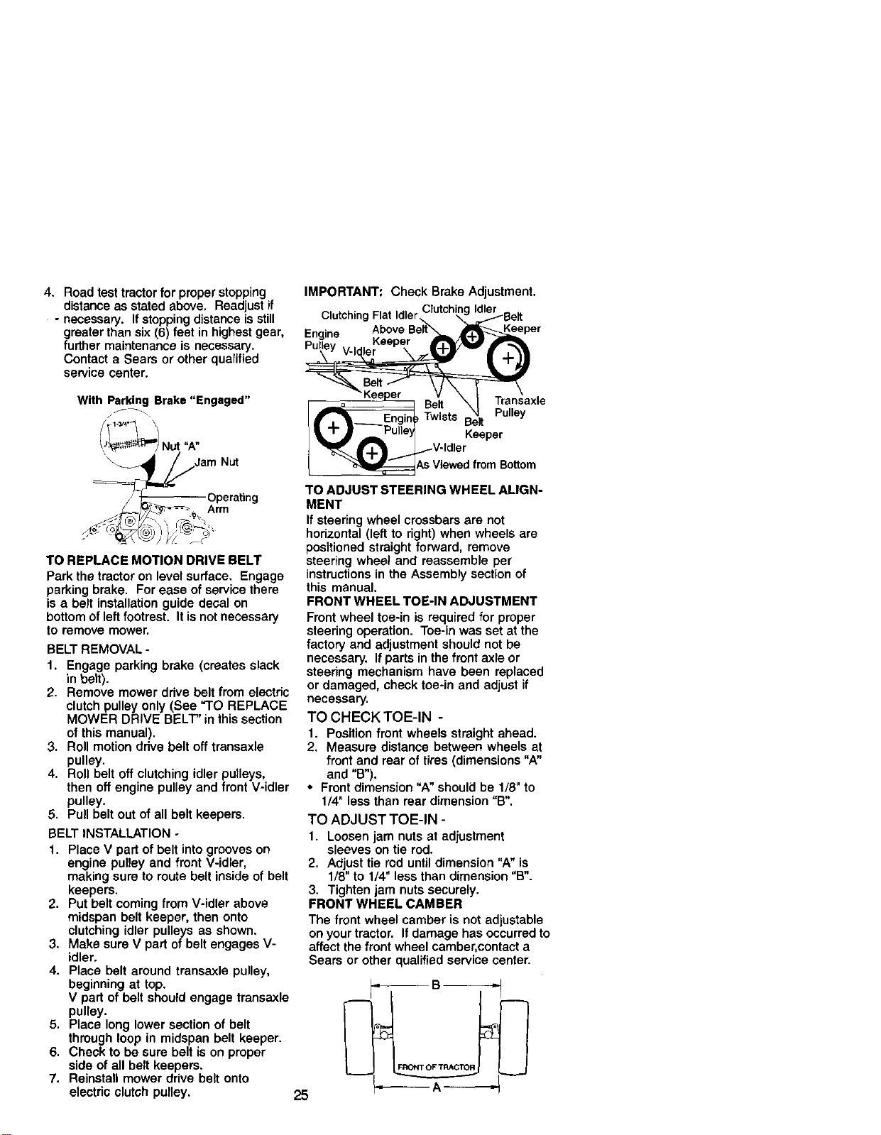
4. Road test tractor for proper stopping
distance as stated above. Readjust if
- necessary. If stopping distance isstill
greater than six (6) feet in highest gear,
further maintenance is necessary.
Contact a Sears or other qualified
service center.
With Parking Brake "Engaged"
Nut "A"
Jam Nut
/J _'_7--_----- Operating
_/_._ -,-_,. Arm
TO REPLACE MOTION DRIVE BELT
Park the tractor on level surface. Engage
parking brake. For ease of service there
is a belt installation guide decal on
bottom of left footrest. It is not necessary
to remove mower.
BELT REMOVAL -
f. Engage parking brake (creates slack
in belt).
2. Remove mower ddve belt from electric
clutch pulley only (See "TO REPLACE
MOWER DRIVE BELT" in this section
of this manual).
3. Roll motion ddve belt off transaxle
pulley.
4. Roll belt off clutching idler pulleys,
then off engine pulley and front V-idler
pulley.
5. Pull belt out of all belt keepers.
BELT INSTALLATION -
1. Place V part of belt into grooves on
engine pulley and front V-idler,
making sure to route belt inside of belt
keepers.
2. Put belt coming from V-idler above
midspan belt keeper, then onto
clutching idler pulleys as shown.
3. Make sure V part of belt engages V-
idler,
4. Place belt around transaxle pulley,
beginning at top.
V part of belt should engage transaxle
pulley.
5. Place long lower section of belt
through loop in midspan belt keeper.
6. Check to be sure belt is on proper
side of all belt keepers.
7. Reinstall mower drive belt onto
electdc clutch pulley.
IMPORTANT: Check Brake Adjustment.
Clutching Flat Idler,
Engine
Keeper Transaxle
-- _ Belt
f _'1 Engin_Twists Belt Pulley
_, "_ J Pulle_ Keeper
_:_As V ewed from Bottom
TO ADJUST STEERING WHEEL ALIGN-
MENT
If steering wheel crossbars are not
horizontal (left to right) when wheels are
positioned straight forward, remove
steering wheel and reassemble per
instructions in the Assembly section of
this manual.
FRONT WHEEL TOE-IN ADJUSTMENT
Front wheel toe-in is required for proper
steering operation. Toe-in was set at the
factory and adjustment should not be
necessary. If parts in the front axle or
steering mechanism have been replaced
or damaged, check toe-in and adjust if
necessary.
TO CHECK TOE-IN -
1. Position front wheels straight ahead.
2. Measure distance between wheels at
front and roar of tires (dimensions "A"
and "B").
• Front dimension "A" should be 1/8" to
1/4" less than rear dimension "B".
TO ADJUST TOE-IN -
1. Loosen jam nuts at adjustment
sleeves on tie rod.
2. Adjust tie rod until dimension "A" is
1/8" to 1/4" less than dimension "B".
3. Tighten jam nuts securely.
FRONT WHEEL CAMBER
The front wheel camber is not adjustable
on your tractor. If damage has occurred to
affect the front wheel camber, contact a
Sears or other qualified service center.
25
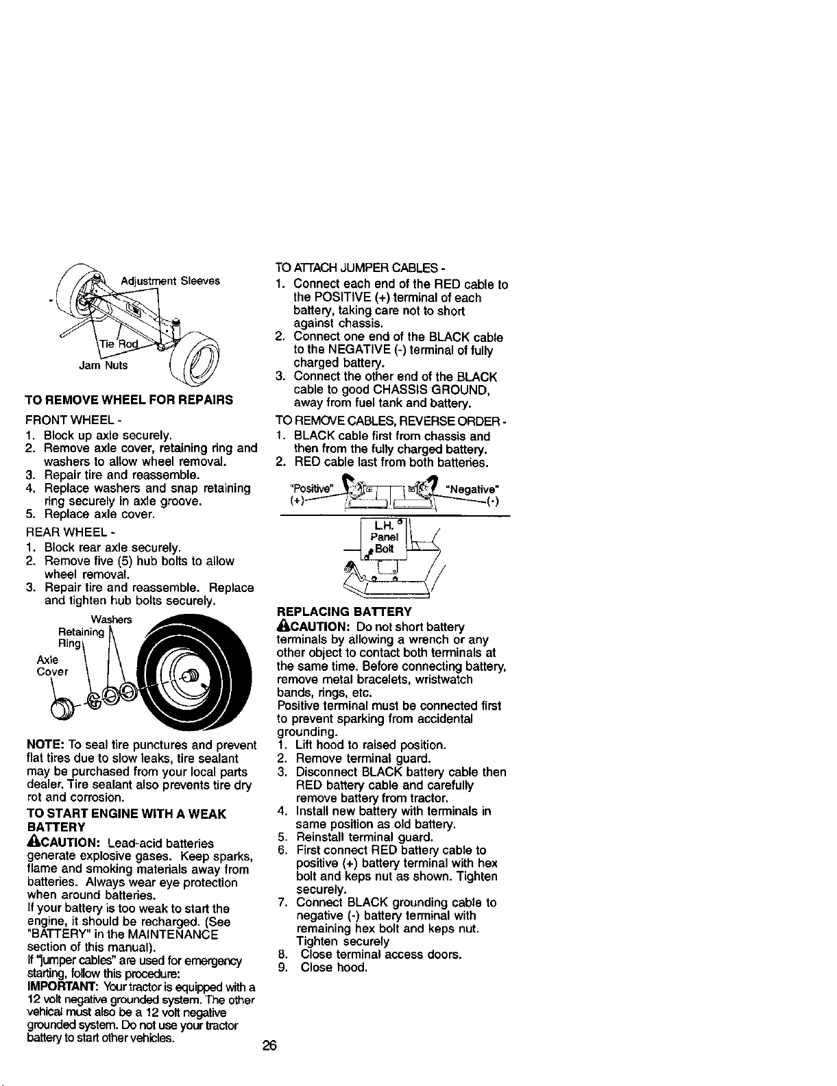
Adjustment Sleeves
Jam Nuts
TO REMOVE WHEEL FOR REPAIRS
FRONT WHEEL -
1. Block up axle securely.
2. Remove axle cover, retaining ring and
washers to allow wheel removal.
3. Repair tire and reassemble.
4. Replace washers and snap retaining
ring securely in axle groove.
5. Replace axle cover.
REAR WHEEL -
1. Block rear axle securely.
2. Remove five (5) hub bolts to allow
wheel removal.
3. Repair tire and reassemble. Replace
and tighten hub botts securely.
Washers
Retainin,
Axle
Cover
NOTE: To seal tire punctures and prevent
flat tires due to slow leaks, tire sealant
may be purchased from your local parts
dealer. Tire sealant also prevents tire dry
rot and corrosion.
TO START ENGINE WITH A WEAK
BATTERY
_I_CAUTION: Lead-acid batteries
generate explosive gases. Keep sparks,
flame and smoking materials away from
batteries. Always wear eye protection
when around batteries.
If your battery is too weak to start the
engine, it should be recharged. (See
"BATTERY" in the MAINTENANCE
section of this manual).
If"jumper cables"are used for emergency
starting,follow this procedure:
IMPORTANT: Yourtractorisequippedwitha
12 volt negativegroundedsystem.The other
vehical must alsobe a 12 voltnegative
groundedsystem.Do not use yourtractor
batteryto startothervehicles.
TO ATTACHJUMPER CABLES -
1. Connect each end of the RED cable to
the POSITIVE (+) terminal of each
battery, taking care not to short
against chassis.
2. Connect one end of the BLACK cable
to the NEGATIVE (-) terminal of fully
charged battery.
3. Connect the other end of the BLACK
cable to good CHASSIS GROUND,
away from fuel tank and battery.
TO REMOVE CABLES, REVERSE ORDER -
1. BLACK cable first from chassis and
then from the fully charged battery.
2. RED cable last from both batteries.
(,)---"'-
REPLACING BATTERY
_CAUTION: Do not short battery
terminals by allowing a wrench or any
other object to contact both terminals at
the same time. Before connecting battery,
remove metal bracelets, wristwatch
bands, rings, etc.
Positive terminal must be connected first
to prevent sparking from accidental
grounding.
t. Lift hood to raised position.
2. Remove terminal guard.
3. Disconnect BLACK battery cable then
RED battery cable and carefully
remove batteP/from tractor.
4. Install new battery with terminals in
same position as old battery.
5. Reinstall terminal guard.
6. First connect RED battery cable to
positive (+) battery terminal with hex
bolt and keps nut as shown. Tighten
securely.
7. Connect BLACK grounding cable to
negative (-) battery terminal with
remaining hax bolt and keps nut.
Tighten securely
8. Close terminal access doors.
9. Close hood.
26
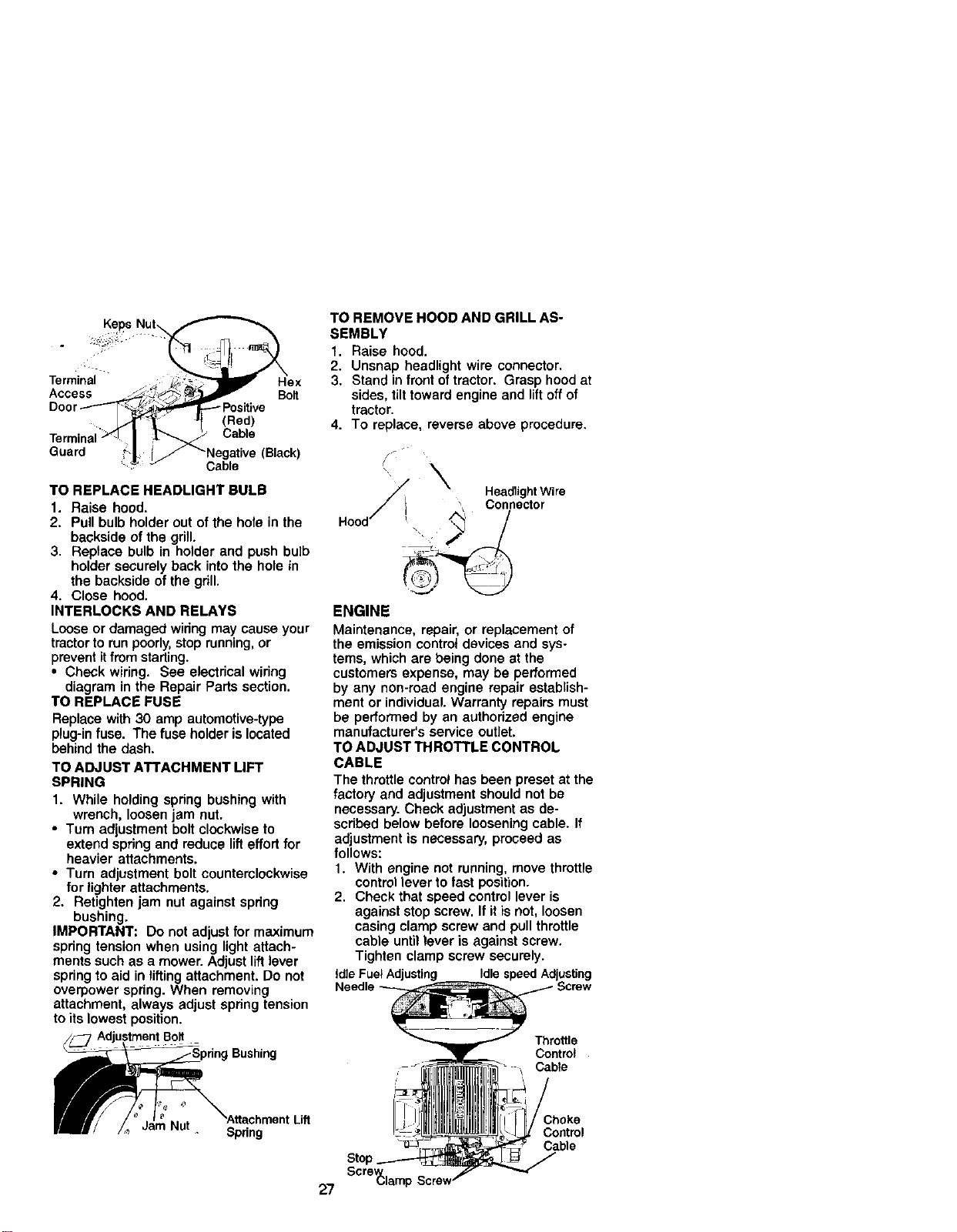
KiP°NU!
Terminal _ ;__-_1_ I_ He×
Door----_.'_ _*_----_ Positive
. - <Rod>
Terminal_ | _ Cable
Guard _-| l_Negative (Black)
':'__ J" Cable
TO REPLACE HEADLIGHT BULB
1. Raise hood.
2. Pull bulb holder out of the hole in the
backside of the grill.
3, Reptace bulb in holder and push bulb
holder securely back into the hole in
the backside of the grill.
4. Close hood.
INTERLOCKS AND RELAYS
Loose or damaged widng may cause your
tractor to run poorly, atop running, or
prevent itfrom starting.
• Check wiring. See electrical wiring
diagram in the Repair Parts section.
TO REPLACE FUSE
Replace with 30 amp automotive-type
plug-in fuse. The fuse holder is located
behind the dash.
TO ADJUST ATTACHMENT LIFT
SPRING
1. While holding spdng bushing with
wrench, loosen jam nut.
• Turn adjustment bolt clockwise to
extend spring and reduce lifteffort for
heavier attachments.
• Turn adjustment bolt counterclockwise
for lighter attachments.
2. Retighten jam nut against spdng
bushing.
IMPORTANT: Do not adjust for maximum
spdng tension when using light attach-
ments such as a mower. Adjust lift lever
spring to aid in lifting attachment. Do not
overpower spring. When removing
attachment, always adjust spring tension
to its lowest position.
/_ Adjustment Bolt
ng Bushing
_fi F JatmN.t "AttachmentLift
|ll/ /,_ aam Nu( _ Spring
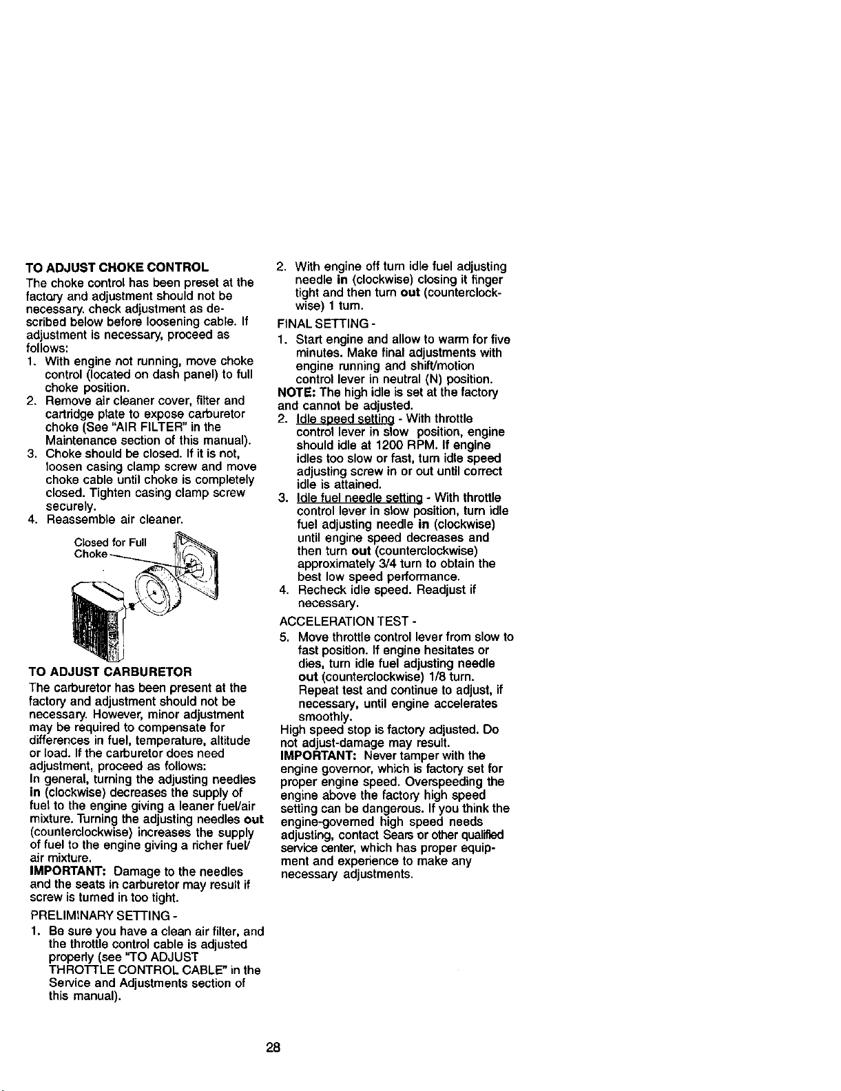
TO REMOVE HOOD AND GRILL AS-
SEMBLY
1. Raise hood.
2, Unsnap headlight wire connector,
3. Stand in front of tractor. Grasp hood at
sides, tilt toward engine and liftoff of
tractor,
4. To replace, reverse above procedure.
HeadlightWire
,
ENGINE
Maintenance, repair, or replacement of
the emission controt devices and sys-
tems, which are being done at the
customers expense, may be performed
by any non-read engine repair ectablish-
ment or individual. Warranty repairs must
be performed by an authorized engine
manufacturer's service outlet.
TO ADJUST THROTTLE CONTROL
CABLE
The throttle control has been preset at the
factory and adjustment should not be
necessary. Check adjustment as de-
scdbed below before loosening cable. If
adlustment is necessary, proceed as
follows:
1. With engine not running, move throttle
control lever to fast position.
2. Check that speed control lever is
against stop screw. If it is not, loosen
casing clamp screw and pull throttle
cable until lever is against screw.
Tighten clamp screw securely.
tdle Fuel Adjusting Idlespeed Adjusting
Throttle
Control
Cable
Choke
Control
Cable
27 Scre_lamp
TO ADJUST CHOKE CONTROL
The choke control has been preset at the
fact_'y and adjustment should not be
necessary, check adjustment as de-
scribed below before loosening cable. If
adjustment is necessary, proceed as
follows:
1. With engine not running, move choke
control (located on dash panel) to full
choke position.
2. Remove air cleaner cover, filter and
cartridge plate to expose carburetor
choke (See "AIR FILTER" in the
Maintenance section of this manual).
3. Choke should be closed. If it is not,
loosen casing clamp screw and move
choke cable until choke is completely
closed. Tighten casing clamp screw
securely.
4. Reassemble air cleaner.
Closed for Full
TO ADJUST CARBURETOR
The carburetor has been present at the
factory and adjustment should not be
necessary. However, minor adjustment
may be required to compensate for
differences in fuel, temperature, altitude
or load. If the carburetor does need
adjustment, proceed as follows:
In general, turning the adjusting needles
in (clockwise) decreases the supply of
fuel to the engine giving a leaner fuel/air
mixture. Turning the adjusting needles out
(counterclockwise) increases the supply
of fuel to the engine giving a richer fuel/
air mixture.
IMPORTANT: Damage to the needles
and the seats in carburetor may result if
screw is turned in too tight.
PRELIMINARY SETTING -
1. Be sure you have a clean air filter, and
the throttle control cable is adjusted
properly (see "TO ADJUST
THROTTLE CONTROL CABLE" in the
Service and Adjustments section of
this manual).
2. With engine off turn idle fuel adjusting
needle in (clockwise) closing it finger
tight and then turn out (counterclock-
wise) 1 tum.
FINAL SETTING -
1. Start engine and allow to warm for five
minutes. Make final adjustments with
engine running and shift/motion
control lever in neutral (N) position.
NOTE: The high idle is set at the factory
and cannot be adjusted.
2. Idle speed settina - With throttle
control lever in slow position, engine
should idle at 1200 RPM. If engine
idles too slow or fast, turn idle speed
adjusting screw in or out until correct
idle is attained.
3. Idle fuel needle settina - With throttle
control lever in slow position, turn idle
fuel adjusting needle in (clockwise)
until engine speed decreases and
then turn out (counterclockwise)
approximately 3/4 turn to obtain the
best low speed performance.
4. Recheck idle speed. Readjust if
necessary.
ACCELERATION TEST °
5. Move throttle control lever from slow to
fast position. If engine hesitates or
dies, turn idle fuel adjusting needle
eut (counterclockwise) 1/8 turn.
Repeat test and continue to adjust, if
necessary, until engine accelerates
smoothly.
High speed stop is factory adjusted. Do
not adjust-damage may result.
IMPORTANT: Never tamper with the
engine governor, which is factory set for
proper engine speed. Overepeeding the
engine above the factory high speed
setting can be dangerous. If you think the
engine-governed high speed needs
adjusting, contact Sears or other qualified
service center, which has proper equip-
ment and experience to make any
necessary adjustments.
28
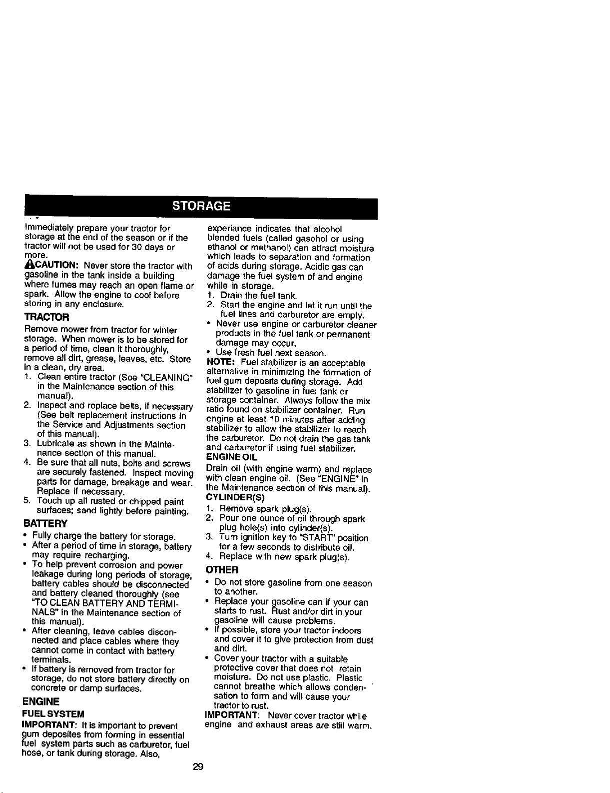
Immediately prepare your tractor for
storage at the end of the season or if the
tractor will not be used for 30 days or
more.
_I,CAUTION: Never store the tractor with
gasoline in the tank inside a building
where fumes may reach an open flame or
spark. Allow the engine to cool before
storing in any enclosure.
TRACTOR
Remove mower from tractor for winter
storage. When mower is to be stored for
a period of time, clean it thoroughly,
remove all dirt, grease, leaves, etc. Store
in a clean, dry area.
1. Clean entire tractor (See "CLEANING"
in the Maintenance section of this
manual).
2. Inspect and replace be_ts, if necessary
(See belt replacement instructions in
the Service and Adjustments section
of this manual).
3. Lubricate as shown in the Mainte-
nance section of this manual.
4. Be sure that all nuts, bolts and screws
are securely fastened. Inspect moving
parts for damage, breakage and wear.
Replace if necessary.
5. Touch up all rusted or chipped paint
surfaces; sand lightly before painting.
BA'I'rERY
• Fully charge the battery for storage.
• After a period of time in storage, battery
may require recharging.
• To help prevent corrosion and power
leakage during long periods of storage,
battery cables should be disconnected
and battery cleaned thoroughly (see
'q'O CLEAN BATTERY AND TERMI-
NALS" in the Maintenance section of
this manual).
• After cleaning, leave cables discon-
nected and place cables where they
cannot come in contact with battery
terminals.
• If battery is removed from tractor for
storage, do not store battery directly on
concrete or damp surfaces.
ENGINE
FUEL SYSTEM
IMPORTANT: It isimportant to prevent
gum deposites from forming in essential
fuel system parts such as carburetor, fuel
hose, or tank during storage. Also,
experiance indicates that alcohol
blended fuels (called gasohol or using
ethanol or methanol) can attract moisture
which leads to separation and formation
of acids during storage. Acidic gas can
damage the fuel system of and engine
while in storage.
1. Drain the fuel tank.
2. Start the engine and let it run unti_the
fuel lines and carburetor are empty.
• Never use engine or carburetor cleaner
products in the fuel tank or permanent
damage may occur.
• Use fresh fuel next season.
NOTE: Fuel stabilizer is an acceptable
a_ternat{ve {n minimizing the formation of
fuel gum deposits during storage. Add
stabilizer to gasoline in fuel tank or
storage container. Always follow the mix
ratio found on stabilizer container. Run
engine at least 10 minutes after adding
stabilizer to allow the stabilizer to reach
the carburetor. Do not drain the gas tank
and carburetor if using fuel stabilizer.
ENGINEOIL
Drain oil (with engine warm) and replace
with clean engine oil. (See "ENGINE" in
the Maintenance section of this manual).
CYLINDER(S)
t. Remove spark plug(s).
2. Pour one ounce of oil through spark
plug hole(s) into cylinder(s).
3. Turn ignition key to "START" position
for a few seconds to distribute oil.
4. Replace with new spark plug(s).
OTHER
• Do not store gasoline from one season
to another,
• Replace your gasoline can if your can
starts to rest. Rust and/or dirt in your
gasoline will cause problems.
• If possible, store your tractor indoors
and cover it to give protection from dust
and dirt.
• Cover your tractor with a suitable
protective cover that does not retain
moisture, Do not use plastic. Plastic
cannot breathe which allows conden-
sation to form and will cause your
tractor to rust.
IMPORTANT: Never cover tractor while
engine and exhaust areas are still warm.
29
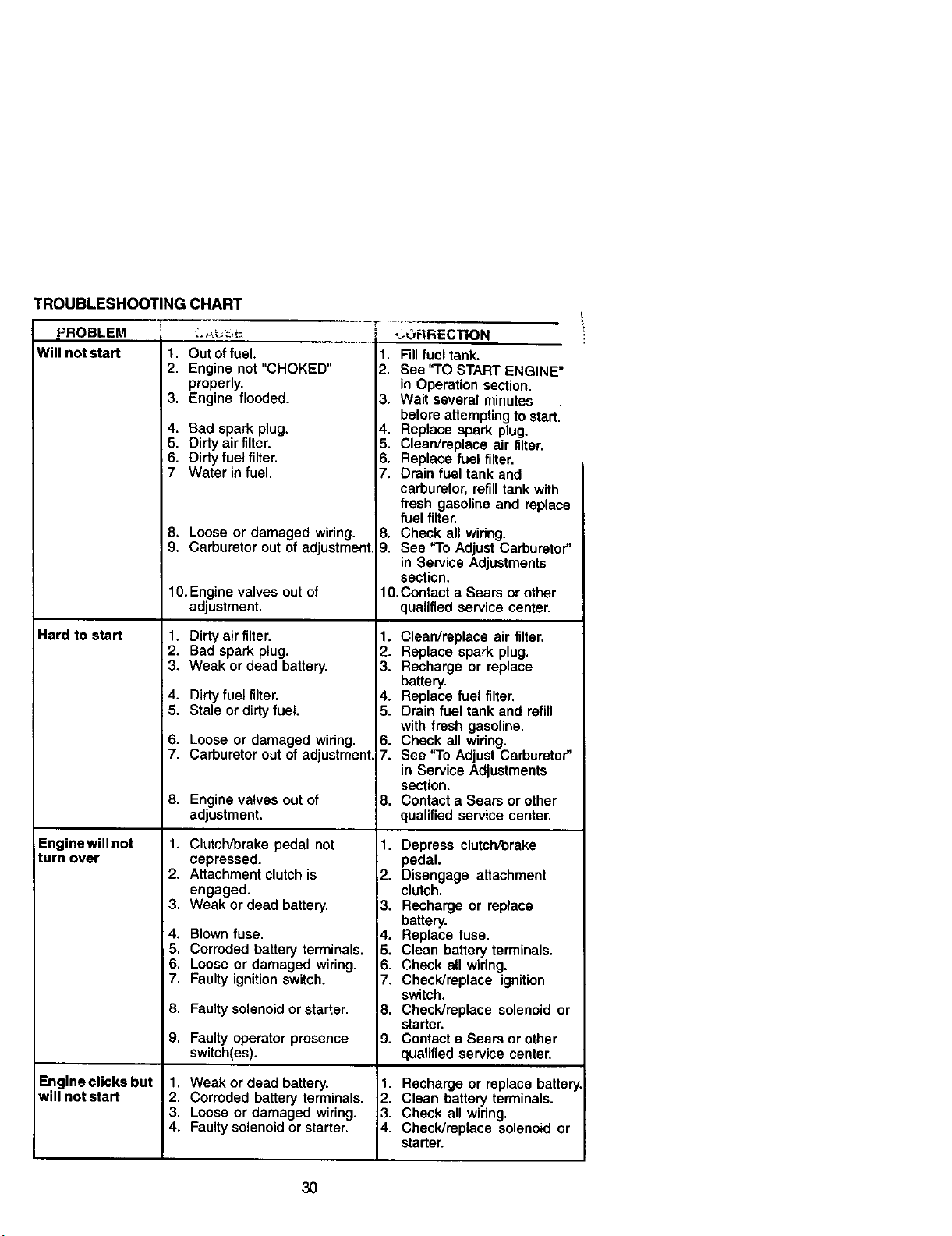
TROUBLESHOOTINGCHART
_ROBLEM
Will not start 1.
2.
3.
4.
5.
_6.
i7
Hard to start
Enginewill not
turn over
Engine clicks but
will not start
',-,_; _-,-_:_ _RRECTION
Out of fuel.
Engine not "CHOKED"
properly.
Engine flooded.
Bad spark plug.
Dirty air filter.
Dirty fuel filter.
Water in fuel.
8. Looseor damaged wiring.
9. Carburetorout ofadjustment,
10.Engine valves outof
adjustment.
1. Dirty air filter.
2. Bad spark plug.
3. Weak or dead battery.
4. Dirty fuel filter.
5. Stale or dirty fuel.
6. Loose or damaged wiring.
7. Carburetor out of adjustment,
8. Engine valves out of
adjustment.
1. Clutch/brake pedal not
depressed.
2. Attachment clutch is
engaged.
3. Weak or dead battery.
4. Blown fuse.
5. Corroded battery terminals.
6. Loose or damaged wiring.
7. Faulty ignition switch.
8. Faulty solenoid or starter.
9. Faultyoperatorpresence
switch(es).
1. Fill fuel tank.
2. See "TO START ENGINE"
in Operation section.
3. Wait several minutes
before attempting to start.
4. Replace spark plug.
5. Clean/replace air filter.
6. Replace fuel filter.
7. Drain fuel tank and
carburetor, refill tank with
fresh gasoline and replace
fuel filter.
8. Check all wiring.
9. See "To Adjust Carburetor"
in Service Adjustments
section.
1O.Contact a Sears or other
qualified service center.
1. Clean/replace air filter.
2. Replace spark plug.
3. Recharge or replace
battery.
4. Replace fuel filter.
5. Drain fuel tank and refill
with fresh gasoline.
6. Check all widng.
7. See 'q'o Adjust Carburetor"
in Service Adjustments
section.
8. Contact a Sears or other
qualified service center.
1. Depress clutch/brake
pedal.
,2. Disengage attachment
clutch.
13. Recharge or replace
battery.
4. Replace fuse.
5. Clean battery terminals.
6. Check all widng.
7. Check]replace ignition
switch.
8. Check/replace solenoid or
starter.
9. Contact a Sears or other
qualified service center.
1. Weak or dead battery.
2. Corroded battery terminals.
3. Loose or damaged wiring.
4. Faulty solenoid or starter.
1. Recharge or replace battery
2. Clean battery terminals.
3, Check all wiring.
4, Check/replace solenoid or
starter.
3O
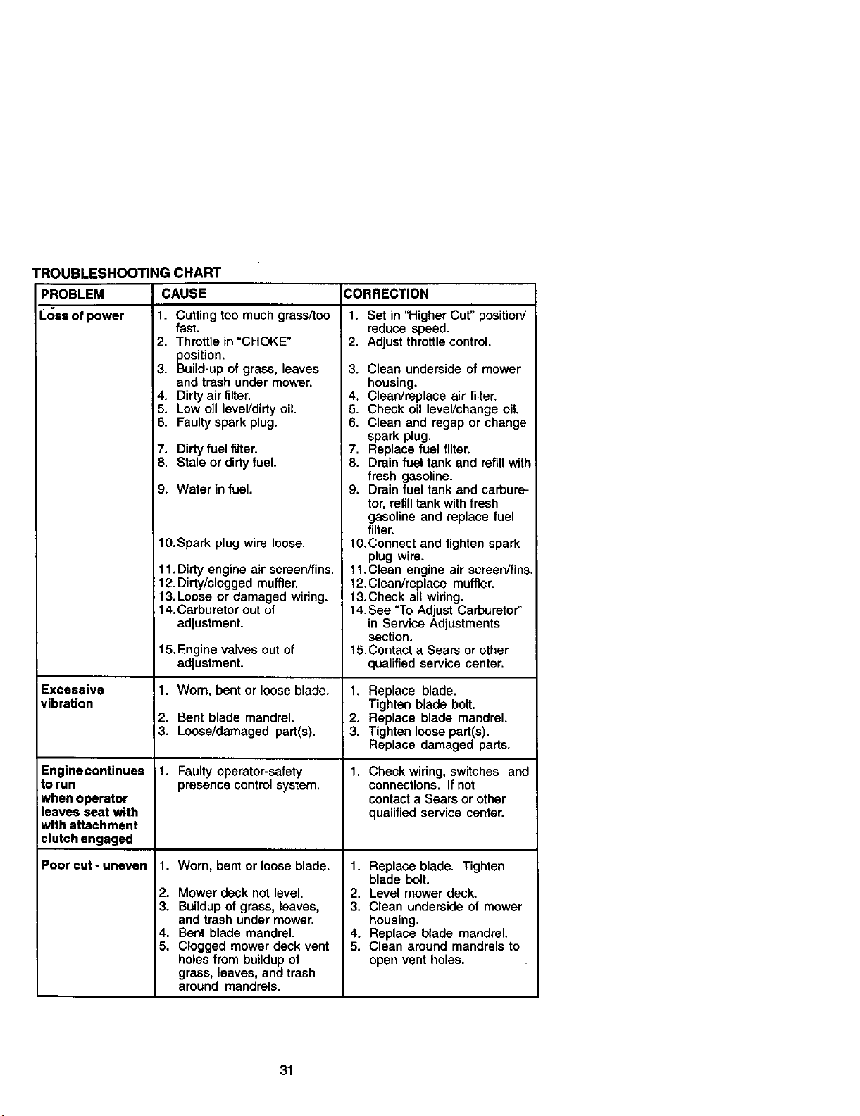
TROUBLESHOOTING CHART
PROBLEM CAUSE
Loss of power 1. Cutting too much grass/too
fast.
2. Throtfie in "CHOKE"
position.
3. Build-up of grass, leaves 3.
and trash under mower,
4. Dirty air filter. 4.
5. Low oil level/dirty oil. 5.
6. Faulty spark plug, 6.
7. Dirty fuel filter. 7.
8. Stale or dirty fuel. 8.
9. Water in fuel.
lO.Spark plug wire loose.
Excessive
vibration
Enginecontinues
to run
when operator
leaves seat with
with attachment
clutch engaged
Poor cut- uneven
11. Dirty engine air screen/fins.
12. Dirty/clogged muffler.
;13.Loose or damaged widng.
14.Carburetor out of
adjustment.
15. Engine valves out of
adjustment.
1. Worn, bent or loose blade.
2. Bent blade mandrel.
3. Loose/damaged part(s).
1. Faulty operator-safety
presence control system.
1. Worn, bent or loose blade.
2. Mower deck not level.
3. Buildup of grass, leaves,
and trash under mower.
4. Bent blade mandrel.
5. Clogged mower deck vent
holes from buildup of
grass, leaves, and trash
around mandrels.
CORRECTION
1. Set in "Higher Cut" position/
reduce speed.
2. Adjust throttle control.
Clean underside of mower
housing.
Clean/replace air filter.
Check oil level/change oil.
Clean and regap or change
spark plug.
Replace fuel filter.
Drain fuel tank and refill with
fresh gasoline.
9. Drain fuel tank and carbure-
tor, refill tank with fresh
gasoline and replace fuel
filter.
10.Connect and tighten spark
plug wire.
11.Clean engine air screen/fins,
12. Clean/replace muffler.
13.Check all wiring.
14. See "To Adjust Carburetor"
in Service Adjustments
section.
15.Contact a Sears or other
qualified service center.
1. Replace blade.
Tighten blade bolt.
2. Replace blade mandrel.
3. Tighten loose part(s).
Replace damaged parts.
1. Check wiring, switches and
connections. If not
contact a Sears or other
qualified service center.
1. Replace blade. Tighten
blade bolt.
2. Level mower deck.
3. Clean underside of mower
housing.
4. Replace blade mandrel.
5. Clean amund mandrels to
open vent holes.
31
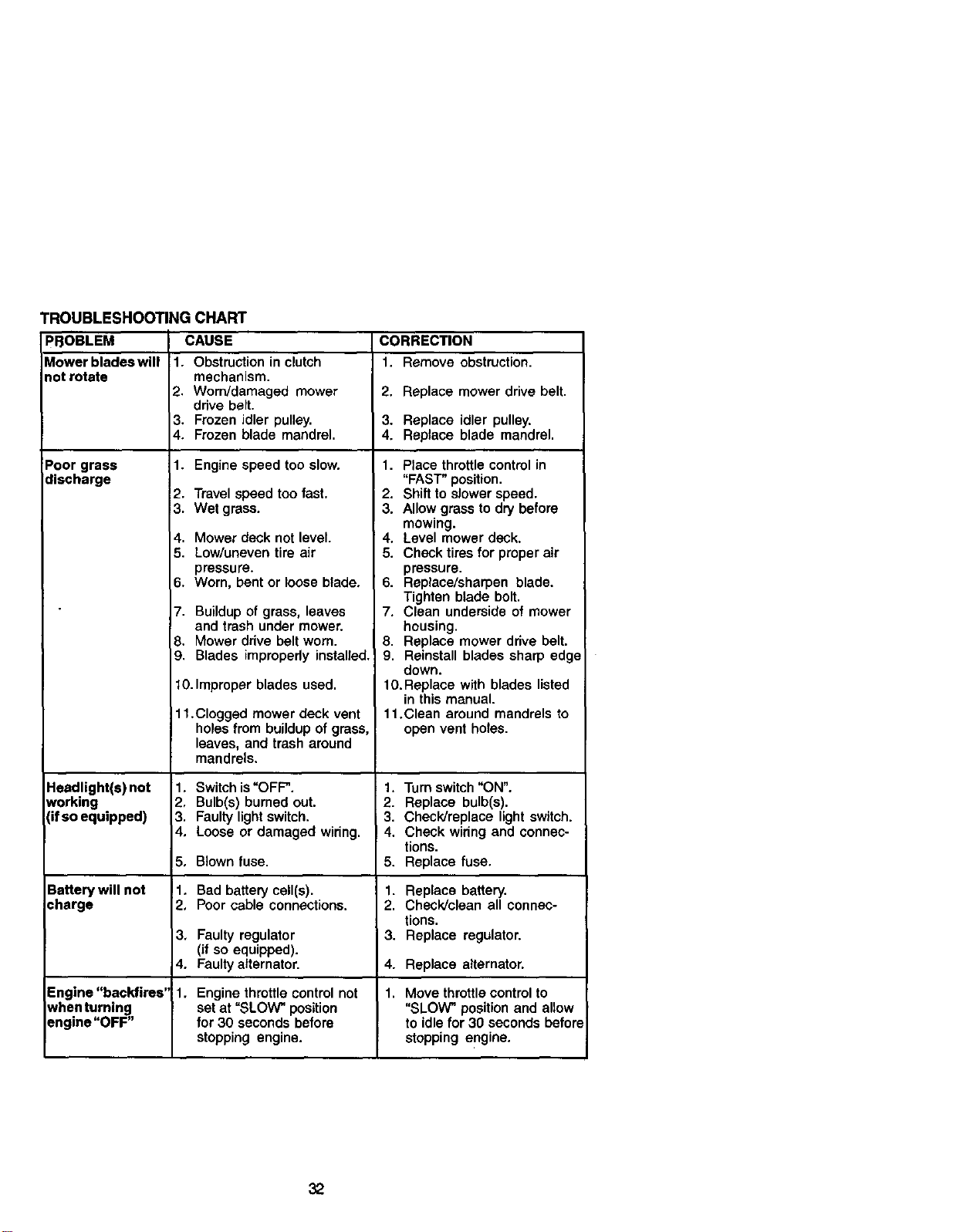
TROUBLESHOOTING CHART
PBOBLEM CAUSE CORRECTION
Mower blades will 1. Obstruction in clutch 1. Remove obstruction,
not rotate mechanism.
2. Worn/damaged mower 2. Replace mower drive belt.
drive belt.
3, Frozen idler pulley. 3. Replace idler pulley.
4. Frozen blade mandrel. 4. Replace blade mandrel.
Poor grass 1. Engine speed too slow.
discharge
Headlight(s)not
working
(if so equipped)
Battery will not
:harge
2. Travel speed too fast.
3. Wet grass.
4. Mower deck not level.
5. Low/uneven tire air
pressure.
6. Worn, bent or toose blade,
7. Buildup of grass, leaves
and trash under mower.
8. Mower ddve belt worn.
9. Blades impropedy installed.
10.Improper blades used.
11.Clogged mower deck vent
holes from buildup of gross,
leaves, and trash around
mandrels.
1, Switch is "OFF".
2, Bulb(s) burned out.
3, Faulty light switch.
4, Loose or damaged widng.
5, Blown fuse.
1. Bad battery cell(s).
2, Poor cable connections.
1. Place throttle control in
"FAST" position.
2. Shift to slower speed.
3. Allow grass to dry before
mowing.
4, Level mower deck.
5. Check tires for proper air
pressure.
6. Replace/sharpen blade.
Tighten blade bolt.
7. Clean underside of mower
housing.
8. Replace mower drive belt.
9. Reinstall blades sharp edge
down.
10. Replace with blades listed
in this manual.
11.Clean around mandrels to
open vent holes.
1. Turn switch "ON".
2. Replace bulb(s).
3. Check/replace light switch.
4. Check widng and connec-
tions.
5. Replace fuse,
1. Replace battery.
2. Check/clean all connec-
tions.
3. Replace regulator.3, Faulty regulator
(if so equipped).
4. Faulty alternator. 4. Replace alternator.
Engine "backfires" 1. Engine throttle control not 1. Move throttle control to
_vhenturning set at "SLOW" position "SLOW" position and allow
sngine"OFF" for 30 seconds before to idle for 30 seconds before
stopping engine, stopping engine.
32
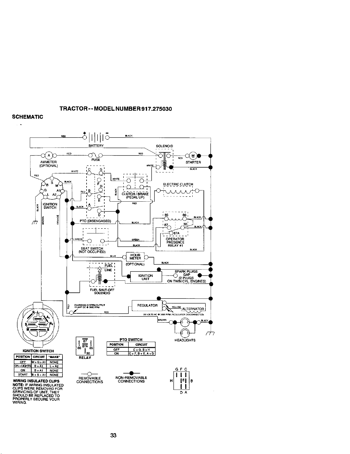
SCHEMATIC
TRACTOR -- MODEL NUMBER 917.275030
AMMETER
_(OPTIONAL)
)BSI
3
_NITIOI,
3WITCH
IGNITION SWITCH
WIRING INSULATED CLIPS
NOTE: IF WIRING INSULATED
CLIPS WERE REMOVED FOR
SERVICING OF UNIT, THEY
SHOULD BE REPLACED TO
PROPERLY SECURE YOUR
WIRING,
BAKERY SOLENOID
r i
-- WWIT_b I STARTER
rC G _ _ _c_
WHI_ II t _• -
i I _rr£ i
_. =,_ u, _ : (2)--j
i_ t _ F t I + ' ELECTRIC CLUTCH
_K I A i ;
/
_e_= t , o_ OPERATOR
L ....... _CK RELAY #1
/ SEAT SWITCH _J RELAY #1 E(_CK
L_ (NOT OCCUPIED)
; FUK 1 _K
: UNE: _" SPARKeLUGS
_ (2 PLUGS
UNIT
I ON TWIN CYL, ENGINES)
L ..... i
FUEL SHUT_)FF
PTO SWITCH HEADLIGHTS
Posn'ION CIRCUIT
ON C+F,B+EIA+D
OFF C+G,B÷H
RELAY
GFC
REMOVABLE NON-REMOVABLE
CONNECTIONS CONNECTIONS H E
DA
33
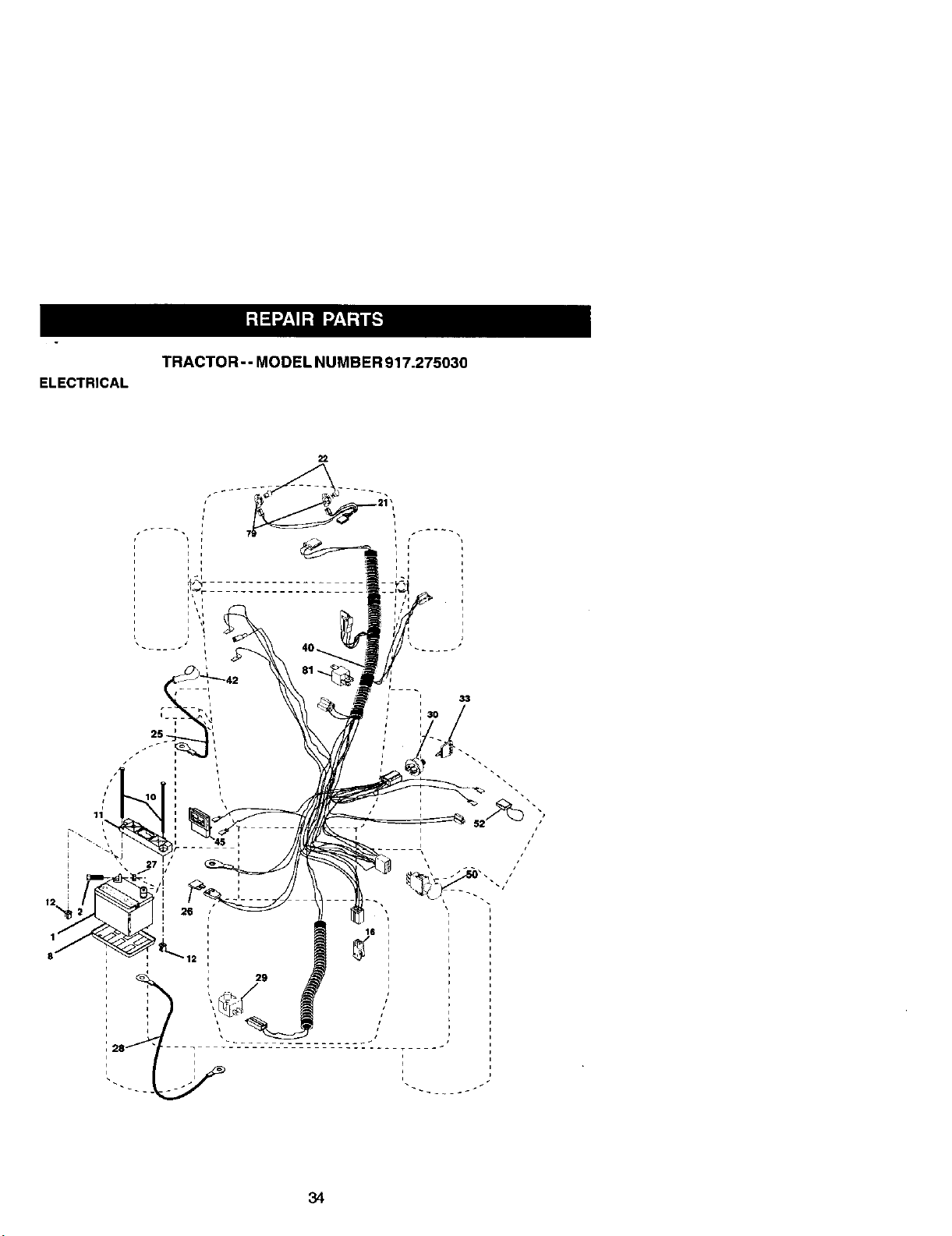
ELECTRICAL
TRACTOR - - MODEL NUMBER 917.275030
22
34
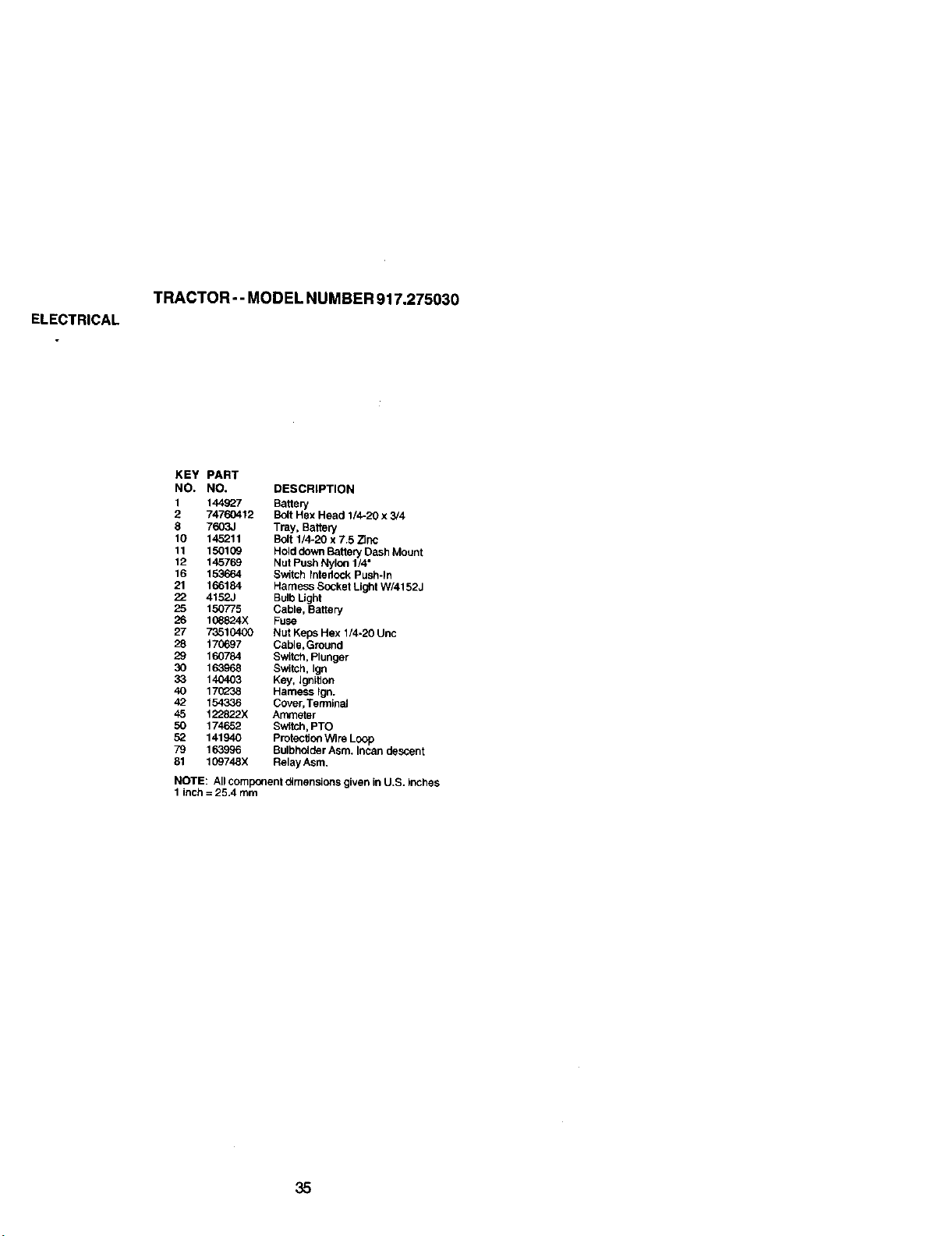
ELECTRICAL
TRACTOR-- MODEL NUMBER 917.275030
KEY PART
NO, NO, DESCRIPTION
1 144927 Battery
2 74760412 Bolt Hex Head 1/4-20 x 3/4
8 7603J Tray, Battery
10 145211 Bolt 1/4-20 x 7.5 Zinc
11 150109 Hold down Battery Dash Mount
12 145769 Nut Push Nylon 1/4"
16 153664 Switch Intedock Push-In
21 166184 Harness Socket Light W/4152J
22 4152J Bulb Ught
25 150775 Cable, Battery
26 108824)( Fuse
27 73510400 Nut Keps Hex 1/4-20 Unc
28 170697 Cable,Ground
29 160784 Switch, Plunger
30 163968 Switch, Ign
33 140403 Key, Ignition
40 170238 Harness Ign.
42 154336 Cover, Terminal
45 122822X Ammeter
50 174652 Switch, PTO
52 141940 Protection Wire Loop
79 163996 Bulbhdider Asm. Incan descent
81 109748X Relay Asm.
NOTE: All component dimensions given in U.S. inches
1 inch = 25.4 mm
35
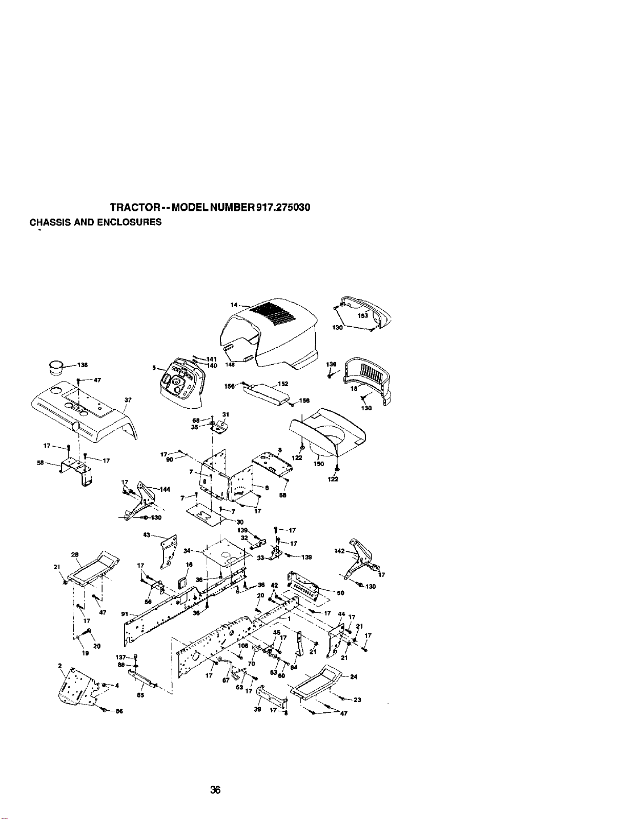
TRACTOR--MODELNUMBER917.275030
CHASSISANDENCLOSURES
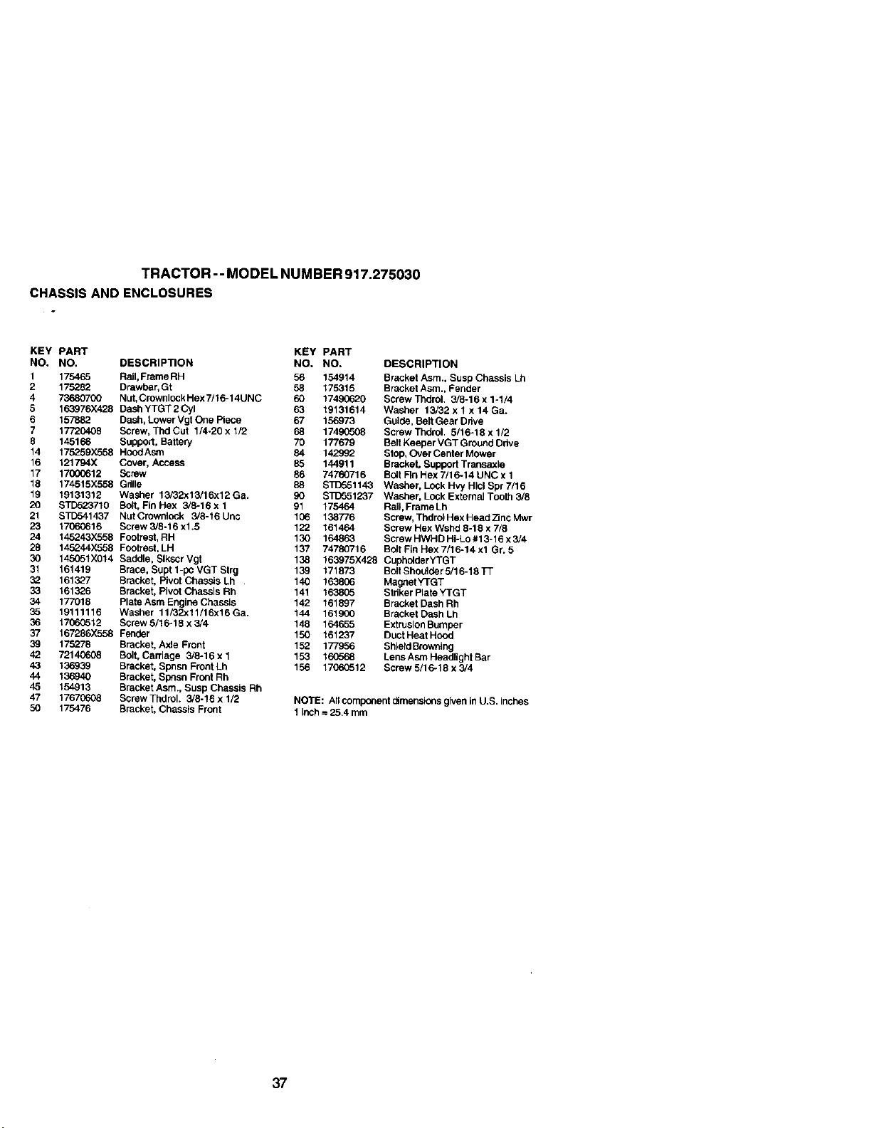
TRACTOR - - MODEL NUM BER 917.275030
CHASSIS AND ENCLOSURES
KEY PART
NO. NO,
1 175465
2 175282
4 73680700
5 1¢o3976X428
6 157882
7 17720408
8 145166
14 175259X568
16 121794X
17 17000612
18 174515X558
19 19131312
20 STD523710
21 STD541437
23 17060616
24 145243X558
28 145244X558
30 1_1X014
31 161419
32 161327
33 161326
34 177018
35 19111116
36 17060512
37 167286X558
39 175278
42 72140608
43 136939
44 136940
45 154913
47 t 767(_8
50 175476
KEY PART
DESCRIPTION NO. NO. DESCRIPTION
RaiI, FrameRH 56 154914 Bracket Asm., Susp Chassis Lh
Drawbar, Gt 58 175315 Bracket Asm,, Fender
Nut, CrownlockHex7/16-14UNC 60 17490620 Screw ThdroL 3/8o16 x 1-1/4
DashYTGT2Cyl 63 t9131614 Washer 13/32 x 1 x 14 Ga.
Dash, Lower Vgt One Piece 67 156973 Guide, Bait Gear Drive
Screw, Thd Cut 1/4-20 x 1/2 68 174£0508 Screw Thdrol. 5/16=18 x 1/2
Support, Battery 70 177679 Bait Keeper VGT Ground Odve
HoodAsm 84 142992 Stop, Over Center Mower
Cover, Access 85 144911 BrackeL Support Transaxle
Screw 86 74760716 Bolt Fin Hex 7/16=14 UNC x 1
Gdlle 88 ST[To51143 Washer, Lock Hvy Hlcl Spr 7/16
Washer 13/32x13/16x12 Ga. 90 S_T_51237 Washer, Lock External Too_ 3/8
Bolt, Fin Hex 3/8-16 x 1 91 175464 Rail, Frame Lh
NutCrownl_.k 3/8-t6Unc 106 138776 Screw, ThdroIHexHead;SncMwr
Screw 3/6=16 x1.5 122 161464 Screw Hex Wshd 8-16 x 7/8
Footrest, RH 130 164863 Screw HWHD Hi-Lo #13-16 x 3/4
Footrest, LH 137 74780716 Bolt Fin Hex 7/16-14 xl Gr. 5
Saddle, Slkscr Vgt 138 t63975X428 CupholderYTGT
Brace, Supt 1-pe VGT Strg 139 171873 Bolt Shoulder 5/16-t 8 _
Bracket, Pivot Chassis Lh 140 163806 MagnetYTGT
Bracket, Pivot Chassis Rh 141 1638_5 Striker Plate YTGT
Plate Asm Engine Chassis 142 161897 Bracket Dash Rh
Washer 11/_32x11/16xt 6 Ga. 144 161900 Bracket Dash Lh
Screw 6/1 6-18 x 3/4 148 164655 Extrusion Bumper
Fender 150 161237 Duct Heat Hood
Bracket, Axle Front 152 177956 Sh_erdBrowning
Solt, Caniage 3/6=16xl 153 160568 LensAsmHeadlightSar
Bracket, Spnsn Front Lh 156 17060512 Screw 5/16-18 x 3/4
Bracket, Spesn Front Rh
Bracket Asm., Susp Chassis Rh
Screw Thdrol. 3/8-16 x 1/2 NOTE: All component dimenslc_s given in U.S, inches
Bracket, Chassis Front 1 Inch --25.4 mm
37
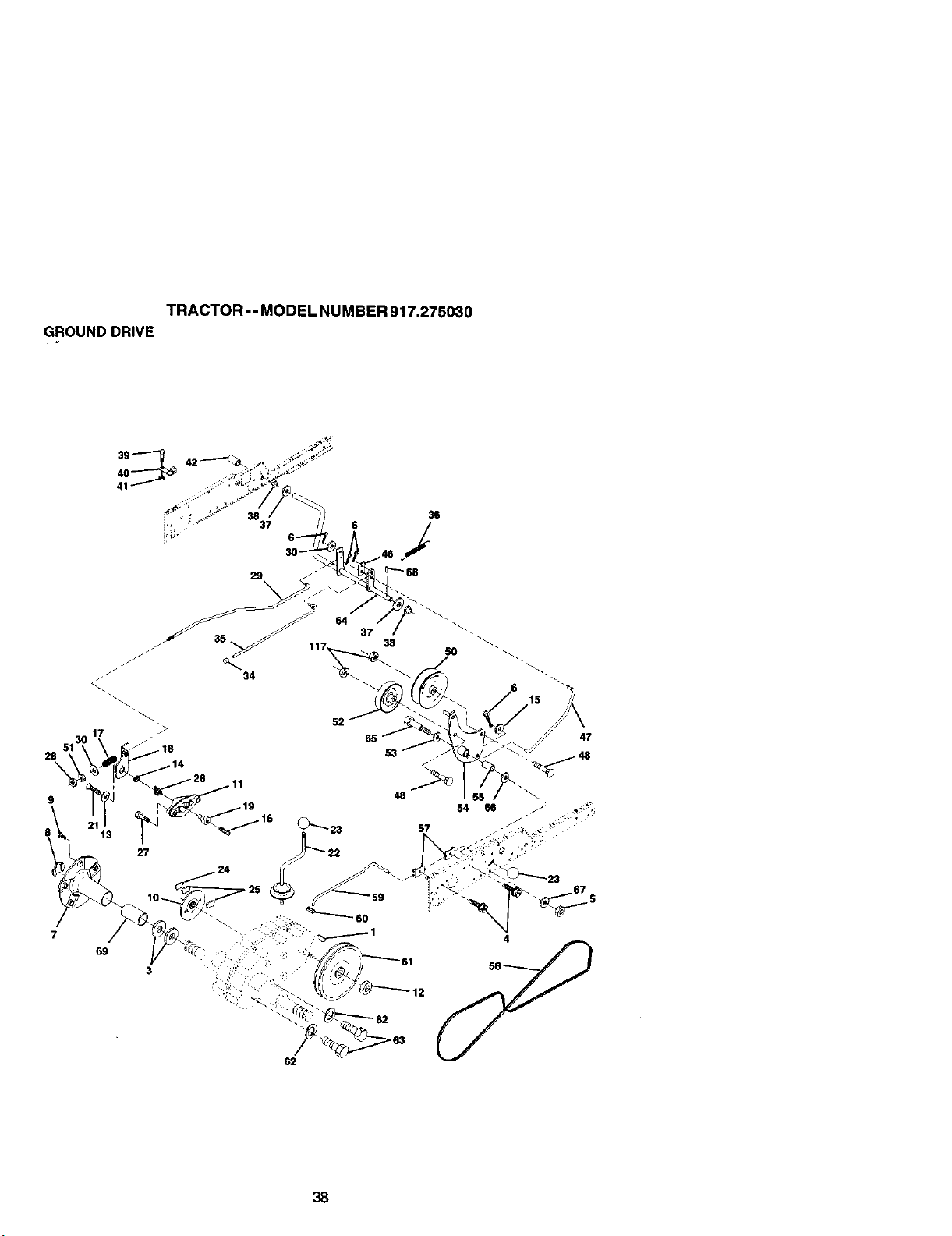
TRACTOR -- MODEL NU MBER 917.275030
GROUND DRIVE
39
36
_', 37 6 I
62
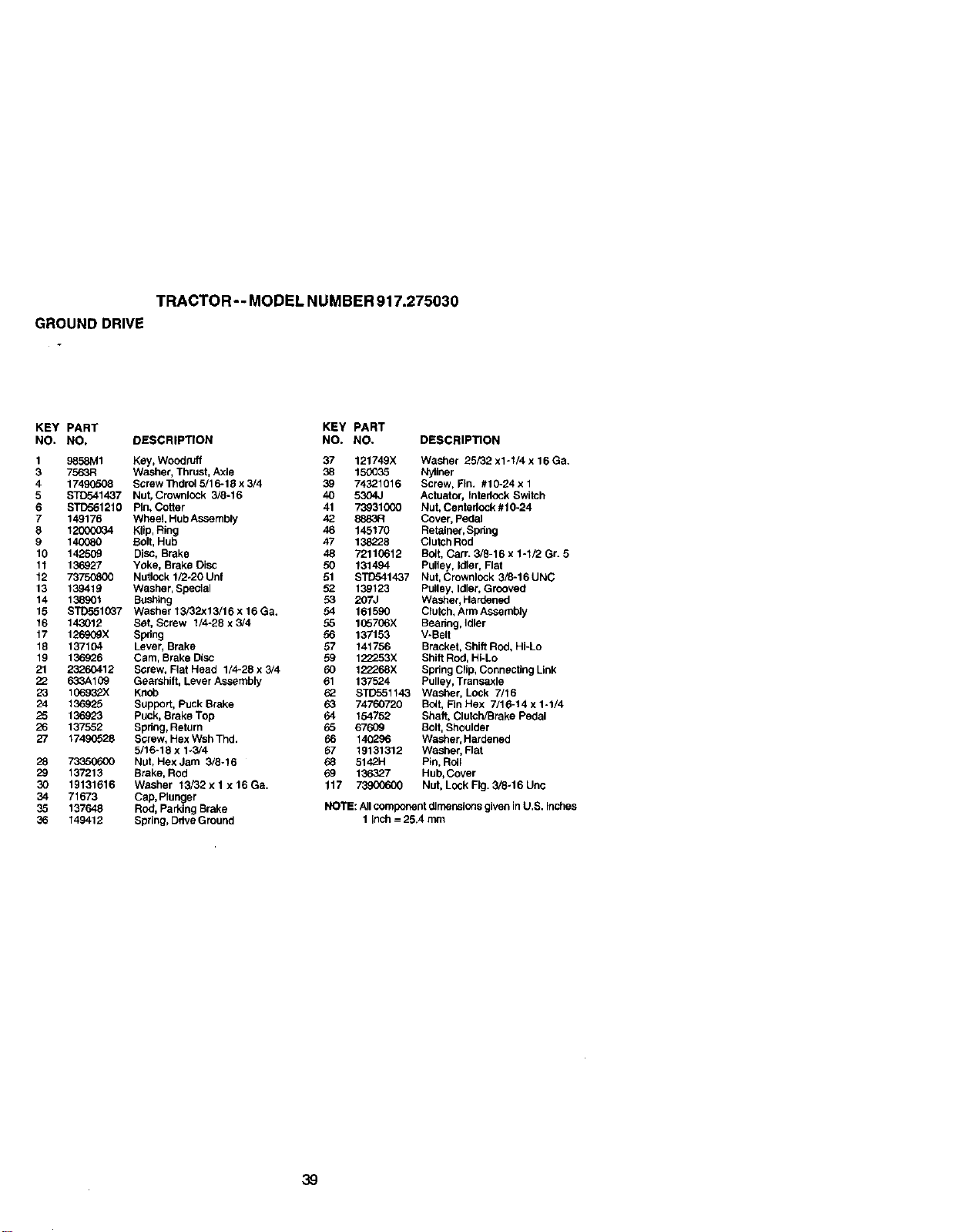
TRACTOR - - MODEL NUMBER 917.275030
GROUND DRIVE
KEY PART KEY PART
NO. NO. DESCRIPTION NO. NO. DESCRIPTION
1 9858M1 Key, Woodruff 37 121749X Washer 25/32 x1-1/4 x 16 Ga.
3 7563R Washer, Thrust, Axle 38 15_035 Nyliner
4 17490508 Screw ThdrOl 5/16-18 x 3/4 39 74321016 Screw, Fin. #10-24 x 1
5 STC541437 Nut, Crownlock 3/8-16 40 5304J Actuator, Interlock Switch
6 STD561210 Pin, Cotter 41 73931000 Nut. Centedock #10-24
7 149176 Wheel, HubAssembly 42 8883R Cover, Pedal
8 12B(X3034 Klip, Ring 46 145170 Retainer,Spdng
9 140080 Bdlt, Hub 47 138228 Clutsh Rod
10 142509 DiSC,Brake 48 72110612 Bolt, Carr. 3/8-16 x 1-1/2 Gr. 5
11 136927 Yoke, Brake Disc 50 131494 Pulley, Idler, Flat
12 73750800 Nutlock 1/2-20 Unf 51 s'rD541437 Nut, Crownlock 3/8-16 UNC
13 139419 Washer, Special 52 139123 Pulley, Idler, Grooved
14 138901 Bushing 53 207J Washer, Hardenod
15 S_1037 Washer 13/32x13/16 x 16 Ga. 54 161590 Clutch, Arm Assembly
16 143012 Sot, Screw 1/4-28 x 3/4 55 1C5706X Beadeg, Idler
17 126909X Spdng 56 137153 V-Belt
18 137104 Lever, Brake 57 141756 Bracket, Shift ROd, Hi-Lo
19 136926 Cam, Brake Disc 59 122253X Shift Rod, Hi-Lo
21 23260412 Screw, Fiat Head 1/4-28 x 3/4 60 122268X Spring Clip, Connecting Link
22 633A109 Gearshift, Lever Assembly 61 137524 Pulley, Transaxle
23 1G693__X Knob 62 STD551143 Washer, Lock 7/16
24 136925 Support, Puck Brake 63 74760720 Boft, Fin Hex 7/16-14 x 1-1/4
25 136923 Puck, Brake Top 64 154762 Shaft, Clutch/Brake Pedal
26 137552 Spdeg, Return 65 67609 Bolt, Shoulder
27 17490528 Screw, Hex Wsh Thd. 66 140296 Washer, Hardened
5/16-18 x 1_3/4 67 19131312 Washer, Rat
28 73350600 Nut, Hex Jam 3/8-16 68 5142H Pin, Roll
29 137213 Brake, Rod 69 136327 Hub, Cover
30 19131616 Washer 13/32 x 1 x 16 Ga. 117 _ Nut, Lock Fk3.3/8-16 Unc
34 71673 Cap, Plunger
35 137648 Rod, Parking Brake NOTE: All component dJrnensionsgiven In U.S. Inches
36 149412 Spring, Ddve Ground 1 inch = 25.4 n_n
39
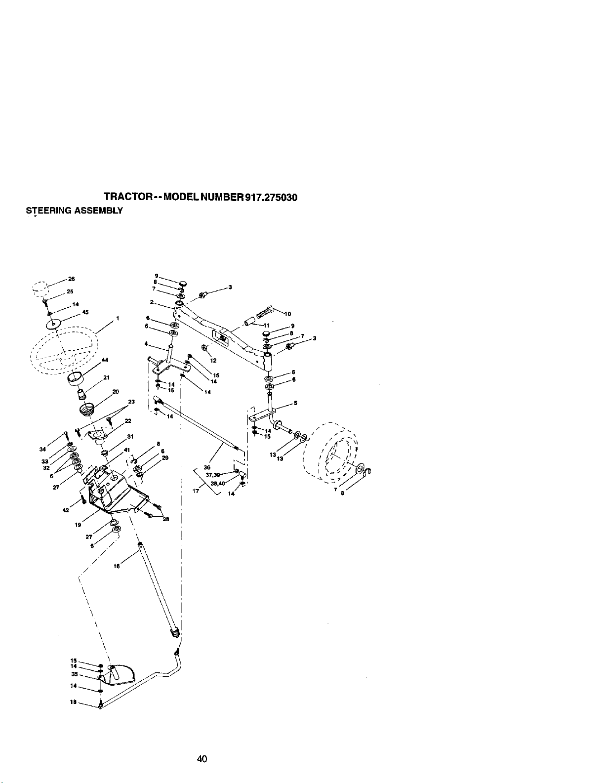
TRACTOR-- MODEL NUMBER 917.275030
STEERING ASSEMBLY
21
34
42
19
6
/
/ 16
\
\
\
\
\
\
23
17
1313_
14
40
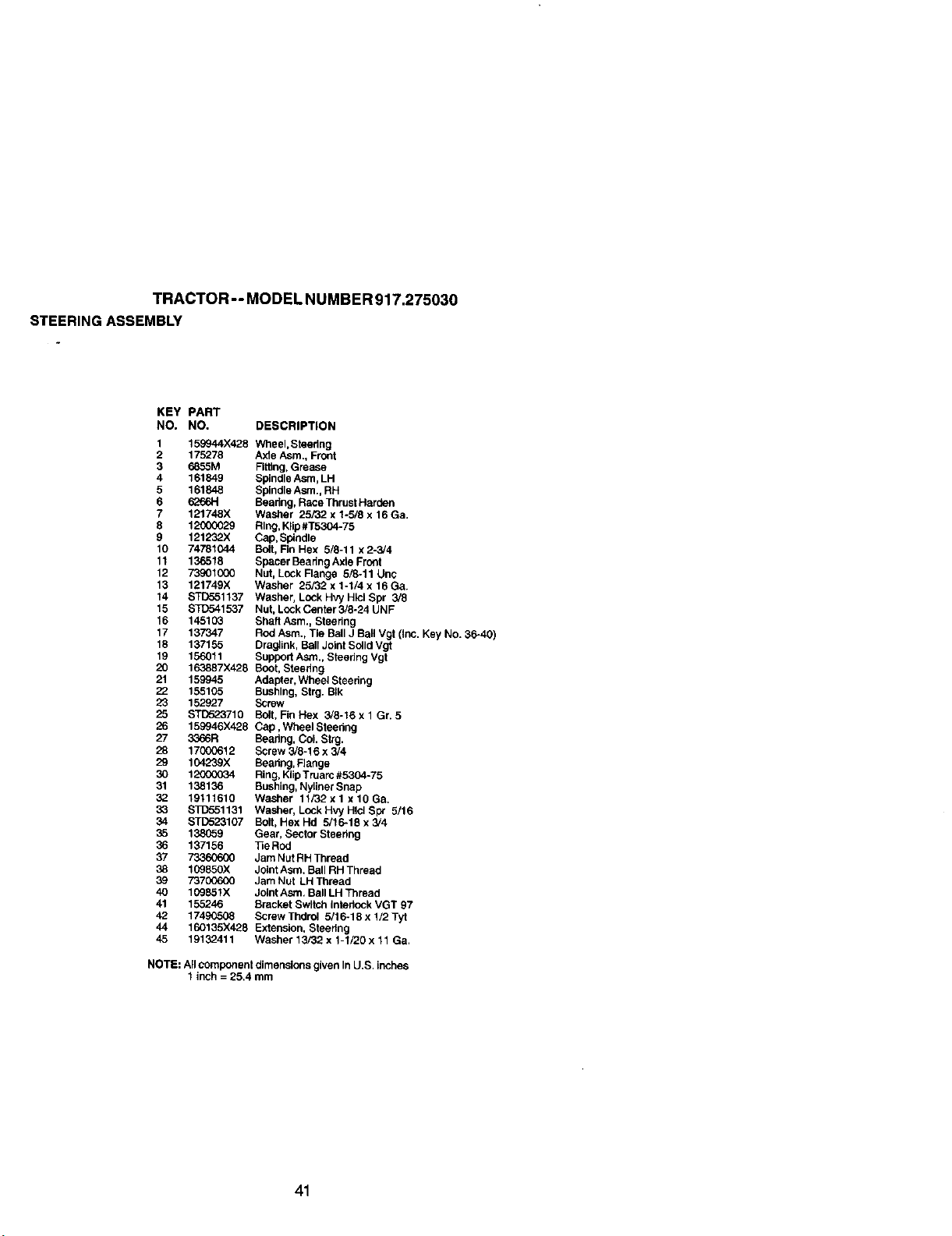
TRACTOR - - MODEL NUMBER 917.275030
STEERING ASSEMBLY
KEY PART
NO. NO. DESCRIPTION
1 159944X428 WheeI,Steedng
2 175278 Axle Asm., Front
3 6855M FIttlng, Grease
4 161849 Spindle Asm, LH
5 161848 Spindle Asm., RH
6 6266H Beadng, Race Thrust Harden
7 121748X Washer 25/32 x 1-5/8 x 16 Ga.
8 12(X)0029 Ring, Klip#T5304-75
9 121232X Cap, Spindle
10 74781044 Bolt, Fin Hex 5/6-11 x 2-3,/4
11 136518 Spacer Baaring Axle Front
12 73901000 Nut, Lock Flange 5/8-11 Unc
13 121749X Washer 25/32 x 1-1/4 x 16 Oa.
14 STD551137 Washer, Lock Hvy HIOl Spr 3/8
15 STD541537 Nut, Lock Center 3/8-24 UNF
16 145103 Shaft Asm., Steering
17 137347 Rod Asm., Tie Ball J Ball Vgt (Inc. Key NO. 36-40)
18 137155 Dra_ink, Ball Joint Solid Vgt
19 156011 Support Asm., Steehng Vgt
20 163887X426 Boot, Steedng
21 159945 Adapter.Wheel Steedng
22 155105 Bushing, Strg. BIk
23 152927 Screw
25 BTD523710 Bolt, FinHex 3/8-16xl Gr. 5
26 159946X428 Cap, Wheel Steering
27 3366R Bearing, CoL Strg.
28 17000612 Screw 3/8-16 x 3/4
29 104239X Beadng, Range
30 12000034 Ring, Klip Truarc #5304-75
31 138136 Bushing, Nyliner Snap
32 19111616 Washer 11/82x 1 x 16 Ga.
33 $3]_551131 Washer, Lock Hvy HIsi Spt 5/16
34 STD523107 Bolt, HexHd 5/16-18x3/4
35 138_59 Gear, Sector Steering
36 137156 33eRod
37 73360600 Jam Nut RH Thread
38 10985oX Joint Asm. Ball RH Thread
39 73700600 Jam Nut LH Thread
40 109851X Joint Asm, Ball LH Thread
41 155246 Bracket Switch Interlock VGT 97
42 17490508 Barew Thdrol 5/16-18 x 1/2 Tyt
44 160135X428 Extension, Steering
45 19132411 Washer 13/32 x 1-1/20 x 11 Ga.
NOTE: All component dimensions given In U.S. inches
1 inch = 25,4 mm
41
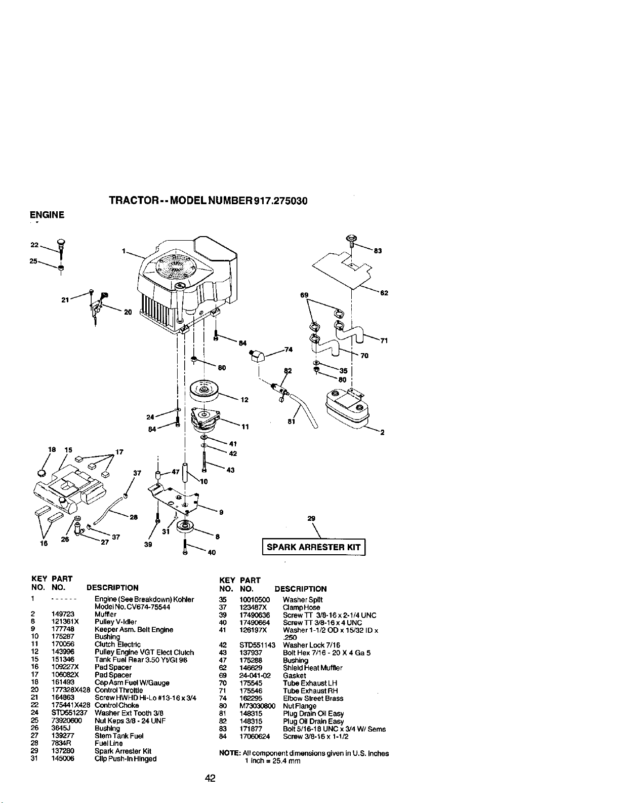
ENGINE
TRACTOR - - MODEL NUMBER 917.275030
18
17
15
37
39
16 _737
81
59
\
ISPARKARRESTERKIT I
KEY PART
NO. NO. DESCRIPTION
1 Engine (See Breakdown) Kohler
Model No. CV674-75544
2 149723 Muffler
8 121361X PuUey V-Idler
9 177748 Keeper Asm. Belt Engine
10 175287 Bushing
11 170056 Clutch Electric
12 143996 Pulley Engine VGT Elect Clutch
15 151346 Tank Fuel Rear 3.50 Yt/Gt 96
16 108227X Pad Specer
17 108082X Pad Spacer
18 161493 CapAsm Fuel W/Gauge
20 177328X426 Control Throltle
21 164863 Screw HWHD Hi-Lo #13-16 x 3/4
22 175441X428 Contrct Choke
24 STD551237 Washer Ext Too_ 3/8
25 73920600 Nut Ke_ _- 24 UNF
26 384_ Bushing
27 139277 Stem Tank Fuel
28 7834R Fuel Line
29 137280 Spark Arrester Kit
31 145006 Clip Push-In HFnged
42
KEY PART
NO. NO. DESCRIPTION
18012800 Washer Split
37 12_87X ClampHc_e
17490636 Screw _ 3/8-16 x 2-1/4 UNC
40 17490664 Screw Tr 3/8-16x4 UNC
41 126197X Washer 1-1/20D x 15/32 ID x
.250
42 STD551143 Washer Lock 7/16
43 137937 Bolt Hex 7/16 - 20 X 4 Ga 5
47 175288 Bushing
62 146629 Shield Heat Muffler
2_041_ Gasket
70 175545 TUpe Exhaust LH
71 175546 Tube Exhaust RH
74 162295 Elbow Street Brass
80 M730_680 Nut Range
81 148315 Plug Drain Oil Easy
82 148315 Plug Oil Drain Easy
83 171877 BO_t5/16-18UNCx3/4W/Sems
84 17060624 Screw 3/8-16 x 1-1/2
NOTE: All component dimensions given in U.S. inches
1 inch = 25.4 mm
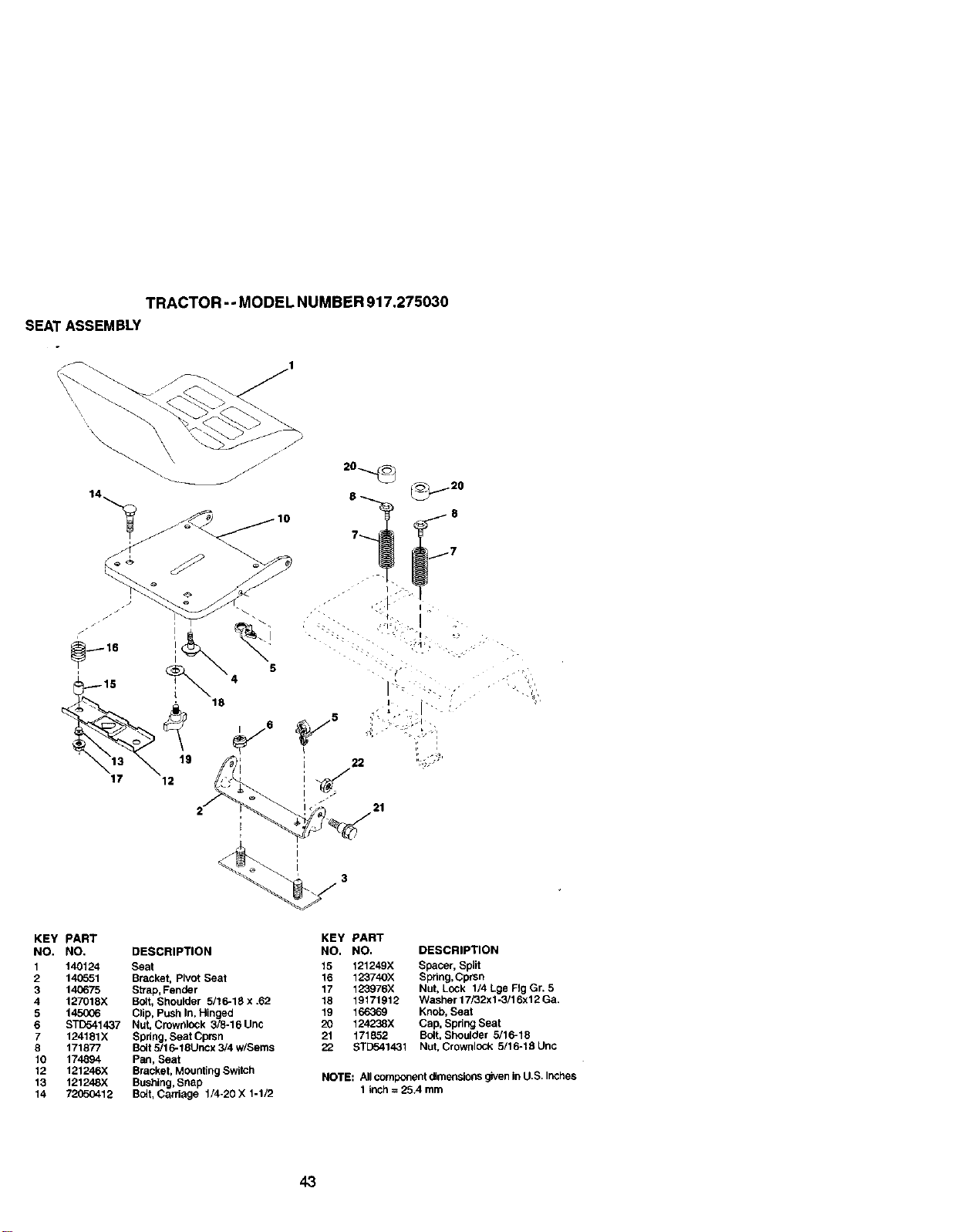
TRACTOR -oMODEL NUMBER 917.275030
SEAT ASSEMBLY
21
KEY PART
NO. NO. DESCRIPTION
1 140124 Seat
2 14G651 Bracket, Pivot Seat
3 140675 Strap, Fender
4 127018X Bolt, Shoulder 5/16-18 x .62
5 1450G6 Clip, Push In, Hinged
6 STD541437 Nut, Crownlock 3/8-16Unc
7 124181X Spdng, Seat Cprsn
8 171877 Bolt 5/1 6-18Uncx 3/4 w/Seres
10 174894 Pan, Seat
12 121246X Bracket, Mounting Switch
13 121248X Bushing, Snap
14 72050412 Bolt, Carriage 1/4-20 X 1-1/2
KEY PART
NO. NO. DESCRIPTION
15 121249X Spacer, Split
16 123740X Spdng,Cprsn
17 123976X Nut, Lock 1/4 Lge Fig Gr. 5
18 19171912 Wacher17i32xl-3/16x12Ga.
19 166369 Knob, Seat
20 124238X Cap, Spring Seat
21 171852 Bolt, Shoulder 5/16-18
22 STE_o41431 Nut, Crownlock 5/16-18Unc
NOTE: Allcomponentdimensionsgivenin U.S.Inches
1 inch: 25,4 mm
43
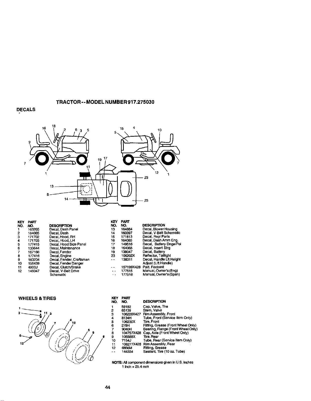
DECALS
TRACTOR - - MODEL NUMBER 917,275030
18
16
2 6
15 4
12
to
13
KEY pART
NO. NO.
1 163265
2 164085
3 1717(_
4 171703
5 177415
6 133644
7 167166
8 177416
9 163204
10 156439
11 4900J
12 146047
DESCRIPTION
Decal, Dash Panel
Decal, Dash
Decal, Hood, RH
Decal, Hood, LH
Decal, Hood Side Panel
Decal, Maintenance
Decal, Fender
Decal, Engine
Decal, Fender, Craftsman
Decal, Fender Danger
Decal, Clutch/Brake
Decal, V-Belt Drive
Schematic
PART
NO. NO. DESCRIPTION
13 164884 Deca], Blower Housing
14 160397 Decal, V-BStt Schematic
15 171813 Decal, Repl Parts
16 164085 Decal, Dash Atom Eng.
17 149516 Decal, Battery Dnge/Po!
18 164065 Decal, Insed Strg
19 138047 DeCal, Battery
23 10620__X Reflector, Taillight
- - 138311 DeCal, Handle Lit Height
Adjust (Lift Handle)
- - 157199X428 Pad, Footrest
- - 177515 Manual,Owner's (Eng)
- - 177516 Manual, Owner's(Span)
WHEELS &TIRES
3
7
4
10
KEY PART
NO. NO. DESCRIP'iION
1 59192 Cap, Valve_ Tire
2 65139 Stem, Valve
3 1(_228X427 Rim Assembly, Front
4 8134H Tube, Front (Service Item Only)
5 106230X Tire, Fro_t
6 2781-1 Fitting, Grease (Front Wheel On_y)
7 _40H Beadng, Range (Front Wheel Only)
8 104757X428 Cap, Axle (Front Wheel Only)
9 1(_588X Tire, Rear
10 7154J Tube, Rear (Service Item Only)
11 106277X428 Rim Assembly, Rear
12 6856M FiRing, Grease
- - 144334 Sealant, _re (10 oz, Tube)
NOTE: All component dimensions given In U.S. inches
1 Inch = 25.4 mrn
44
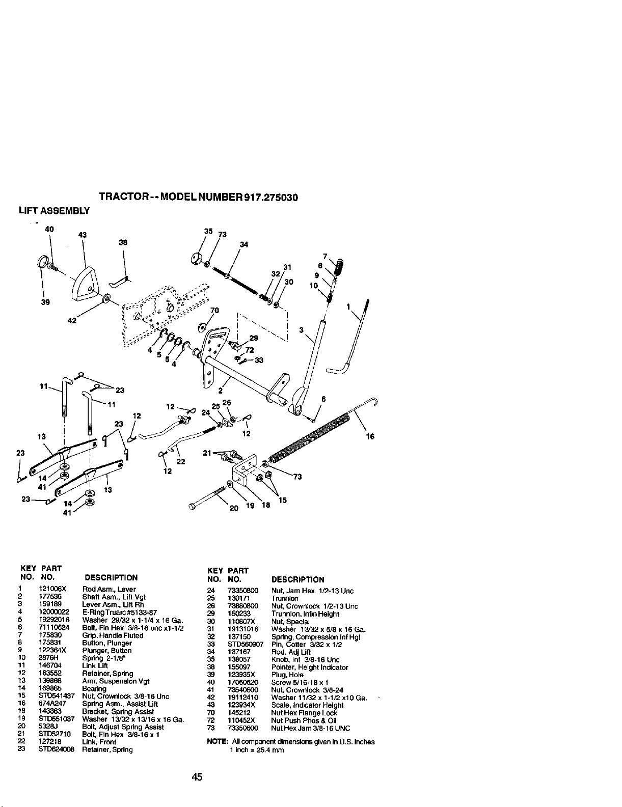
LIFT ASSEMBLY
4O
43
39
42
i
13
23
TRACTOR - - MODEL NUMBER 917.275030
38
35 73
7O
34
31
13
12
22
20 19 18
15
16
KEY PART
NO. NO.
1 121006X
2 177535
3 159189
4 120000_2
9 19292016
6 71110624
7 175830
8 175831
9 122364X
10 2876H
11 146704
12 163552
13 139868
14 169865
15 ST_>41437
16 674A247
18 143363
19 S_3551037
20 5328J
21 STD52710
22 127218
23 STD624008
DESCRIPTION
Rod Asm;, Lever
Shaft Asm. Lift Vgt
Lever Asm. Lift Rh
E-RlngTruarc#5133-87
Washer 29/32 x 1-1/4 x 16 Ga.
Bolt, Fin Hex 3/8-16 unc x1-1/2
Grip, Handle Ruted
Button, Plunger
Plunger, Button
Spring 2-1/8"
Link Lift
Retainer, Spring
Arm, Suspension Vgt
Scaring
Nut, Crownlock 3/8-16 Unc
Spdng Asm., AssLst Lift
Bracket, Spdng Assist
Washer 13/32 x 13/16 x 16 Ga.
Bolt, Adjust Spdng Assist
Bolt, Fin Hex 3/8-16 x 1
Link, Front
Retainer, Spring
KEY PART
NO, NO. DESCRIPTION
24 73350800 Nut, Jam Hex 1/2-13 Unc
25 130171 Trunnton
26 73680800 Nut, Crowdiock 1/2-13 Unc
29 150233 Trunnion, Infin Height
30 11(_07X Nut, Special
91 19131016 Washer 13/32 x 5/9 x 16 Ga.
32 197150 Spdng, Compression Inf Hgt
33 STD56_7 Pin, Cotter 3/32 x 1/2
34 137167 Rod, Adj Lift
35 138057 Knob, Inf 3/8-16 Uric
38 155097 Pointer, Height Indicator
39 123935X Plug, Hole
40 17060620 Screw 5/16-18 x 1
41 73540600 Nut, Crownlock 3/8-24
42 19112410 Washer 11/32 x 1-1/2 xlO Ga.
43 123934X Scale, Indicator Height
70 145212 Nut Hex Flange Lock
72 110452 Nut Push Phos & Oil
73 73350600 Nut Hex Jam 3/8-16 UNC
NOTE: All component dimensions given in U.S. itches
1 inch = 25.4 mm
45
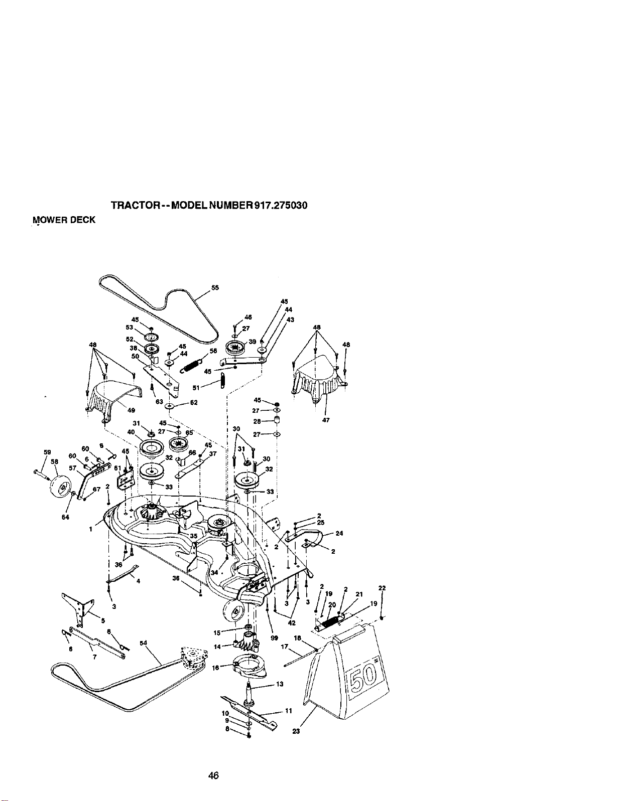
TRACTOR - - MODEL NU MBE R917.275030
MOWER DECK
48
55
46
45
48
59
64
22
46
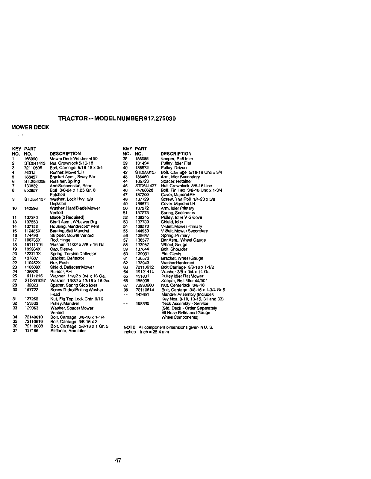
TRACTOR - - MODEL NUMBER 917.275030
MOWERDECK
KEY PART KEY PART
NO, NO, DESCRIPTION NO. NO.
1 156990 Mower Deck Weldment 50 38 156085
2 STD541413 Nut, Crownlock 5/16-15 39 131494
3 72110506 Bolt, Cardage 5/16-18 x 3/4 40 136572
4 7631J Runner, Mower LH 42 STD533107
5 138457 Bracket Asm., Sway Bar 43 136460
6 STD624008 Retainer, Spdng 44 165723
7 130832 Arm Suspension, Rear 45 STID541437
8 850857 Bolt 3/8-24 x 1.25 Gr. 8 46 74760628
Patched 47 137200
9 STD551137 Washer, Lock Hvy 3/8 48 137729
Unplatsd 49 136574
10 14(729_ Washer, Hard Blade Mower 50 137272
Vented 51 137273
11 137380 Blade (3 Required) 52 139245
13 137553 Shaft Asm., W/Lower Brg 53 137789
14 137152 Housing, Mandrel 50" Vent 54 139573
15 110485X Beadng, Ban Mandrel 55 144959
16 174493 Stripper, Mower Vented 56 138687
17 106735X Rod, Hinge 57 136577
18 19111016 Washer 11/32 x 5/8 x 16 Ga. 58 133957
19 105304X Cap, Sleeve 59 137644
20 123713;< Spring, Torolon Deflector 60 139031
21 137607 Bracket, Deflector 61 136573
22 110452X Nut, Push 62 133943
23 110509X Shield, Deflector Mower 63 72110612
24 136320 Runner, RH 64 19121414
25 19111216 Washer 11/32 x 3/4 x 16 Ga. 65 151831
27 STD5510_7 Washer 13/32x13/16x16Ga. 66 156669
28 132823 Spacer, Spring S_p Idler 67 73930600
30 157722 Screw Thdrol Rolling Washer 99 72110614
Head - - 143651
31 137266 Nut, Fig Top Lock Cntr 9/16
3_ 153535 Pulley, Mandrel - - 158330
33 129963 Washer, Spacer Mower
Vented
34 72140610 Bolt, Carriage 3/8-16 X 1-1/4
35 72110616 Bolt, Carriage 3/8-16 x 2
36 72110608 Bolt, Cardage 3/8-16 x 1 Gr. 5
37 137166 Sflffener, Arm Idler
DESCRIPTION
Keeper, Belt idler
Pulley, Idler Flat
Pulley, Ddven
Bolt, Cardage 5/16-18 Unc x 3/4
Arm, Idler Secondary
Spacer, Retainer
Nut, Crownlock 3/8-16 Unc
Bolt, Fin Hex 3/8-16 Uric x 1-3/4
Cover, Mandrel RH
Screw, Thd Roll 1/4-20 x 5/8
Cover, Mandrel LH
Arm, Idler Pdmary
Spnng, Secondary
Pulley, Idler V Groove
Shield, Idler
V-Belt, Mower Primary
V-Belt, Mower Secondary
Spdng, Pdmary
Bar Asm., Wheel Gauge
Wheel,Gauge
Bolt, Shoulder
Pin, Clevis
Bracket, Wheel Gauge
Washer Hardened
Bolt Cardage 3/8-16 x 1-1/2
Washer 3/5 x 3/4 x 14 Ga
Pulley Idler Rat Mower
Keeper, Belt Idler 44/50"
Nut, Centedock 3/8-16
Bolt, Cardage 3/8-16 x 1-3/4 Gr.5
Mandrel Assembly (includes
Key Nos. 8-10, 13-15, 31 and 33)
Deck Assembly - Service
(Std. Deck - Order Separately
All Nose Roller and Gauge
Wheel Components)
NOTE: All component dimensions given In U. S.
inches 1 inch = 25.4 mm
47
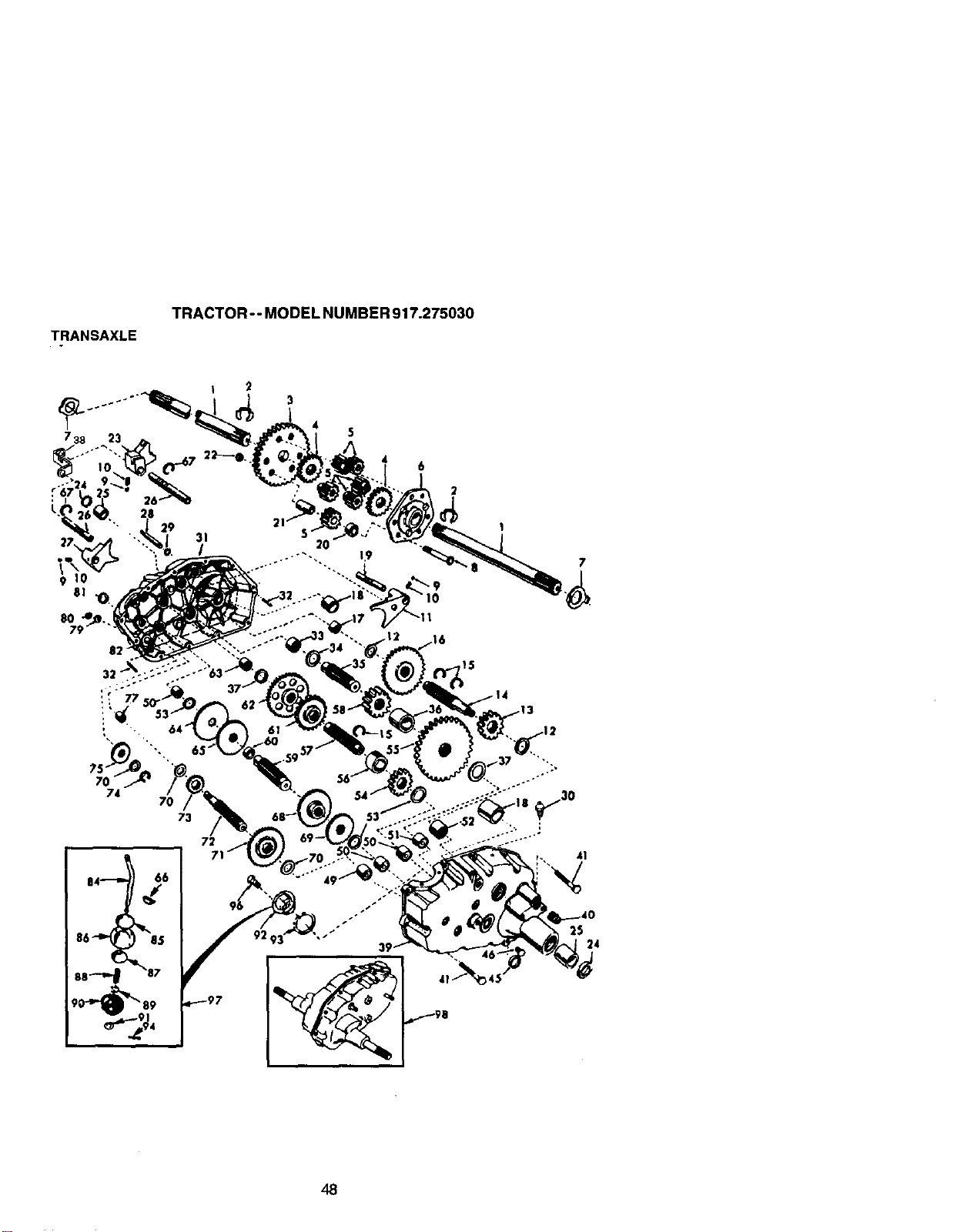
TRANSAXLE
TRACTOR- - MODEL NUMBER 917.275030
8O
8;
32
74
B4-_ 66
86 8.5
88 7
73
72
6
41
25
24
48
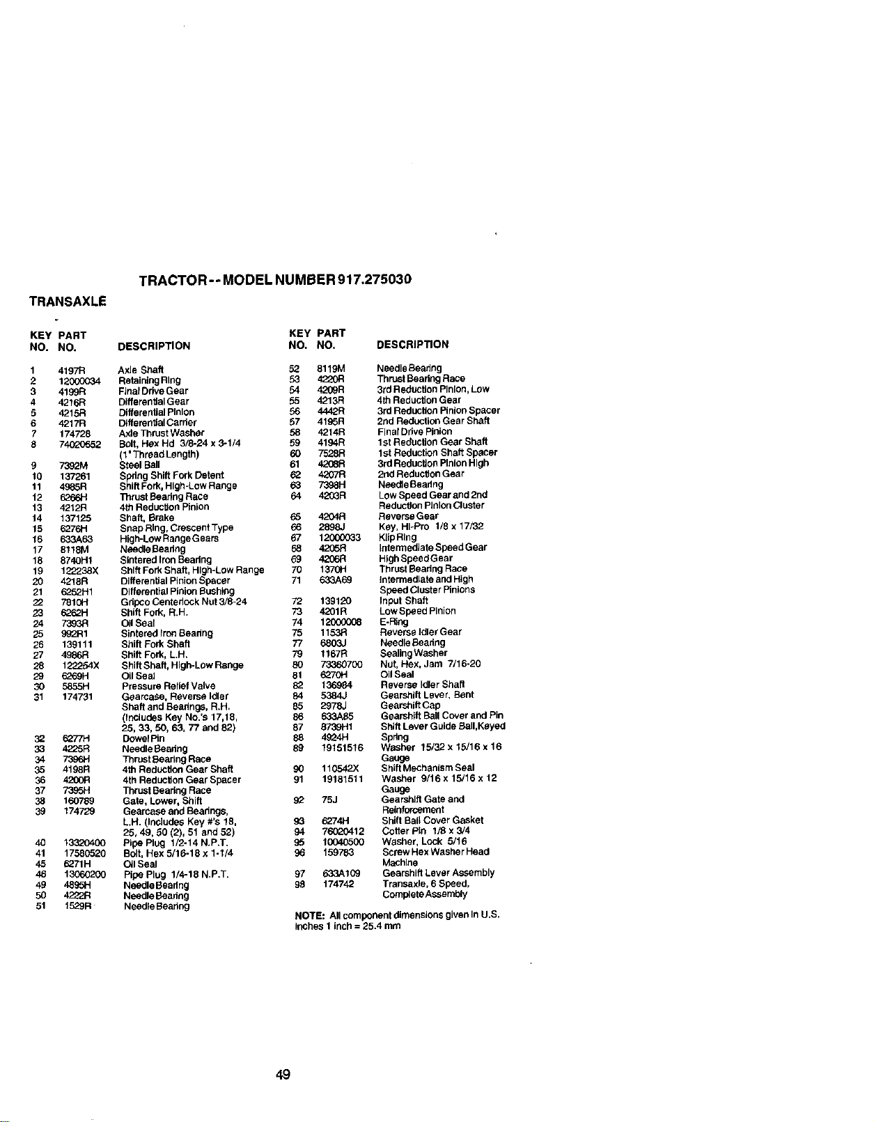
TRANSAXLE
KEY PART
NO. NO.
1 4197R
2 121300034
3 4199R
4 4216R
5 4215B
6 4217R
7 174728
8 74020652
9 7352M
10 137261
11 49_5R
12 6266H
13 4212R
14 137125
15 5276H
16 633A_3
17 8118M
18 8740H1
19 122238X
20 4218R
21 5252H1
22 7810H
23 6262H
24 7393R
25 992R1
26 139111
27 4986R
28 122254X
29 5252H
3O 5855H
31 174731
32 6_/7H
33 4225R
34 7396H
35 4198R
36 4200R
37 7395H
38 160789
39 174729
40 13320400
41 17580520
45 5271H
46 13065200
49 4895H
50 4222R
51 1529R
TRACTOR-- MODEL NUMBER917.275030
KEY PART
DESCRIPTION NO. NO. DESCRIPTION
Axle Shaft 52 8119M Needle Beadng
Retaining Ring 53 4220R Thrust Beadng Race
Final Drive Gear 54 42_R 3rd Reduction Pinion, Low
Differential Gear 55 4213R 4th Reduclion Gear
Differential Pinion 56 4442R 3rd Reduction Pinion Spacer
D_fferer_tialCarder 57 4195R 2rid Reduction Gear Shaft
Axle Thrust Washer 58 4214R Final Ddve Pinion
Bolt, Hex Hd 3/8-24 x 3-1/4 59 4194R 1st Reduction Gear Shaft
(1' Threed Length) 60 7528R 1st Reduction Shaft Specer
Steel Ball 61 4208R 3rd Reduction Plalon High
Spring Shift Fork Detent 63 4207R 2nd Reduction Gear
Shift Fork, High-Low Range 63 7398H Needle Beedng
13_rustBaadng Race 64 4203R Low Speed Gear and 2nd
4th Reduction Pinion Reducgon Pinion Cluster
Shaft, Brake 65 4204R Reverse Gear
SnapRIng, Creecent Typo 66 2898J Key, HI-Pro 1/8 x 17/32
High-Low ReegeGears 97 12(]00033 Kltp Ring
Needle Beadng 68 4205R Intennealate Speed Gear
Sintered Iron Seadng 69 4206R High SpeedGear
Shill Fork Shaft, High-Low Range 70 1370H Thrust Beadng Race
Differential Pinion Spacer 71 633A69 Intermediate and High
Differential Pinion Bushing Speed Cluster Pinions
Gdpco Cerdedock Nut 3/8-24 72 139120 Input Shall
Shift Fork, R.H. 73 4201R LowSpeed Pinion
Oil Seal 74 12000008 E-I_ng
Sintered Iron Beadng 75 1152R Reverse Idler Gear
Shift Fork Shaft 77 6803J Needle Beadng
Shift Fork, L.H. 79 1167R SeelingWasher
Shill Shaft, High-Low Range 80 73360700 Nut, Hex, Jam 7/15-20
Oil Seal 81 5270H Oil Seal
Pressure Relief Valve 82 136984 Reverse Idler Shaft
Gearcase, Reverse Idler 84 5384J Gearshift Lever, Bent
Shaft and Beadng_, R.H. 85 2978J Gearshift Cap
(Includes Key No.'s 17,18, 86 633A85 Gearshift Ball Cover and Pin
25, 33, 50, 63, 77 and 82) 87 8739H1 Shift Lever Guide Bali,Keyed
Dowel Pin 88 4524H Spdng
NeedleBaadng 89 19151516 Washer 15/32 x 15/16 x 16
Thrust Bearing Race Gauge
4th Reduction Gear Shaft 90 110542X Shift Mechanism Seal
4thReductionGearSpacer 91 19181511 Washer 9/16x 15/16 x 12
Thrust Bearing Race Gauge
Gate, Lower, Shift 92 75J Gearshift Gate and
Gearceee and Bearings, Reinforcement
L.H. (Inc]upee Key #'s 18, 93 5274H Shift Ball Cover Gasket
25, 49, 50 (2), 51 and 52) 94 76020412 Cofter Pin 1/8 x 3/4
Pipe Plug 1/2-14 N.P.T. g5 10040500 Washer, Lock 5/19
Bolt, Hex 5/16-18 x 1-1/4 g6 159783 Screw Hex Washer Head
Oil Seal MaChine
Pipe Plug 1/4-18 N.P.T. 97 633A109 Gearshift Lever Assembly
Needle Beadng 98 174742 Transaxle, 6 Speed,
Needle Baadng Complete Assembly
Needle Beadng
NOTE: All component dimensions given In U.S.
inches 1 inch = 25.4 mm
49
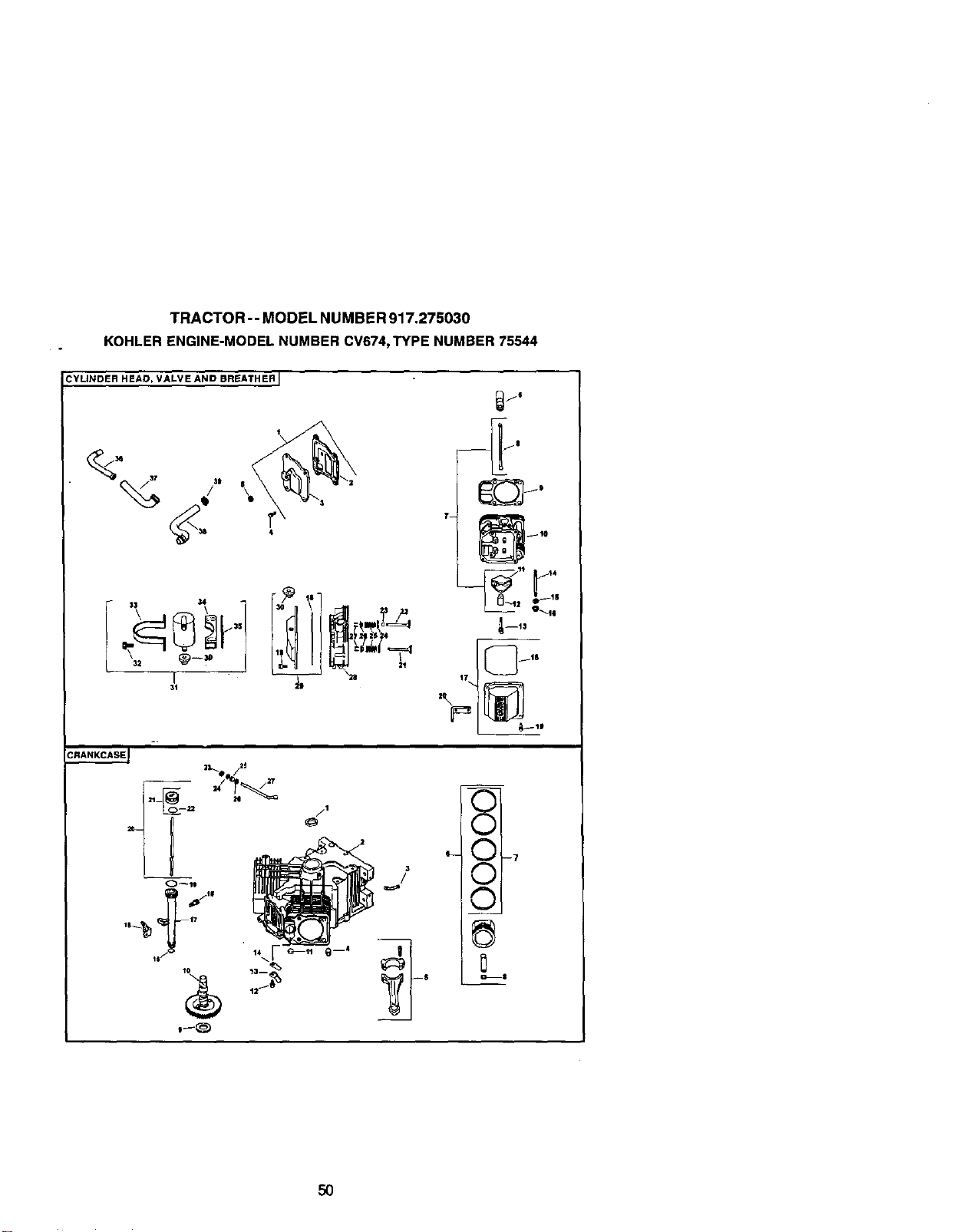
TRACTOR -- MODEL NUMBER 917.275030
KOHLER ENGINE-MODEL NUMBER CV674,TYPE NUMBER 75544
CYLINDER HEAD, VALVE AND BREATHER I
T_
17
j6
4--t5
E
X r-_
5o
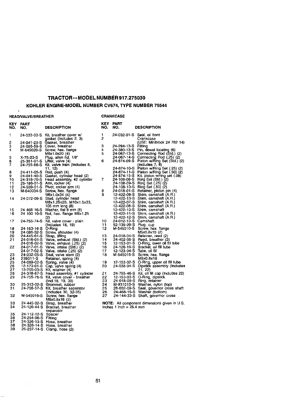
TRACTOR -- MODEL NUMBER 917.275030
KOHLER ENGINE-MODEL NUMBER CV674, TYPE NUMBER 75544
HEAD/VALVE/BREATHER
CRANKCASE
KEY PART KEY PART
NO. NO. DESCRIPTION NO. NO. DESCRIPTION
1 24-033-03-S Kit, breather cover w/ t 24-032-01-S Seal, oil front
gasket (Includes 2, 3) 2 Crankcase
2 24-041-23-S Gasket, breather USE: Miniblock 24 782 14)
3 24-096-59-S Cover, breather 3 24-294°13-S Fittin
4 M-645020-S Screw, hex, flange 4 24-380-13-S Pin, dowel locating (6)
M6xl.0x20 4 5 24-067-13-S Connecting Rod (Std.) (2)
5 X-75-23-S Plug, allen hd. 1/8" 24-067-f4-S Connecting Rod (.25) (2)
6 25-351-0f-S Lifter, valve (4) 6 24-874-09-S Piston w/Ring Set (Std.) (2
7 24-755-66-S Kit, valve train (Includes 8, (Includes 7, 8
11, 12) 24-874-10-S Piston w/Ring Set (.25 2)
8 24-411-05-S Rod, push (4) 24-874-11-S Piston w/Ring Set (.50 2)
9 24-041-40-S Gasket. cy}inder head (2) 24-874-15-S Kit, piston w/ring set (.08)
t0 24-318-70-S Head assembly, #2 cylinder 7 24-108-08-S Ring Set (Std.) (2)
f 1 25-186-01-S Arm, rocker (4 24-f08-09-S Ring Set (.25) (2)
12 24-599-01-S Pvot, rocker arm 4) 24-108-10-S Ring Set .50) (2)
13 M-640034-S Screw, hex. flange 8 24-018-01-S Retainer, piston pin (4)
M6xl.0x34 (4) 9 12-422-09-S Shim, camshaft (A.R.)
14 24-072-09-S Stud, cylinder head 12-422-13-S Shim, camshaft (A.R.)
MSx1.25x20, M10x1.5x33, 12-422-07-S Shim, camshaft A.R.)
105 mm long (8) 12-422-08-S Shim, camshaft A.R.
15 24 468 16-S Washer, flat 8 mm (8) 12-422-10-S Shim, camshaft
16 24 100 10-S Nut, hex. flange M8x1.25 12-422-11-S Shim, camshaft (A.R.)
(2) 12-422-t2-S Shim, camshaft (A.R.)
17 24-755-74-S Kit, valve cover- plain 10 24-012-10-S Camshaft
(Includes 18, 19) 11 52-139-09-S Plug, cup
18 24-153-16-S O-Ring 12 M-545010-S Screw, hex. flange
19 24-086-32-S Screw, shoulder (4) M5x0.Sxl0 (2)
20 24-445-01-S Strap, lifting 13 24-018-04-S Retainer, reed (2)
21 24-016-01-S Valve, exhaust (Std.) (2) 14 24-402-05-S Reed, breather (2)
24-016-02-S Valve, exhaust (.25) (2) 15 12-153-01-S O-Ring, lower oil fill tube
16 24-126-19-S Bracket, oil fill tube
22 24-017-01-S Valve, intake (Std.) (2)
24-017-02-S Valve, intake (.25) (2) 17 12-123-04-S Tube, oil fill
23 24-032-05-S Seal, valve stem (2) 18 M-545016-S Screw, hex. flange
24 235011-S Retainer, spring (4) M5xO.8x16
25 24-089-02-S Spring, valve (4 19 12-133-02-S O-Ring, upper oil fill tube
26 12-173-01-S Cap, valve spring (4) 20 24-038-04-S Dipstick assembly (Includes
27 12-755-03-S Kit, retainer (4) 21, 22)
28 24-318-67-S Head assembly. #1 cylinder 21 24-755-46-S Kit, oil fill cap (Includes 22)
29 24-755-76-S Kit, valve cover - breather 22 12-153-03-S O-Ring, dipstick
(Ioc1.18, 19, 30) 23 24-018-09-S Ring, retainer
30 25-313-02-S Grommet, rubber 24 M-931010-S Washer, nylon (top)
31 24-755-57-S Kit, breather separator 25 28-032-09-S Seal, governor cross shaft
(Includes 30, 32-35) 26 24-468-15-S Washer (bottom)
32 M-545016-S Screw, bex. flange 27 24-144-33-S Shaft, governor cross .
M5x0.8xl 6 (2)
33 24-445-02-S Strap, breather NOTE: All component dimensions given in U.S.
34 24-126-44-S Bracket, breather inches 1 inch = 25.4 mm
separator
35 24-112-12-S S acer
36 24-294-06-S F_ing
37 24-326-13-S Hose, breather
38 24-326-14-S Hose, breather
39 25-237-14-S Clamp, hose (2)
51
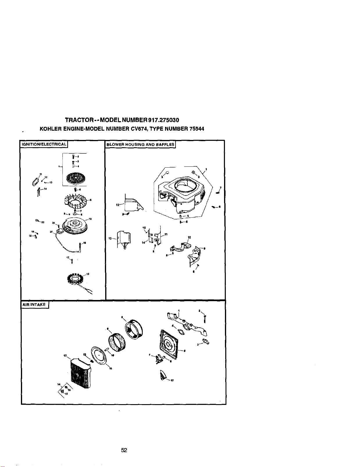
TRACTOR - - MODEL NUMBER 917.275030
KOHLER ENGINE-MODEL NUMBER CV674, TYPE NUMBER 75544
IGNITIONIELECTRICAL I
@
BLOWER HOUSING AND BAFFLESJ
AIR INTAKE J
14 |
52
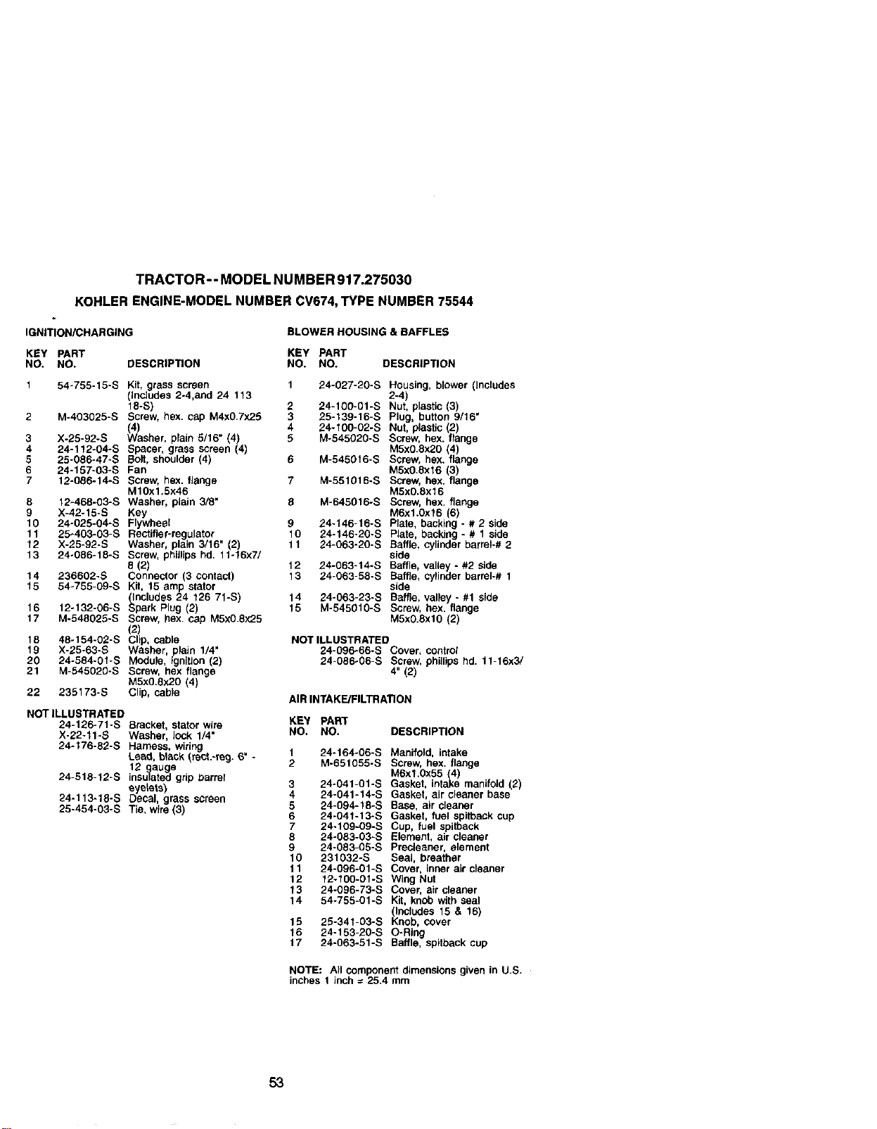
TRACTOR-- MODEL NU MBER 917.275030
KOHLER ENGINE-MODEL NUMBER CV674, TYPE NUMBER 75544
IGNITION/CHARGING BLOWER HOUSING & BAFFLES
KEY PART KEY PART
NO. NO. DESCRIPTION NO. NO. DESCRIPTION
1 54-755-15-S Kit, grass screen 1 24-027-20-S Housing, blower (includes
(Includes 2-4,and 24 113 2-4)
18-S) 2 24-100-01-S Nut, plastic (3)
2 M-403025-S Screw, hex. cap M4xO,7x2.5 3 25-139-16-S Plug, button 9/16"
(4) 4 24-fOO-02-S Nut, plastic 2)
3 X-25-92-S Washer, plain 5/16" (4) 5 M-545020-S Screw, hex. fange
4 24-112-04-S Spacer, grass screen (4) M5x0.8x20 (4
5 25-086-47-S Bolt, shoulder (4) 6 M-545016-S Screw, hex. fange
6 24-157-03-S Fan M5x0.8x16 (3)
7 12-08B-14-S Screw, hex. flange 7 M-551016-S Screw, hex. flange
M1gx1.Sx46 MSxO.Sx16
8 12-468-03-S Washer, plain 3/8" 8 M-645016-S Screw, hex. flange
9 X-42-15-S Key M6xl.Oxf 6 (6)
10 24-025-04-S Flywheel 9 24-146-16-S Plate, backing - # 2 side
11 25-403-03-S Rectifier-regulator 10 24-146-20-S Plate, backing - # 1 side
12 X-25-92-S Washer, plain 3/16" (2) 11 24-063-20-S Baffle, cylinder barrel-# 2
13 24-086-18-S Screw, phillips hd. 11-16x7/ side
8 (2) 12 24-063-14-S Baffle, valley - #2 side
14 236602-S Connector (3 contact) 13 24-063-58-S Baffle, cylinder barrel-# 1
15 54o755-09-S Kit, 15 amp stator side
(Includes 24 126 71-S) 14 24-063-23-S Baffle, valley - #1 side
16 12-132-06-S Spark Plug (2) 15 M-54501g-s Screw, hex. flange
17 M-548025-S Screw, hex. cap M5x0.8x2.5 M5x0.8xlO (2)
(2)
18 48-154-02-S Clip, cable NOT ILLUSTRATED
19 X-25-63-S Washer, plain 1/4" 24-096-66-S Cover, control
20 24-584-0t-S Module, ignition (2) 24-086o06-S Screw, phillips hd. 11-16x3/
21 M-545020-S Screw, hex flange 4" (2)
M5x0.Sx20 (4)
22 235173-S Clip, cable
AIR INTAKE/FILTRATION
NOT ILLUSTRATED
24-126-71-S Bracket, stator wire
X-22-11-S Washer, lock 1/4"
24-176-82-S Harness, wiring
Lead, black (rect.-re9. 6" -
12 gauge
24-518-t2-S insulated grip barrel
eyelets)
24-113-18-S Decal, grass screen
25-454-03-S Tie, wire (3)
KEY PART
NO. NO. DESCRIPTION
t 24-164_06-S Manifold, intake
2 M-651055-S Screw, hex. flange
M6xl.0x55 (4)
3 24-041-01-S Gasket, intake manifctd (2)
4 24-041-14-S Gasket, air cleaner base
5 24-094-18-S Base, air cleaner
6 24-041-13-S Gasket, fuel spitback cup
7 24-109-09-S Cup, fuel apitback
8 24-083-03-S Element, air cleaner
9 24-083-05-S Precteaner, element
10 231032-S Seal, breather
11 24-g96-01-S Cover, inner air cleaner
12 12-fO0-0f-S Wing Nut
13 24-096-73-S Cover, air cleaner
14 54-755-01-S Kit, knob with seal
(Includes 15 & 16)
15 25-341-03-S Knob, cover
16 24-153-20-S O-Ring
17 24-063-51-S Baffle, spitback cup
NOTE: All component dimensions given in U.S.
inches 1 inch = 25.4 mm
53
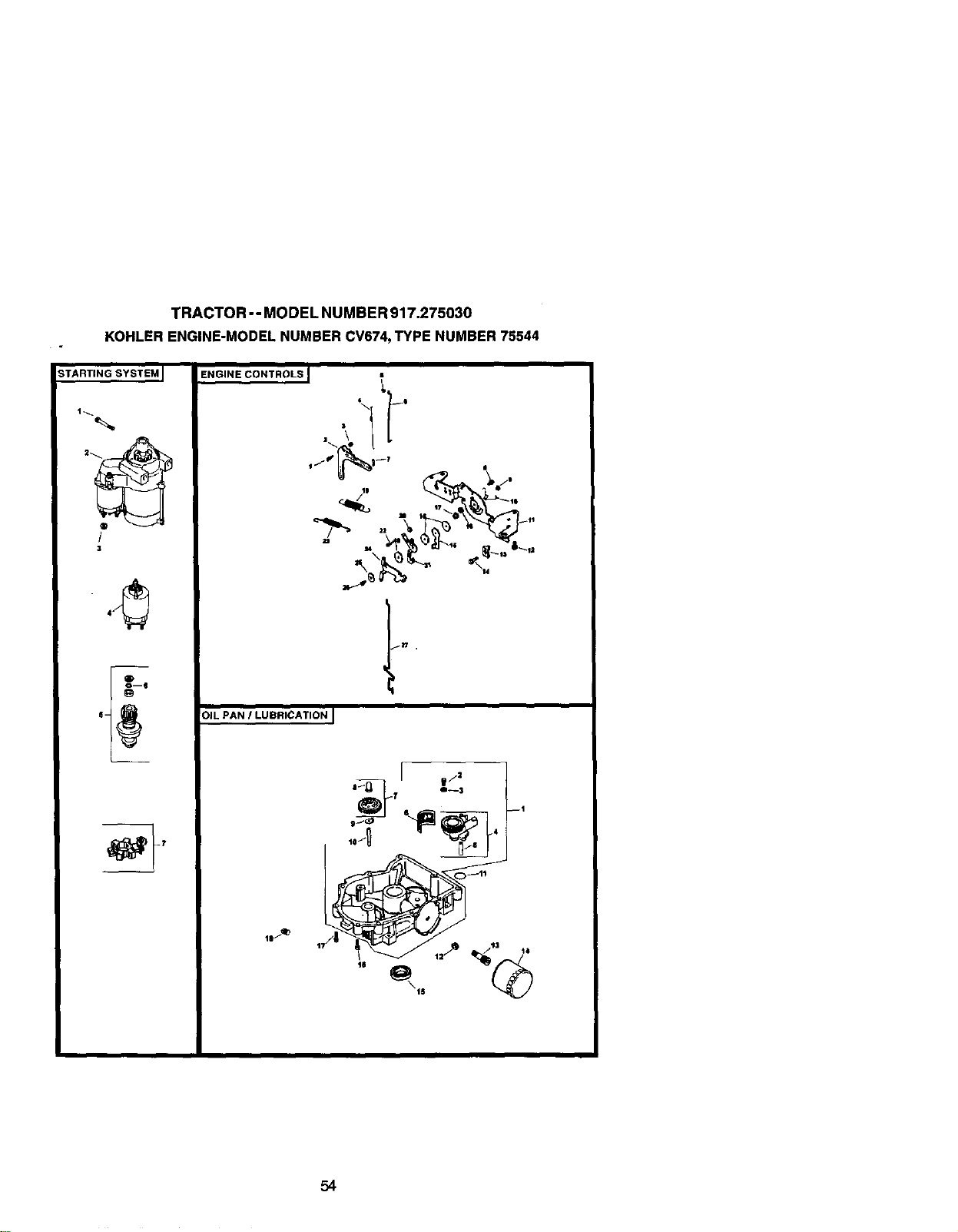
TRACTOR -- MODEL NUMBER 917.275030
KOHLER ENGINE-MODEL NUMBER CV674, TYPE NUMBER 75544
STARTING SYSTEM I
/
3
1_ _ 4 t
C_--1t
54
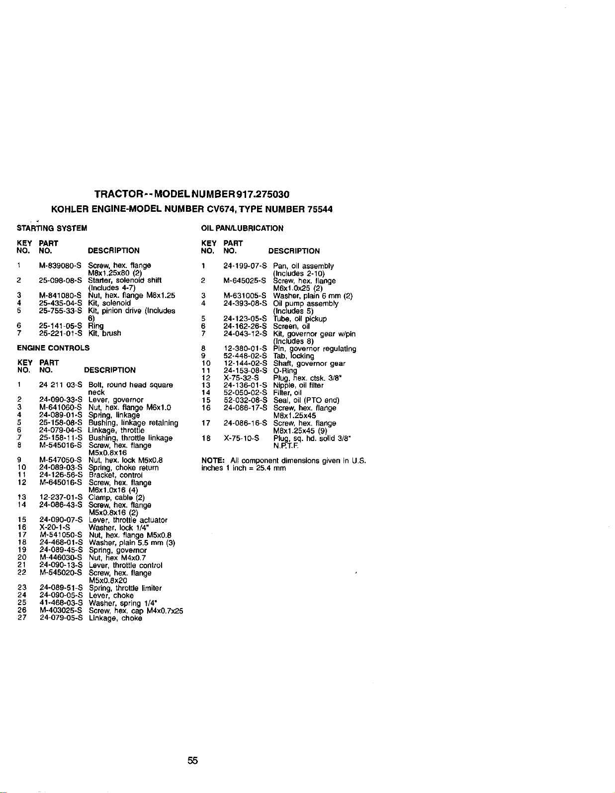
TRACTOR-- MODEL NUMBER 917.275030
KOHLER ENGINE-MODEL NUMBER CV674, TYPE NUMBER 75544
STARTING SYSTEM
OIL PAN/LUBRICATION
KEY PART KEY PART
NO. NO. DESCRIPTION NO. NO. DESCRIPTION
1 M-839080-S Screw hex. flange
M8xf.25x80 2)
2 25-098-08-S Starter, solenod shfl
Includes 4-7)
3 M-841080-S Nut, hex. f ang_ MSxl.25
4 25-435-04-S Kit, solenoid
5 25-755-33-S Kit, pinion drive (Includes
6)
6 25-141-05-S Ring
7 25-221-01-S Kit, brush
ENGINE CONTROLS
KEY PART
NO. NO, DESCR|PTtON
1 24 211 03-S Bolt, round head square
neck
2 24-090-33-S Lever, governor
3 M-641060-S Nut, hex. flange M6xl.0
4 24-089-01-S Spdng, linkage
5 25-158-08oS Bushing, linkage retaining
6 24-079-04oS Linkage, throttle
7 25-158-11-S Bushing, throttle linkage
8 M-545016-S Screw,hex. flange
M5x0.Sx16
9 M-547050-S Nut, hex. lock MSx0.8
10 24-O89-03-S Spring, choke return
11 24-126-56*S Bracket, control
12 M-645016-S Screw, hex. flange
MBxl.0x16 (4)
13 12-237-01-S Clamp, cable (2)
14 24-086-43-S Screw, hex. flange
M5x0.Bx16 (2}
15 24-090-07-S Lever, throttle actuator
16 X-20-1-S Washer, lock 1/4"
17 M-541050-S Nut, hex. flange MSx0.8
18 24-468-01-5 Washer, plain 5.5 mm (3)
19 24-089-45-5 Spring, governor
20 M-44603O-S Nut, hex M4x07
21 24-090-13-S Lever, throttle control
22 M-545020-S Screw, hex. flange
M5x0.Sx20
23 24-089-51-S Spring, throftle timiter
24 24-090-05-S Lever, choke
25 41-468-03-5 Washer, spring 1/4"
26 M-403025-S Screw, hex. cap M4x0.7x25
27 24-079-05-5 Linkage, choke
5
6
7
8
9
10
11
12
13
14
15
16
17
18
24-199-07-S Pan, oil assembly
(includes 2-10}
M.645025-S Screw, hex flange
M6x1.0x25 (2)
M.631005-S Washer, plain 6 mm (2
24-393-08-S Oil pump assembly
(Includes 5)
24-123-05-S Tube, oil pickup
24-162-26-S Screen, oil
24.043-12-S Kit, governor gear w/pin
(includes 8)
12-380-01-S Pin, governor regutatlng
52-448-02-S Tab, locking
12-144-02-S Shaft, governor gear
24-153-O8-S O.Ring
X-78-32-S Plug, hex ctsk. 3/8"
24-136-O1-S Nipple, oil filter
52-050-02-S Filter, oil
52-032-08-S Seal, oil (PTO end)
24-086-17-S Screw, hex. flange
M8x1.25x45
24-086-16-S Screw, hex flange
M8xl.25x45 (9)
X.75-10-5 Plug, sq. hd. solid 3/8"
N.P.J.F
NOTE: All component dimensions given in U.S.
inches 1 ir_ch = 25.4 mm
55
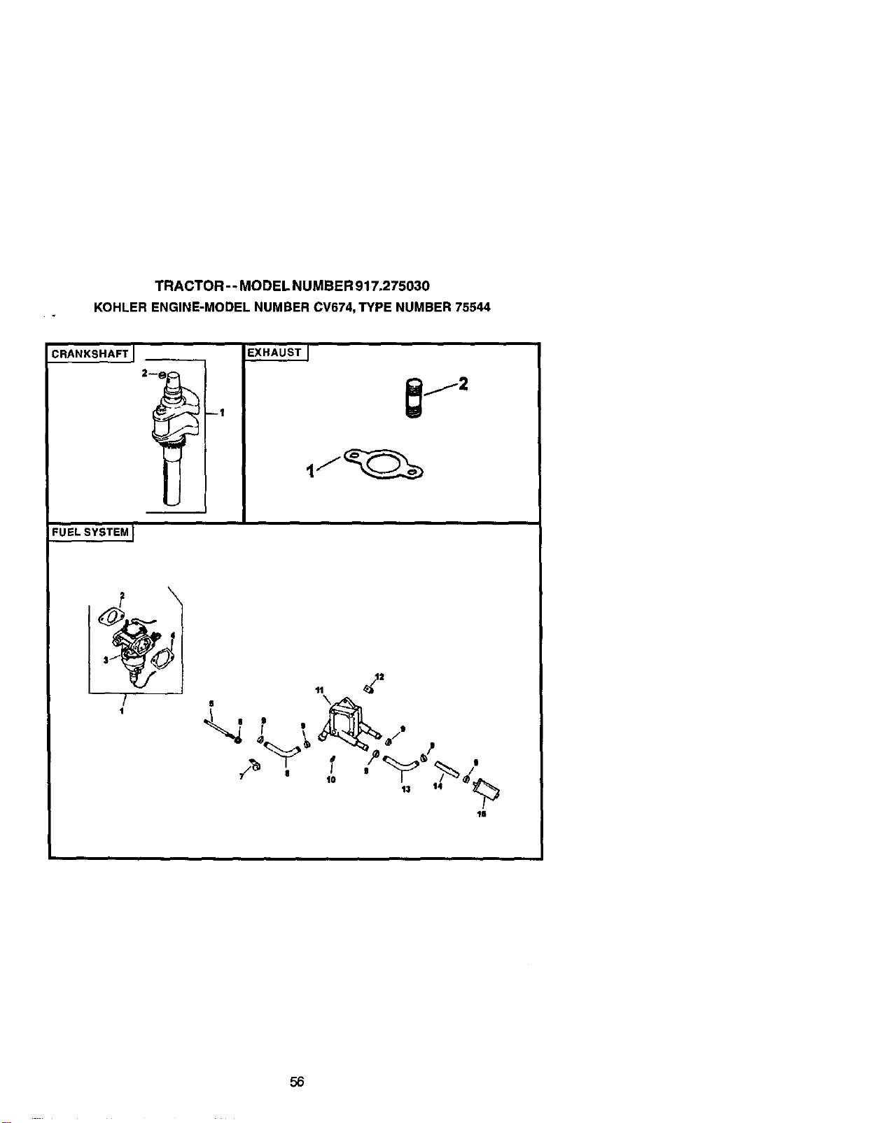
TRACTOR -- MODEL NUMBER 917.275030
KOHLER ENGINE-MODEL NUMBER CV674, TYPE NUMBER 75544
CRANI(SHAFTJ
FUELSYSTEMJ
/
t
EXHAUSTI
6
13 14
"lI
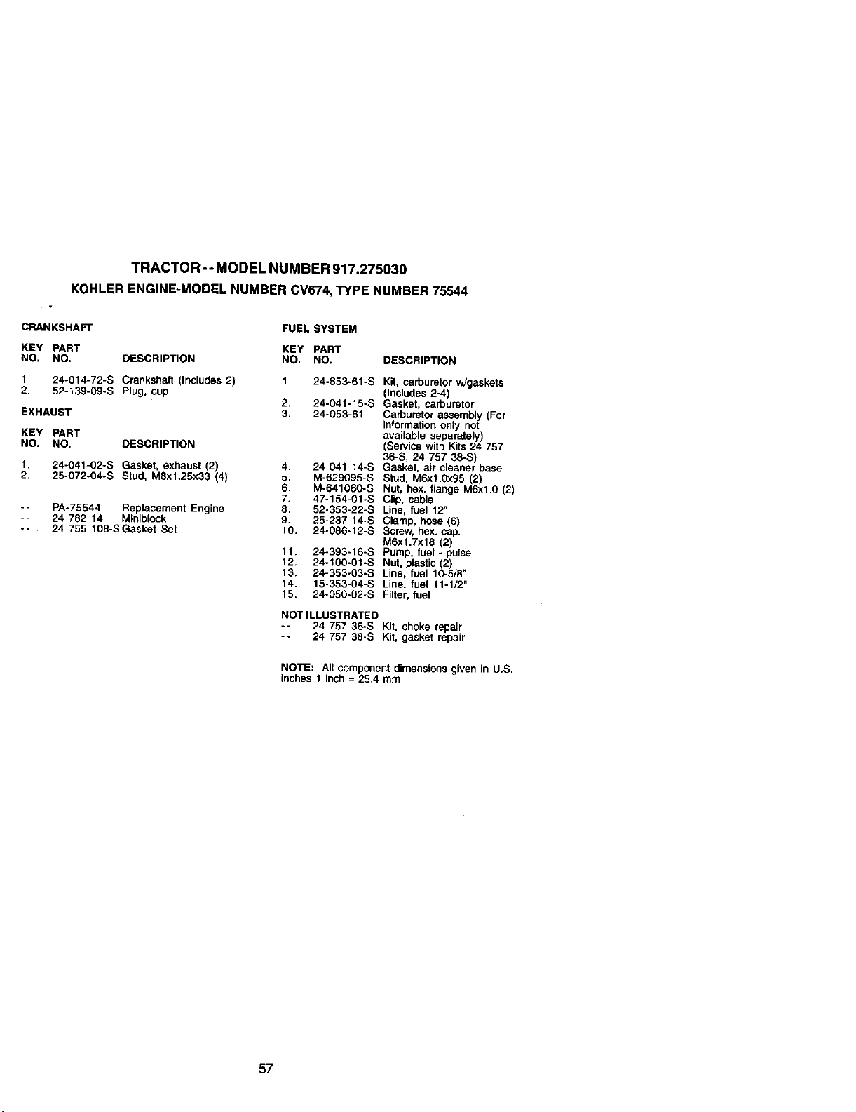
TRACTOR--MODEL NUMBER 917.275030
KOHLER ENGINE-MODEL NUMBER CV674, TYPE NUMBER 75544
CRANKSHAFT
KEY PART
NO. NO. DESCRIPTION
1. 24-014-72-S Crankshaft (Includes 2)
2. 52-139-09-S Plug, cup
EXHAUST
KEY PART
NO. NO. DESCRIPTION
1. 24-041-02-S Gasket, exhaust (2)
2. 25-072-04-S Stud, M8x1.25x33 (4)
-- PA-75544 Replacement Engine
-- 24 782 14 Minibk_ck
-- 24 755 108-SGasket Set
FUEL SYSTEM
KEY PART
NO. NO.
1. 24-853-61 -S
2. 24-041 -15-S
3. 24-053-61
4. 24 041 14-S
5. M-629095-S
6. M-641060-S
7. 47-154-01-S
8, 52-353-22-S
9, 25-237-14-S
10. 24-086-12-S
11. 24-393-16-S
12. 24-100-01-S
13. 24-353-03-S
14. 15-353-04-S
15. 24-050-02-S
DESCRIPTION
K_t, carburetor w/gaskets
_ncludes 2-4)
asket, carburetor
Carburetor assembly (For
information only not
available separately)
(Service with Kits 24 757
36-S, 24 757 38-S)
Gasket, ai_ cleaner base
Stud. M6x1.0x95(2)
Nut, hex. flange M6xl.0 (2)
Clip, cable
Line, fuel 12"
Clamp, hose (6)
Screw hex. cap.
M6xl.7x18 2)
pump, tuel- pulse
Nut, plastic(2)
Line, fuel 10-5/8"
Line, fuet 11-1/2"
Filter, fuel
NOT ILLUSTRATED
-- 24 757 36-S Kit. choke repair
-- 24 757 38-S Kit. gasket repair
NOTE: Aircomponent dimensions given in U.S.
inches 1 inch = 25.4 mm
57

58
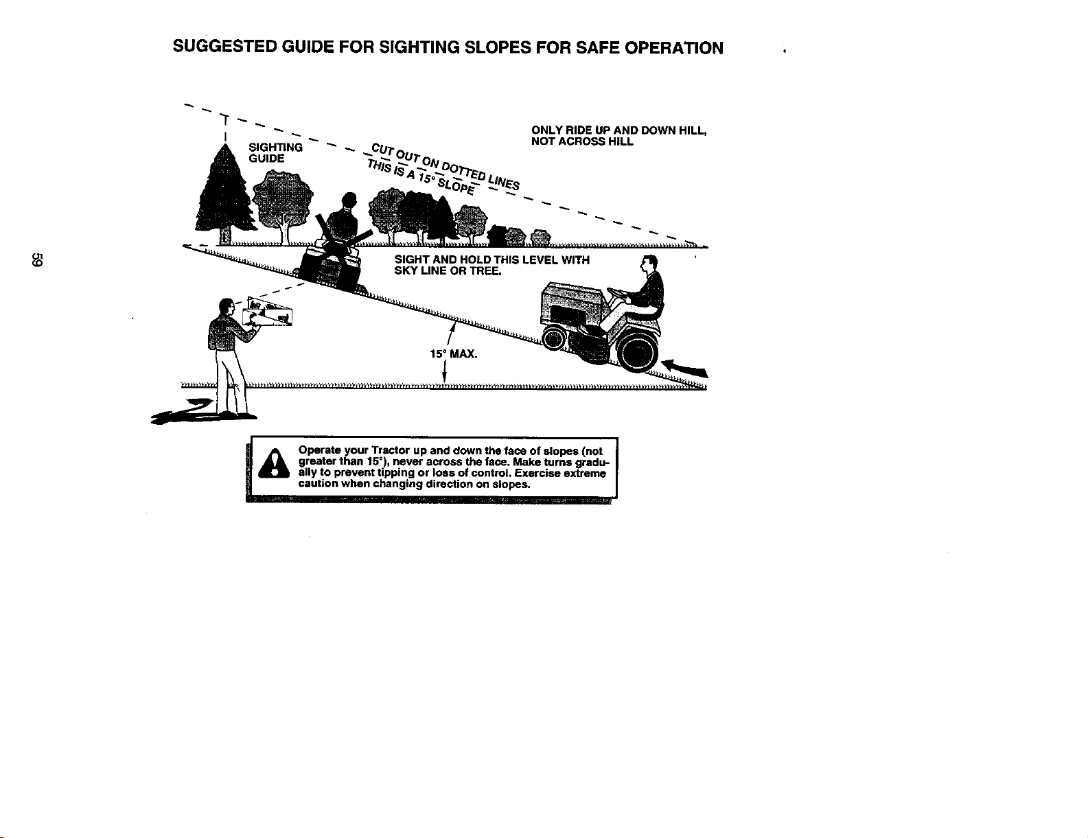
SUGGESTED GUIDE FOR SIGHTING SLOPES FOR SAFE OPERATION
I
SIGHTING _" _. ,,.CUT
GUIDE TH_
ONLY RIDE UP AND DOWN HILL,
NOT ACROSS HELL
f
I
Operate your Tractor up and down the face of slopes (not I
greater than 15°), never across the face. Make turns gradu-
r
any to prevent tipping or loss of control. Exercise extreme
caution when changing direction on slopes.

-Get it fixed, at your home or ours!
For repair of major brand appliances in your own home...
no matter who made it, no matter who sold it!
1-800-4-MY-HOME sMAnytime, day or night
(1-800-469-4663)
www.sears.com
To bring in products such as vacuums,
lawn equipment and electronics for repair, call for
the location of your nearest Sears Parts & Repair Center.
1-800-488-1222 Anytime,dayor night
www.sears.com
For the replacement parts, accessories and owner's manuals
that you need to do-it-yourself, call Sears PartsDirectSi!
1-800-366-PART 6are.-11pr..CST.
(1-800-366-7278) 7 days aweek
www.sears.condpartsdlrect
To purchase or inquire about a Sears Service Agreement:
1-800-827-6655
7 a.m.- 5p.m.CST,Mon.- Sat.
Para pedir serviciode reparacibn a domicilio,
ypara ordenar piezas con entrega a domicilio;
1-888-SU-HOGAR s.
(1-ss8-784-6427)
Au Canada pourserviceen fran_;ais:
1-877-LE-FOYER _
(1-877-533-6937)
© Seam, Roebuck and Co.
177515 1.22.01 RD Printed in U.S.A.


