COMMERCIAL INFORMATION
FOR THE CONSUMER
GB
INSTALLATION,
USE AND
MAINTENANCE
INSTRUCTION
SEM1
-
SEM2
-
SEM5
-
SEM7
-
SEM8
-
SEM10
TECHNICAL
INFORMATION
TYPE: FSED
2
-
The symbol on the
product
or on its
packaging
indicates that this
product
may not
be
treated as
household
waste. lnstead
it
shall be handed aver to the
applicable collection
point far the
recycling
of electrical
an
d e l e c t r o n
i
c
equipment.
By
ensuring
this
product
is
disposed
of
correctly,
you will help prevent
potential
negative consequences far
the
environment
and human health, which could otherwise be caused by
inappropriate
waste
handling
of this
product.
Far more detailed
informati
an about
recycling
of
this
product,
please contact your local city office, your
household
waste di sposai service
or
the shop where you purchased the
product.
This appliance is marked
according
to
the
European directive
2012/19/EC
on waste electrical and
electronic equipment
(
WEEE
)
.
3
GB
Warnings!
The air outlet of the appliance must not be connected to a flue which is used for
exhausting
other fumes from appliances, such as a central heating, boilers
etc..
For the external exhausting of the fumes, comply with the regulations in force.
Ventilate the room suitably according to the laws in force when the appliance is working
to
-
gether with gas, oil or coal burning appliances, at the same
time.
The motor of the peripheral exhausting group is powered by the cooker-hood placed in the
kitchen.
Before connecting the cooker hood to the mains supply, make sure that the voltage indicated in
the rating plate corresponds to the mains voltage in the
home.
Before carrying out any sort of maintenance or cleaning operation, make sure that the appliance
is disconnected from the electrical mains.
An appropriate maintenance ensures a good working and a good performance in the long run.
Useful
warnings:
-
Use an air outlet pipe with a maximum length not higher than 5
meters.
-
Limit the number of bends in the exhausting pipe as every bend reduces the performance up
to one linear meter. (If you use 2 90° bends, than the length of the pipe has not to be higher
than 3
meters).
-
The material for the pipe has to be approved by an authorized company.
-
It is
important
to avoid changes in the diameter (we recommend a diameter of
150mm).
-
Read carefully the manual of instructions and installation of the unit.
-
Sirius will not be responsible for problems of capacity and/ or noise level due to the missed
respect of the warnings included in the manual of instructions.
-
SEM6/7 are equipped with a 200mm diameter hole for the exhausting pipe. If the unit that
has to be connected to the remote fan is already equipped with a 200mm diameter hole, the
nit is recommended to use a pipe with the same diameter in order to get good performances.
Otherwise, if the unit is equipped with a 150mm diameter hole, than it is recommended to
use
the joint (from 200mm to 150mm), already supplied with the unit.
The electric box cable should not be cut or joined together with other cables, since it could
compromise the proper working and the safety conditions of the appliance. Furthermore, this
will invalidate the manufacturer’s warranty
coverage.
Warnings!
The SEM6 suction centrals can be connected to any other
products
from the same manufacturer
if they are equipped with the External Motor version. In case they are connected to products
from other suppliers.
The manufacturer cannot be held responsible for damages caused by a
different
use. No
gua
-
rantee or
indemnity
will be
due.
4
SEM 1 (dis.1)
-
SEM 8
(dis.1a)
Warning! The peripheral exhausting group (remote fitted extraction motor) is built in
class
II (symbol on the rating plate), therefore it must not be
earthed.
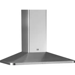
The appliance is designed to exhaust fumes and odours very silently and in the best way. It
must be installed in the house and connected to the cooker-hood, which is in the kitchen
(fig.
2)
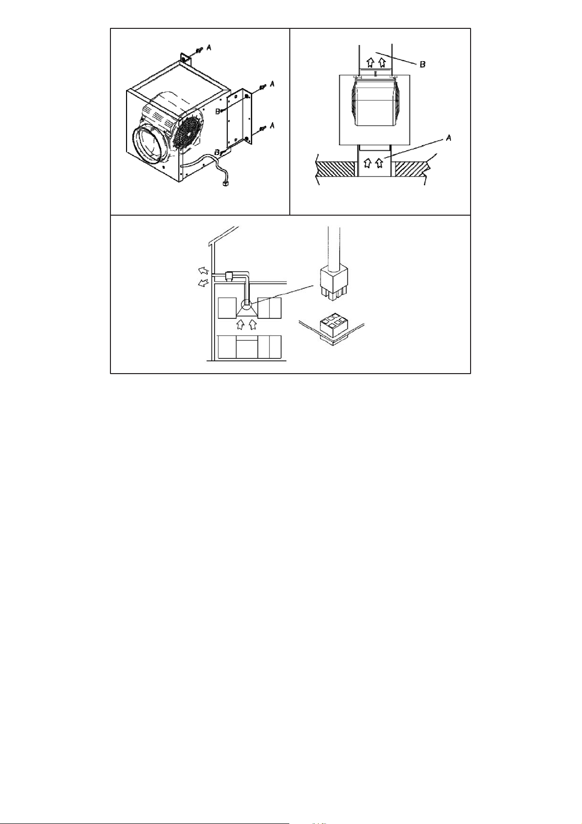
Types of installation: to make the installation easy, the appliance can be fixed on the wall,
on the ceiling or on the floor in a horizontal position (fig. 3 ) or vertically (fig. 4) to the fixing
level.
Note: in the vertical fixing, the brackets supplied can be used only on the longest side (fig.
6
)
.
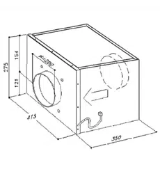
Installation of the appliance: after deciding the position and the type of installation, insert the
anti-vibration rubber caps in the holes of the brackets supplied (fig.
5C).
The rubber caps must be put on the sides which are in contact with the wall.
Put the brackets (fig. 5A) on the remote
fitted
extraction motor by matching its holes with those
of the brackets. Fix with the screws supplied (fig.
5B).
Put the group on the point
previously
chosen for the
installation
and mark the points on the wall
where the holes must be drilled.
Insert the dowels supplied in the holes (fig. 6A). Put the remote fitted extraction motor on the
wall by matching the holes of the brackets with the plastic dowels. Screw with the screws
sup
-
plied (fig.
6B).
Connection of the pipes: the appliance is endowed with an entrance and an outlet to connect
the pipes. Before connecting the exhaust pipes, check the direction of the air showed on the
external label (fig. 7). Connect the pipes and fix them with appropriate metal clamps
(exhaust
pipes and metal clamps have to be supplied by the installer). The pipe (fig. 7A) must be con
-
nected with the cooker-hood placed in the kitchen, and the pipe (fig. 7B) must be directed
outside the building.
Electrical connection of the hood SEM 1: the appliance is equipped with a 7m electrical
ca
-
ble with a six- pin connection at one end. Insert it into the hood’s connection (External Motor
version)
Electrical connection to the hood SEM 8: the unit is supplied with a pipe 7 meters long. After
having let the cable pass through the plastic pipe (fig. 12E) placed in the wall (fig. 12D), placed
it closed to the unit and connect the 6 poles connector (fig. 12E) and the 2 poles connector
(fig.
12G).

5
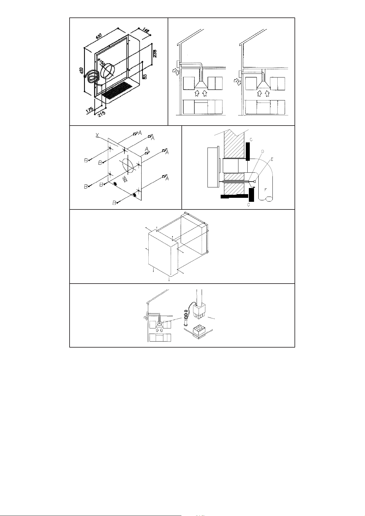
SEM 2
(fig.9)
Warning! The remote fitted exhausting group (external motor) is built in class I plate,
the
-
refore it needs the earth connection.
The appliance was designed to exhaust odours and vapours in the best way. The appliance is
to be installed on the outside wall of the house and connetted to the cooker-hood which is in
the kitchen (fig.
10)
Installation: the mounting of the appliance is to be made by qualified technicians. Using the
appropriate drilling jig (fig. 11) drill all the holes marked on it into the external wall, by paying
attention not to damage water pipes or power
lines.
The holes on the wall are to be drilled with a 8 mm. bit. Insert, step by step, the
following
parts in the holes drilled:
-
the corresponding plastic dowels supplied (fig. 11A)
-
the two telescopic pipes in the hole of 160
mm.
-
the plastic pipe of 40 mm. diameter.
Before leaning the appliance against the wall, insert the supply cord in the plastic pipe. Fix the
appliance without the stainless steel external body, which was previously removed from the
motor block, by matching the holes of the motor block with the holes on the wall. Tighten with
the screws supplied
(fig.11B).
Connection of the pipes: the appliance is endowed with an air entrance to be connected with
the telescopic pipes and an air outlet.
After
fixing the appliance on the external wall, connect the two telescopic pipes, which are
pla
-
ced inside the wall, with the cooker-hood through the flexible pipes (fig.
12).
The fixing between the pipes have to be made with
appropriate
metal clamps (pipes and clamps
are supplied by the installer).
Electrical connection to the
hood:
the unit is supplied
with
a pipe 7 meters long.
After
having let the cable pass through the plastic
pipe (fig. 12E) placed in the wall (fig. 12D), placed it closed to the unit and connect the 6 poles
connector (Fig. 12E) and the 2 poles connector (Fig.
12G).
In order to avoid water infiltrations, please apply silicone on the product perimeter, close to
the wall.
Installation of the stainless steel external body: put the stainless steel body again, by
ma
-
tching the air exhausting grid with the air outlet of the motor block (fig.
13).
6
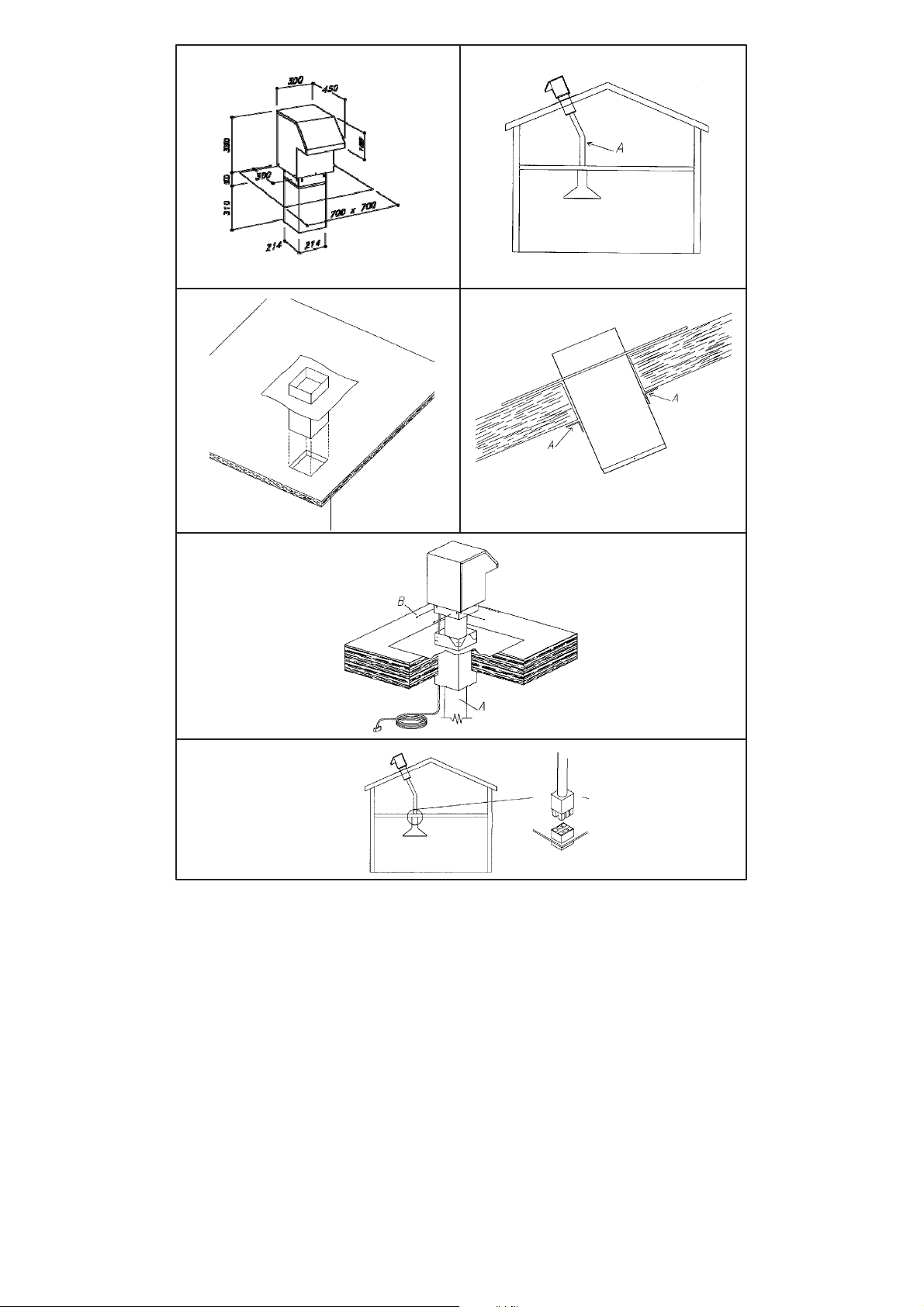
SEM 5
(fig.21)
Warning! The remote fitted exhausting group (external motor) is built in class II
(see
symbol on the rating plate), therefore it must not be
earthed.
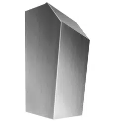
This model has been
specifically
studied to suction vapours and odours without noise.It should
be installed outside and connected to the hood in the kitchen (fig.
22).
Roof installation: make a 22 x 22 cm square opening on the roof, and then insert the lower part
of the remote fitted exhausting motor (fig.
23).
Put the two brackets as shown in fig 24A and mark the holes you are going to
drill
on the lower
part of the remote fitted exhausting motor.
Make all the holes, and then fasten securely.
Insert the pipe connecting the hood outlet line with the upper part of the remote fitted
extrac
-
tion motor (fig.25A); the pipe should pass into the lower part of the remote fitted
exhausting
motor (fig.
25).
Fix the pipe to the upper part of the remote fitted exhausting motor with a metal hose clamp.
Assembly
the upper and the lower part of the remote
fitted
exhausting motor using the 8 screws
provided
(fig.25B).
Electrical connection of the hood: the appliance is equipped with a 7m electrical cable.
Con
-
nect it to the six-pin connection of the appliance in the kitchen.

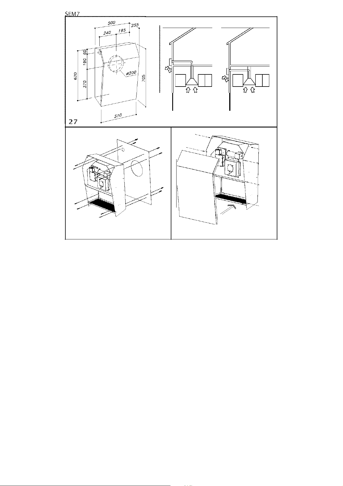
7
SEM 7 (dis.
27)
Warning!
The remote fitted exhausting group (external motor) is built in class I plate, therefore it
needs
the earth connection.
The appliance was designed to exhaust odors and vapors in the best way. The appliance is to
be installed on the outside wall of the house and connected to the cooker-hood which is in the
kitchen (fig.
28)
Installation:
the mounting of the appliance is to be made by qualified technicians. Using the appropriate
drilling
jig (fig. 29)
drill
all the holes marked on it into the external wall, by paying attention not
to damage water pipes or power lines. The holes on the wall are to be drilled with a 8 mm.
bit.
Insert, step by step, the following parts in the holes drilled:
-
the corresponding plastic dowels supplied (fig.
29)
-
the two telescopic pipes in the hole of 200
mm.
-
the plastic pipe of 40 mm. diameter.
Before leaning the appliance against the wall, please remove the stainless steel carter using the
8 perimetrical screws (fig. 30), then insert the supply cord in the plastic pipe. Fix the appliance
without the stainless steel external body, which was
previously
removed from the motor
block,
by matching the holes of the motor block with the holes on the wall. Tighten with the screws
supplied.
Connection of the
pipes:
the appliance is endowed with an air entrance to be connected with the telescopic pipes and an
air outlet. After fixing the appliance on the external wall, connect the two telescopic pipes
(fig.
12C), which are placed inside the wall, with the cooker-hood through the flexible
pipes.
The fixing operations have to be carried out by using suitable metallic tools (pipes and tools
have to be supplied by the installers).
Electrical connection to the
hood:
the unit is supplied
with
a pipe 7 meters long.
After
having let the cable pass through the plastic
pipe (fig. 12E) placed in the wall (fig. 12D), placed it closed to the unit and connect the 6 poles
connector (Fig. 12E) and the 2 poles connector (Fig.
12G).
In order to avoid water infiltrations, please apply silicone on the product perimeter, close to
the wall.
Installation of the external carter:
mount the aesthetic carter making sure that the grill will match with the block motor air outlet
(dis.
30).

8
SEM10 (fig.
31)
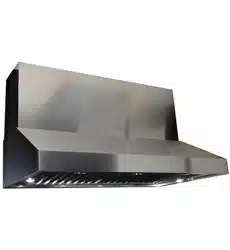
SEM10 product has been designed to be installed under the kitchen cabinet, corresponding to
the downdraft lower air outlet . This product can work only if it is used in combination with
a
downdraft
equipped with external motor,
manufactured
by the same producer.
The appliance has been designed to suck vapours and odours in an optimal and almost
noi
-
seless way . We recommend to use the product only in
FILTERING
MODE and to use a constant
diameter piping of 150mm or similar
sections.
We recommend to use piping without elbows, as they negatively affect the performance of the
appliance.
Installation
procedure: place the appliance under the
downdraft
, corresponding to the air
out
-
let, as shown in (fig.
32).
All fittings are supplied with the appliance, along with a rectangular pipe that connects the
downdraft
to the SEM10 product
The appliance air outlet shall be connected to the cabinet, in such a way that the air sucked in
the kitchen can be recirculated back into the room. Piping to be connected to the SEM10
pro
-
duct air outlet are not supplied with the appliance.
It is possible to direct the product air outlet according to your installation requirements, by
rotating the air outlet flange as shown in (fig.
33).
9
o
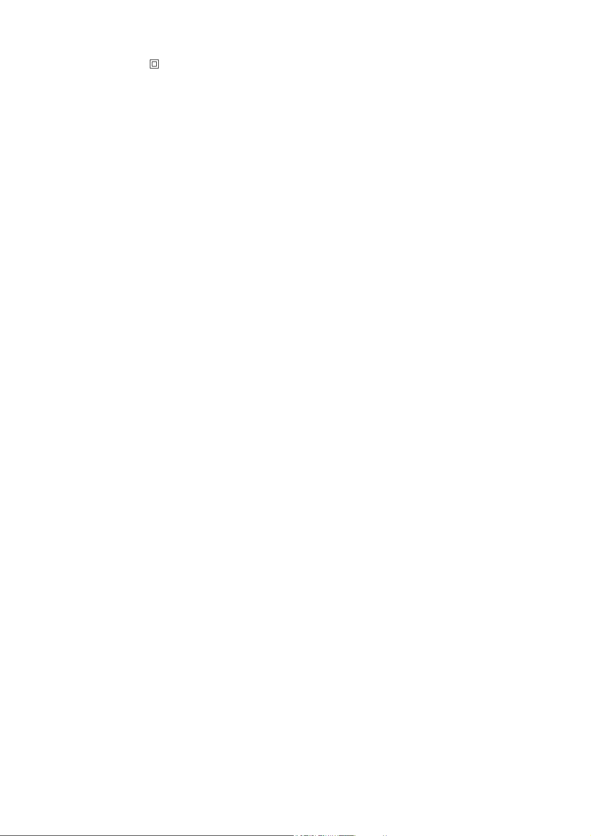
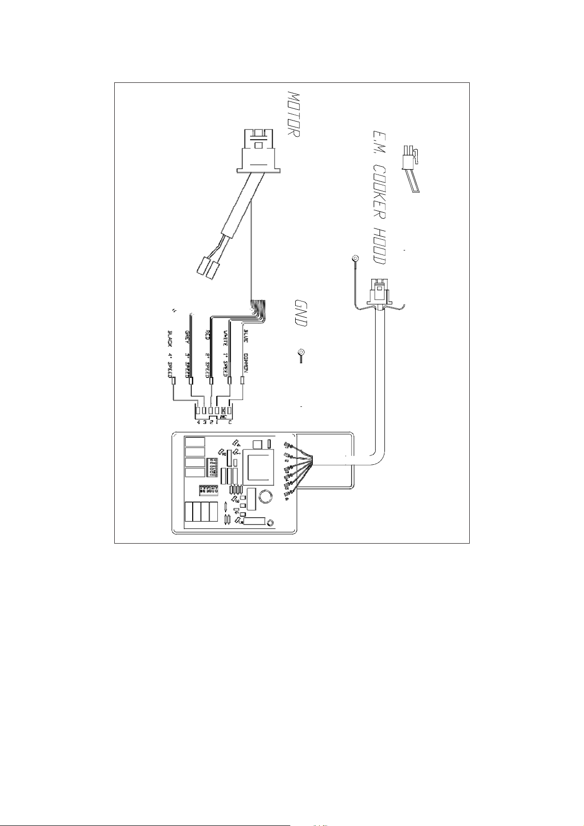
WIRINC DIACRAM SEMI
-
SEMS
Hotor type' GS50
MJHINAL PllfiER
'
300
Il
AHPE:Rt
(f)
'
HAX J.i!OA
INSULAT!llN CLASS'
B
PRllTE:CT!llN CLASS'
II
7
m
et:
2
o
L
z
U
z
o
o
CJ
j
Q
x
(
/J
10
.D
=D
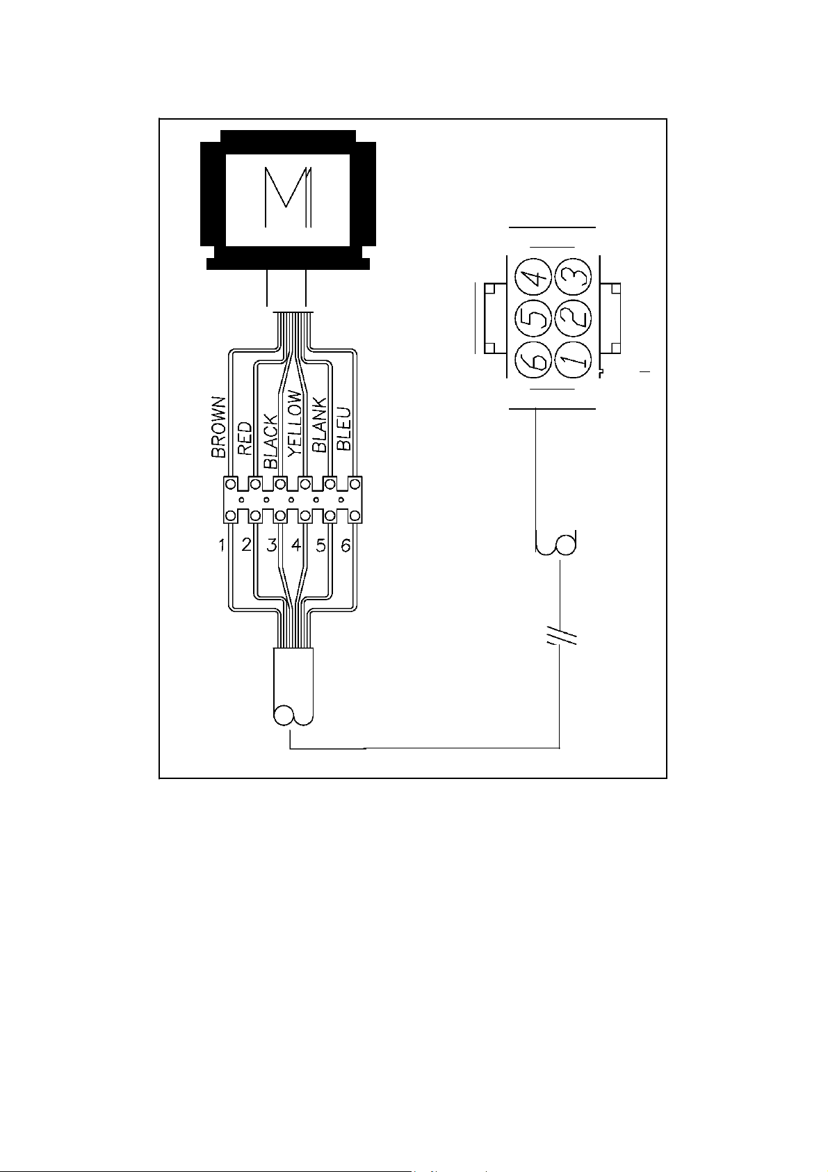
WIRING DIAGRAM
SEM2
'
5
"
•
D
4-,Da.
JJ
am
0
D
=
ITII
J
oo
o
c::::::J
©
=

11
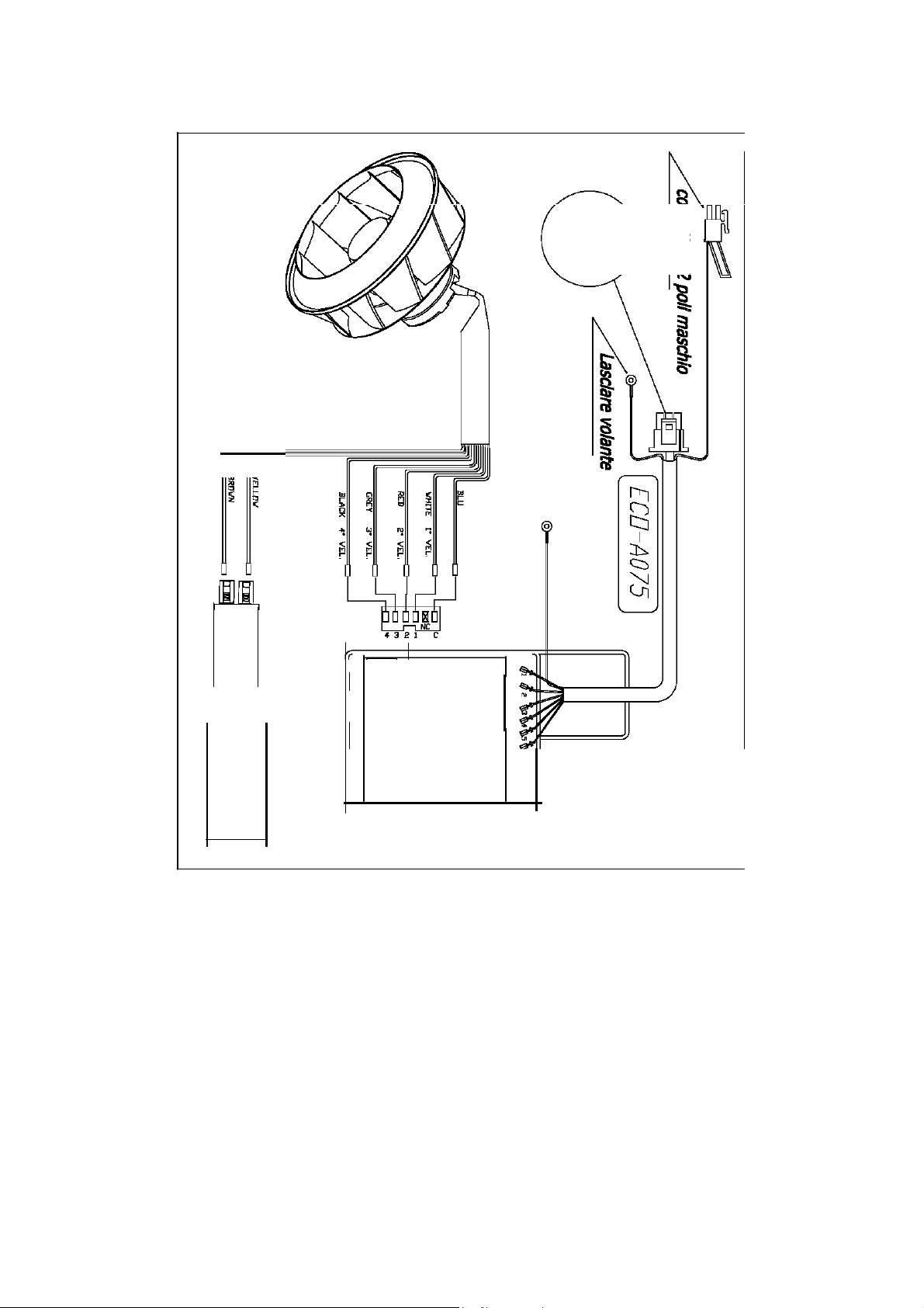
WIRINC DIACRAM
SEM7
8
o
Q
@
Q
c
(3
==tJ
©oD
12
[
j
WIRINC DIACRAM SEM8
'8
iii
CII
/D
iii
::::.
::::.
o
a
13
CAPACITO
R
WIRING DIAGRAM
SEM10

14
SEM1
1
1a
2
3
4
5
15
6
7
8
16
SEM2
9
10
11
12
13
14
17
SEM5
21
22
23
24
25
26
18
l
Mll
28
l
Mll
29
30

19
SEMlO
j
i
31
32
33

90004200486
GM
06/::_6