Loading ...
Loading ...
Loading ...

• 5 •
7. FOLLOW THESE STEPS WHEN BATTERY IS OUTSIDE VEHICLE
WARNING: A SPARK NEAR THE
BATTERY MAY CAUSE A BATTERY
EXPLOSION. TO REDUCE THE RISK OF
A SPARK NEAR THE BATTERY:
7.1 Check polarity of battery posts. POSITIVE
(POS, P, +) battery post usually has a larger
diameter than NEGATIVE (NEG, N, –) post.
7.2 Attach at least a 24-inch-long 6-gauge
(AWG) insulated battery cable to
NEGATIVE (NEG, N, –) battery post.
7.3 Connect POSITIVE (RED) charger clip to
POSITIVE (POS, P, +) post of battery.
7.4 Position yourself and free end of cable as
far away from battery as possible – then
connect NEGATIVE (BLACK) charger clip
to free end of cable.
7.5 Do not face battery when making nal
connection.
7.6 When disconnecting charger, always do
so in reverse sequence of connecting
procedure and break rst connection
while as far away from battery as
practical.
7.7 A marine (boat) battery must be removed
and charged on shore. To charge it on
board requires equipment specially
designed for marine use.
8. GROUNDING AND AC POWER CORD CONNECTIONS
8.1 This battery charger is for use on a
nominal 120 volt circuit. The charger
must be grounded, to reduce the risk of
electric shock. The plug must be plugged
into an outlet that is properly installed
and grounded in accordance with all local
codes and ordinances. The plug pins
must t the receptacle (outlet). Do not use
with an ungrounded system.
8.2 DANGER: Never alter the AC cord or
plug provided – if it does not t the outlet,
have a proper grounded outlet installed
by a qualied electrician. An improper
connection can result in a risk of an
electric shock or electrocution.
NOTE: Pursuant to Canadian
Regulations, use of an adapter plug
is not allowed in Canada. Use of an
adapter plug in the United States is not
recommended and should not be used.
8.3 USING AN EXTENSION CORD
The use of an extension cord is not
recommended. If you must use an
extension cord, follow these guidelines:
• Pins on plug of extension cord must be
the same number, size, and shape as
those of plug on charger.
• Ensure that the extension cord is
properly wired and in good electrical
condition.
• Wire size must be large enough for
the AC ampere rating of charger, as
specied:
Length of cord (feet) 25 50 100 150
AWG* size of cord 18 16 14 12
*AWG-American Wire Gauge
9. ASSEMBLY INSTRUCTIONS
9.1 Remove all cord wraps and uncoil the cables prior to using the battery charger.
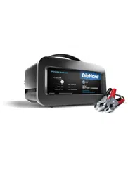
10. CONTROL PANEL
LED INDICATORS
CLAMPS REVERSED (red) LED
ashing: The connections are reversed.
CHARGING (yellow/orange) LED lit:
The charger is charging the battery.
CHARGING (yellow/orange) LED
ashing: The charger is in abort mode.
CHARGED/MAINTAINING (green) LED
pulsing: The battery is fully charged and
the charger is in maintain mode.
NOTE: See the Operating Instructions
section for a complete description of the
charger modes.
RATE SELECTION
Use this button to set one of the following
selections:
• 6A<>2A CHARGE/MAINTAIN – For
charging small and large batteries. Not
recommended for industrial applications.
• 10A BOOST – For quickly adding
energy to a severely discharged or large
capacity battery prior to ENGINE START.
The unit will automatically switch to
6A<>2A CHARGE/MAINTAIN after the
10A BOOST operation has completed.
• 50A ENGINE START – Provides
additional amps for cranking an engine
with a weak or run-down battery. Always
use in combination with a battery.
Loading ...
Loading ...
Loading ...