Loading ...
Loading ...
Loading ...
19
OPERATIONS MANUAL
REFRIGERATED BASES & PIZZA PREP TABLES
MOUNTING CASTER SUPPORT PLATES
If the standard stem casters on a cabinet are not properly main-
tained and tightened, or if the unit is excessively overloaded and
moved around, the threaded inserts in the bottom of the cabinet
can become stripped, twisted or collapsed. If this occurs and
the stem casters cannot be mounted securely, rigid caster sup-
port plates can be fitted to provide the strength needed to safely
use your cabinet. Each caster support plate assembly is made
of heavy gauge galvanized steel, with (2) casters attached for
maximum rigidity. The plate has holes that allow you to fasten
the plate assembly to the bottom of the cabinet with sheet metal
screws and bolts. Contact the factory to obtain the correct parts
for your model.
IMPORTANT NOTE: Always wear proper work gloves and
use appropriate safety equipment. You may CAREFULLY
lay the cabinet on it’s back, but only FOR A BRIEF PERIOD
OF TIME. Caution must be taken to ensure you DO NOT
DAMAGE the louvered back panel, refrigeration system
components, or copper tubing located behind the panel.
The cabinet must be properly blocked, to allow room to
get your hands in to lift without damaging the cabinet or
crushing the vents on the back panel. DO NOT PLUG-IN
OR OPERATE THE REFRIGERATION SYSTEM FOR AT
LEAST THREE (3) HOURS AFTER RETURNING THE UNIT
TO AN UPRIGHT POSITION, AS THIS CAN DAMAGE THE
COMPRESSOR.
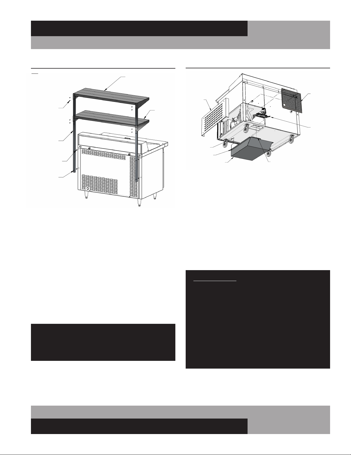
INSTALLING FRONT BREATHER KIT
Disconnect cabinet power by unplugging cord from electrical
supply. Remove back and/or side panel to gain access to the
machine compartment (see Figure 15). Loosen (2) screws
on bottom of cabinet, towards front of machine compartment.
Position discharge duct under cabinet as shown and insert tab
into back edge of cutout on bottom of cabinet. Lift front of the
duct, so keyhole goes over screws in cabinet and duct is flat
against bottom of cabinet. Slide duct towards back of cabinet
and tighten screws. Position fan assembly as shown and place
into notch at rear of compressor compartment base. Secure with
(2) screws provided. Plug fan power cord into a standard 115
volt wall outlet or into the receptacle in the cabinet control box
labeled “vaporizer”, located at the front of the machine compart-
ment. Reconnect power to the cabinet.
ANY RESTRICTIONS TO THE AIR FLOW THROUGH THE
FRONT GRILL OR UNDER THE CABINET CAN DAMAGE
THE REFRIGERATION SYSTEM AND WILL VOID ALL
WARRANTIES.
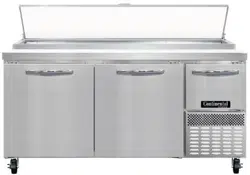
10-32 SCREWS
UPRIGHT
1/4-20 SCREWS
KEYHOLES
OPPOSITE
THESE HOLES
TOP SHELF
BOTTOM
SHELF
(NO NOTCHES IN BACK CORNERS)
FIGURE 14: Overshelf Installation
FIGURE 15: Front Breather Kit
DISCHARGE DUCT
FAN
ASSEMBLY
REAR
ACCESS
PANEL
SIDE
PANEL
TAB
KEYHOLE
SCREW
Note: Overshelf installation is the same for both SW
models (shown below) and CPA/CRA models
Loading ...
Loading ...
Loading ...