Loading ...
Loading ...
Loading ...
page 7
WARNING: Turn off circuit breakers to current fixture from
breaker panel and be sure switch is turned to the OFF
position.
CAUTION: Be sure outlet box is properly grounded and
that a ground wire (GREEN or Bare) is present.
Make sure all electrical connections comply with Local
Codes or Ordinances and the National Electrical Code. If
you are unfamiliar with electrical wiring or if the
house/building wires are different colors than those
referred to in the diagram to the right, please use a
qualified electrician.
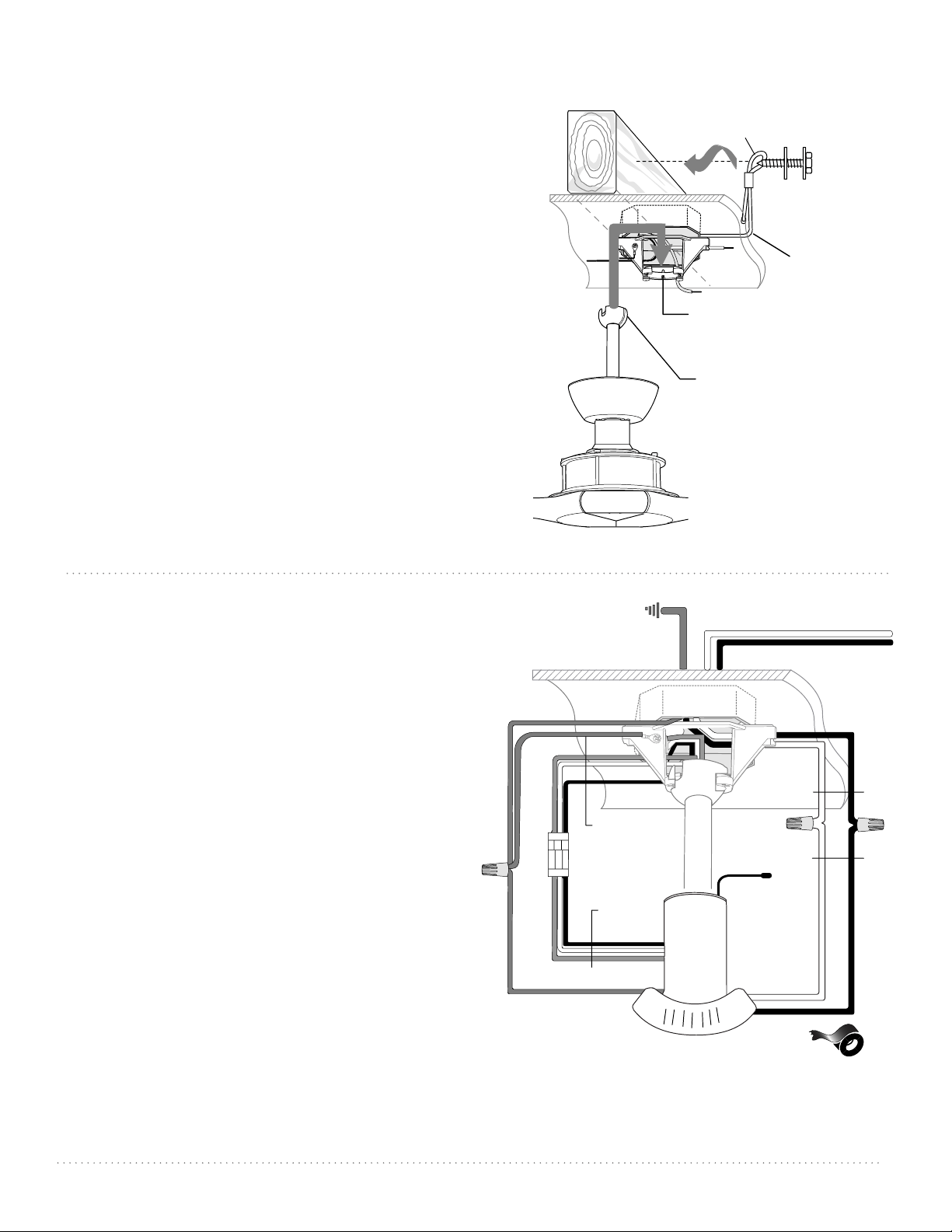
When downrod is secured in place on the hanging
bracket, wire the receiver as follows:
Connect 3-wire plug from fan to 3-wire plug from remote
control receiver. Make sure plugs snap together
completely.
Connect BLACK wire from remote control receiver to
BLACK wire from ceiling with wire connector provided.
Connect WHITE wire from remote control receiver to
WHITE wire from ceiling with wire connector provided.
Connect all GREEN wires together to BARE/GREEN
wire from ceiling with wire connector provided.
Gently insert receiver (flat side down) into hanging
bracket and carefully push taped wire connectors into
outlet box. Let antenna rest outside of hanging bracket.
["Wiring" continued on next page.]
7. Wiring.
6. Fan Assembly. (cont.)
With the hanging bracket secured to the outlet box and
able to support the fan, you are now ready to hang your
fan. Grab the fan firmly with two hands. Slide downrod
through opening in hanging bracket and let hanging ball
rest on the hanging bracket. Turn the hanging ball slot until
it lines up with the hanging bracket tab.
WARNING: Failure to align slot in hanging ball with tab in
hanging bracket may result in serious injury or death.
Tip: Seek the help of another person to hold the
stepladder in place and to help lift the fan up to you once
you are set on the ladder.
Find a secure attachment point (wood ceiling joist highly
recommended) and secure safety cable. It will be necessary
to use a heavy duty wood screw, washer and lock washer
(not supplied) with the safety cable loop. If necessary,
adjust the loop at the end of the safety cable. The loop at
the end of the safety cable should just fit over the threads
on the wood screw. Test safety cable by pulling on loose end
with pliers. If the safety cable slips, the loop must be adjusted
tighter. Extra cable slack can be left in ceiling area.
diagram 6
motor housing
safety cable
safety cable loop
wood
ceiling
joist
wood screw
and washer
hanging bracket tab
hanging ball slot
ground (green
or bare)
white supply wire
black supply wire
from receiver
black
AC IN L
AC IN N
white
white
ground (green or bare)
ground (green)
antenna
from ceiling
receiver
black
*
(wiring for receiver)
3-wire plug
from
receiver
from fan
* Wrap each wire connector separately with
electrical tape as an extra safety measure.
Loading ...
Loading ...
Loading ...