Loading ...
Loading ...
Loading ...
18
PIPING INSTALLATION
Indoor Condensate Drain Piping
Observe all local sanitary codes when installing condensate drains.
WARNING
The drain piping should be as short as possible with a constant downward slope. It is recommended
to install the condensate drain system with hard polyvinyl chloride (PVC) pipe and matching
connectors. Use piping of the same or greater diameter as the unit connection.
The Floor/Ceiling drainage port diameter is 11/16-in
(17-mm) OD.
Pitch the condensate drain pipe at a gradual 2.5% pitch
(Example: ¼-in drop over a 10-in length) without
obstructions. Use pipe hanger/brackets to support
the condensate drain pipe from dropping.
If a gradual pitch from the drainage port is not obtainable, use an auxiliary condensate pump with
float valve. A float valve is recommended to shut off the system if auxiliary pump fails.
NOTE: Insulate condensate hose and/or pipes to prevent sweating which may cause
water stains or wall damage.
Ceiling
Hangers
Wall
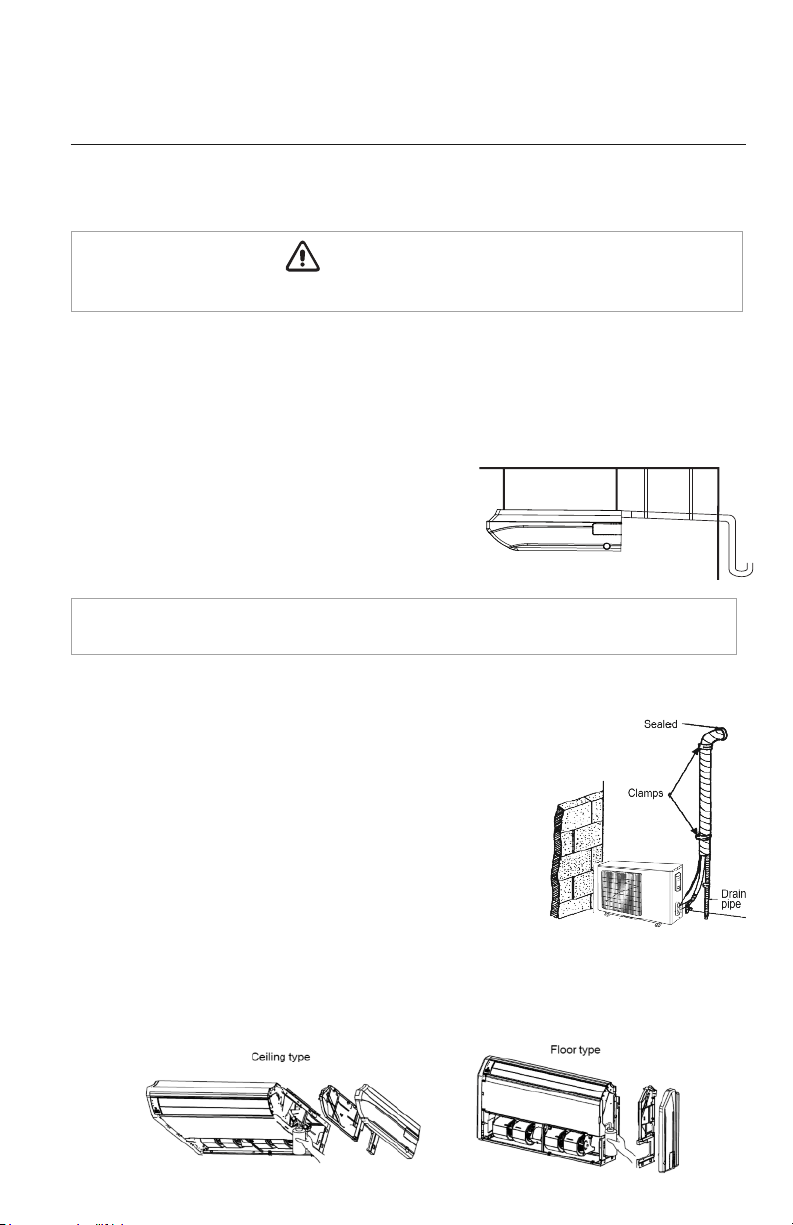
Completing Condensate Drainage Piping
• Include the exterior section of condensate hose in the pipe/wire bundle.
• Fasten the refrigerant and condensate pipe assembly to the exterior
wall for support.
• The drain pipe should terminate 6 inches above grade.
Test the Condensate Drainage Piping
• Find the drainage port with the air inlet grille and right side panel removed.
• Slowly add 20 to 24 oz. of water to the drain pan as shown below.
• Water must drain freely from the unit If not, check the pipe slope or see if there are any pipe restrictions.
• Verify all piping joints are leak free.
Typical Drainage System
Loading ...
Loading ...
Loading ...