
Owner's Manual
ELECTRIC START
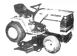
42" MOWER
AUTOMATIC
LAWN TRACTOR
Model No.
917.272420
• Safety
• Assembly
• Operation
• Maintenance
• Repair Parts
_ This product has a low emission engine which operates
differently from previously built engines. Before you start the
engine, read and understand this Owner's Manual,
CAUTION:
Read and follow all Safety
Rules and Instructions before
operating this equipment.
For answers toyour questions
about this product, Call:
1-800-659-5917
Sear• Craft•man Help Line
5 am - 5 pm, Mon- Sat
Sears, Roebuck and Co., Hoffman Estates, I160179
Visit our Craftsman website:www.sears.com/craftsman
Warranty...............................................2
SafetyRules.........................................3
ProductSpecifications..........................6
Assembly..............................................8
Operation............................................11
Maintenance.......................................18
Maintenance Schedule ...................... 18
Service and Adjustments .................... 23
Storage ............................................... 29
Troubleshooting ................................. 30
Repair Parts ........................................ 34
Parts Ordering ..................... Back Cover
LIMITED TWO YEAR WARRANTY ON CRAFTSMAN RIDING EQUIPMENT PARTS
For two (2) years from the date of purchase, if this Craftsman Riding Equipment is
maintained, lubricated and tuned up according to the instructions in the owner's
manual, Sears will repair or replace, free of charge, any parts found to be defective in
material or workmanship. Warranty service is available free of charge by returning
your Craftsman riding equipment to your nearest Sears Service Center. In-home
warranty service is available but a trip charge will apply. This warranty applies only
while this product is in the United States.
This Warranty does not cover:
• Expendable items which become worn during normal use, such as blades, spark
plugs, air cleaners, belts and oil filters.
• Tire replacement or repair caused by punctures from outside objects, such as nails,
thorns, stumps, or glass.
• Repairs necessary because of operator abuse, including but not limited to, damage
caused by towing objects beyond the capability of the dding equipment, impacting
objects that bend the frame or crankshaft, or over speeding the engine.
• Repairs necessary because of operator negligence, including but not limited to,
electrical and mechanical damage caused by improper storage, failure to use the
proper grade and amount of engine oil, failure to keep the deck clear of flammable
debris, or the failure to maintain the equipment according to the instructions
contained in the owner's manual.
• Engine (fuel system) cleaning or repairs caused by fuel determined to be contami-
nated or oxidized (stale). In general, fuel should be used within thirty (30) days of its
purchase date.
• Riding equipment used for commercial or rental purposes. A product is "used for
commercial purpose" if is used for any purpose other than single family household
dwellings or in usage where profit is made.
LIMITED 90 DAY WARRANTY ON BATTERY
For ninety (90) days from date of purchase, if any battery included with this riding
equipment proves defective in material or workmanship and our testing determines
the battery will not hold a charge, Sears will replace the battery at no charge. War-
ranty service is available free of charge by returning your Craftsman riding equipment
to your nearest Sears Service Center. In-home warranty service is available but a trip
charge will apply. This warranty applies only while this product is in the United States.
TO LOCATE THE NEAREST SEARS SERVICE CENTER OR TO SCHEDULE IN-
HOME WARRANTY SERVICE, SIMPLY CONTACT SEARS AT 1-800-4-MY-HOME
This Warranty gives you specific legal rights, and you may also have other rights
which may vary from state to state.
Sears, Roebuck and Co., D/817 WA, Hoffman Estates, IL 60179
2
IMPORTANT: This cutting machine is capable of amputating hands and feet and
throwing objects. Failure to observe the following safety instructions could result in
serious injury or death.
I. GENERAL OPERATION
• Read, undemtand, and follow all
instructions in the manual and on the
machine before starling.
• Only allow responsible adults, who are
familiar with the instructions, to operate
the machine.
• Clear the area of objects such as
rocks, toys, wire, etc., which could be
picked up and thrown by the blade.
• Be sure the area is clear of other
people before mowing. Stop machine
if anyone enters the area.
• Never carry passengers.
• Do not mow in reverse unless abso-
lutely necessary. Always look down
and behind before and while backing.
• Be aware of the mower discharge
direction and do not point it at anyone.
Do not operate the mower without
either the entire grass catcher or the
guard in place.
• Slow down before turning.
• Never leave a running machine
unattended. Always turn off blades, set
parking brake, stop engine, and
remove keys before dismounting.
• Turn off blades when not mowing.
• Stop engine before removing grass
catcher or unclogging chute.
• Mow only in daylight or good artificial
light.
• Do not operate the machine while
under the influence of alcohol or drugs.
• Watch for traffic when operating near or
crossing roadways.
• Use extra care when loading or
unloading the machine into a trailer or
truck.
• Data indicates that operators, age 60
years and above, are involved in a
large percentage of riding mower-
related injuries. These operators
should evaluate their ability to operate
the riding mower safely enough to
protect themselves and othem from
serious injury.
• Keep machine free of grass, leaves or
other debris build-up which can touch
hotexhaust / engine parts and bum. Do
not allow the mower deck to plow leaves
or other debris which can cause build-
up to occur.
Clean any oil or fuel
spillage before operating or storing the
machine. Allow machine to cool before
storage.
II. SLOPE OPERATION
Slopes are a major factor related to loss-
of-control and tipover accidents, which
can result in severe injury or death. All
slopes require extra caution. If you
cannot back up the slope or if you feel
uneasy on it, do not mow it.
DO:
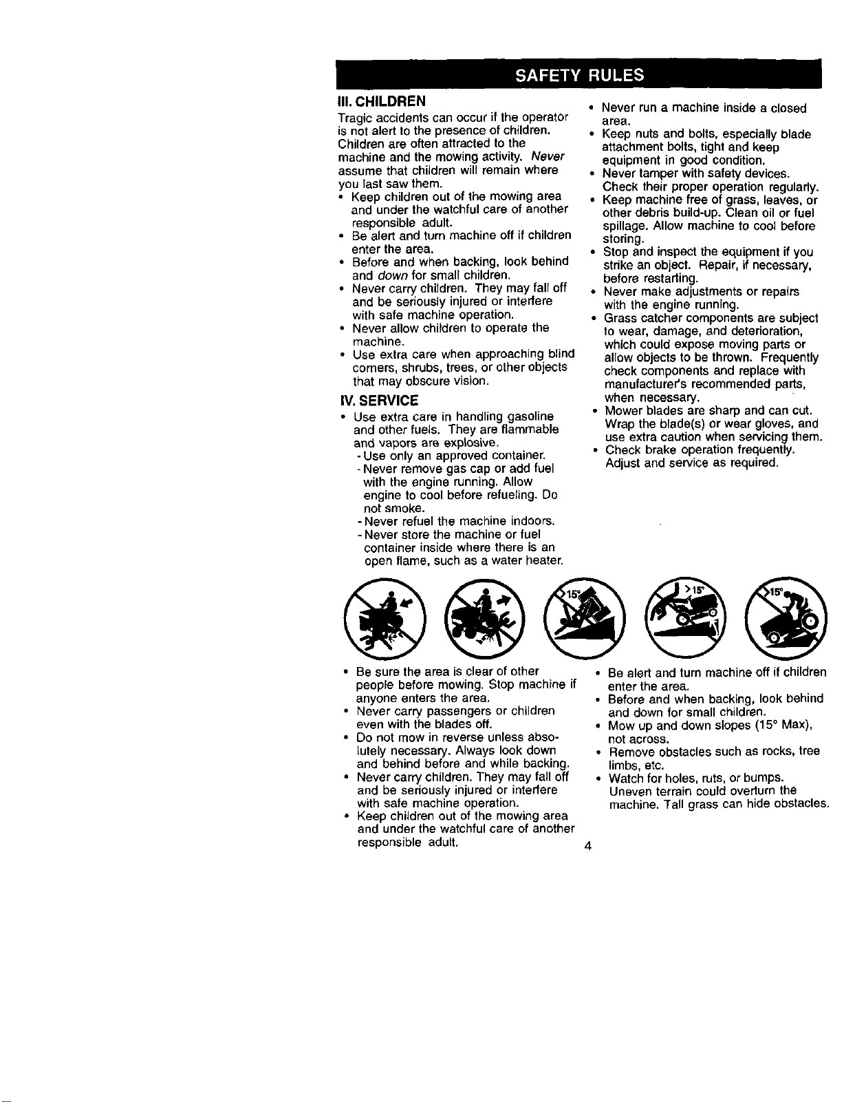
• Mow up and down slopes, not across.
• Remove obstacles such as rocks, tree
limbs, etc.
• Watch for holes, ruts, or bumps.
Uneven terrain could overturn the
machine. Tall grass can hide obstacles.
• Use slow speed. Choose a low gear
so that you will not have to stop or shift
while on the slope.
• Follow the manufacturer's recommen-
dations for wheel weights or counter-
weights to improve stability.
• Use extra care with grass catchers or
other attachments. These can change
the stability of the machine.
• Keep all movement on the slopes slow
and gradual Do not make sudden
changes in speed or direction.
• Avoid starting or stopping on a slope, if
tires lose traction, disengage the
blades and proceed slowly straight
down the slope.
DO NOT:
• Do not turn on slopes unless neces-
sary, and then, turn slowly and gradu-
ally downhill, if possible.
• Do not mow near drop-offs, ditches, or
embankments. The mower could
suddenly turn over if a wheel is over
the edge of a cliff or ditch, or if an edge
eaves in.
• Do not mow on wet grass. Reduced
traction could cause sliding.
• Do not try to stabilize the machine by
putting your foot on the ground.
• Do not use grass catcher on steep
slopes.
III. CHILDREN
Tragic accidents can occur if the operator
is not alert to the presence of children.
Children are often attracted to the
machine and the mowing activity. Never
assume that children will remain where
you last saw them.
• Keep children out of the mowing area
and under the watchful care of another
responsible adult.
• Be alert and turn machine off if children
enter the area.
• Before and when backing, look behind
and down for small children.
• Never carry chiJdren. They may fall off
and be seriously injured or interfere
with safe machine operation.
• Never allow children to operate the
machine.
• Use extra care when approaching blind
corners, shrubs, trees, or other objects
that may obscure vision.
IV. SERVICE
• Use extra care in handling gasoline
and other fuels. They are flammable
and vapors are explosive.
- Use only an approved container.
- Never remove gas cap or add fuel
with the engine running. Allow
engine to cool before refueling. Do
not smoke.
- Never refuel the machine indoors.
- Never store the machine or fuel
container inside where there is an
open flame, such as a water heater.
• Never run a machine inside a closed
area.
• Keep nuts and bolts, especially blade
attachment bolts, tight and keep
equipment in good condition.
• Never tamper with safety devices.
Check their proper operation regularly.
• Keep machine free of grass, leaves, or
other debris build-up. Clean oil or fuel
spillage. Allow machine to cool before
storing.
• Stop and inspect the equipment if you
strike an object. Repair, if necessary,
before restarting.
• Never make adjustments or repairs
with the engine running.
• Grass catcher components are subject
to wear, damage, and deterioration,
which could expose moving parts or
allow objects to be thrown. Frequently
check components and replace with
manufacturer's recommended parts,
when necessary.
• Mower blades are sharp and can cut.
Wrap the blade(s) or wear gloves, and
use extra caution when servicing them.
• Check brake operation frequently.
Adjust and service as required.
• Be sure the area is clear of other
people before mowing. Stop machine if
anyone enters the area.
• Never carry passengers or children
even with the blades off.
• Do not mow in reverse unless abso-
lutely necessary. Always look down
and behind before and while backing,
• Never carry children. They may fall off
and be seriously injured or interfere
with safe machine operation.
• Keep children out of the mowing area
and under the watchful care of another
• Be alert and turn machine off if children
enter the area.
• Before and when backing, look behind
and down for small children.
• Mow up and down slopes (15° Max),
not across.
• Remove obstacles such as rocks, tree
limbs, etc.
• Watch for holes, ruts, or bumps.
Uneven terrain could ovedurn the
machine. Tall grass can hide obstacles,
responsible adult,
4
• Use slow speed. Choose a low gear so
that you will not have to stop or shift
while on the slope.
• Avoid starting or stopping on a slope. If
tires lose traction, disengage the
blades and proceed slowly straight
down the slope.
• If machine stops while going uphill,
disengage blades, shift into reverse
and back down slowly.
• Do not turn on slopes unless neces-
sary, and then, turn slowly and gradu-
ally downhill, if possible.
_.Look for this symbol to point out
important safety precautions. It means
CAUTION!!! BECOMEALERT!!! YOUR
SAFETY IS INVOLVED.
,_ CAUTION: In order to prevent
accidental starting when setting up,
transporting, adjusting or making repairs,
always disconnect spark plug wire and
place wire where it cannot contact spark
plug.
,_lh CAUTION: Do not coast down a hill
in neutral, you may lose control of the
tractor.
_. CAUTION: Tow only the attachments
that are recommended by and comply
with specifications of the manufacturer of
your tractor. Use common sense when
towing. Operate only at the lowest
possible speed when on a slope. Too
heavy of a load, while on a slope, is
dangerous. Tires can lose traction with
the ground and cause you to lose control
of your tractor.
,_WARNING: Engine exhaust, some of
its constituents, and certain vehicle
components contain or emit chemicals
known to the State of California to cause
cancer and birth defects or other repro-
ductive harm.
,_WARNING: Battery posts, terminals
and related accessories contain lead and
lead compounds, chemicars known to the
State of California to cause cancer and
birth defects or other reproductive harm.
Wash hands after handling.
5
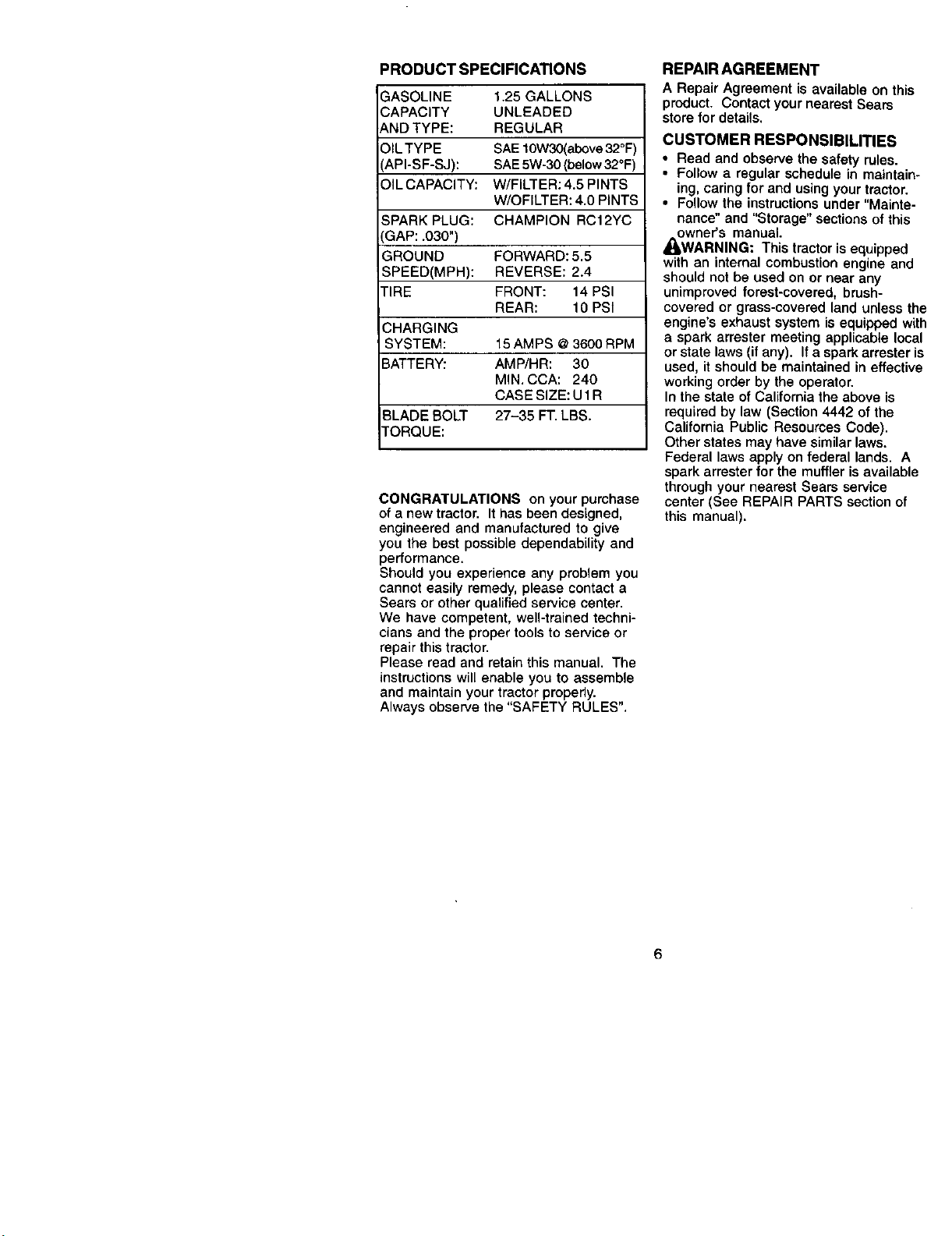
PRODUCT SPECIFICATIONS
3ASOLINE 1.25 GALLONS
CAPACITY UNLEADED
_,ND TYPE: REGULAR
DIL TYPE SAE 10W30(abova 32°F)
_PI-SF-SJ): SAE 5W-30 (below 32°F)
OIL CAPACITY: W/FILTER: 4.5 PINTS
W/OFILTER: 4.0 PINTS
SPARK PLUG: CHAMPION RC12YC
GAP: .030")
GROUND FORWARD: 5.5
SPEED(MPH): REVERSE: 2.4
TIRE FRONT: 14 PSI
REAR: 10 PSI
CHARGING
SYSTEM: 15 AMPS @ 3600 RPM
BATTERY: AMP/HR: 30
MIN. CCA: 240
CASE SIZE: U 1R
BLADE BOLT 27-35 FT. LBS.
TORQUE:
CONGRATULATIONS on your purchase
of a new tractor. It has been designed,
engineered and manufactured to give
you the best possible dependability and
performance.
Should you experience any problem you
cannot easily remedy, please contact a
Sears or other qualified service center.
We have competent, well-trained techni-
cians and the proper tools to service or
repair thistractor.
Please read and retain this manual. The
instructions will enable you to assemble
and maintain your tractor properly.
Always observe the "SAFETY RULES".
REPAIR AGREEMENT
A Repair Agreement is available on this
product. Contact your nearest Sears
store for details.
CUSTOMER RESPONSIBILITIES
• Read and observe the safety rules.
• Follow a regular schedule in maintain-
ing, caring for and using your tractor.
• Follow the instructions under "Mainte-
nance" and "Storage" sections of this
owner's manual.
,_WARNING: This tractor is equipped
with an internal combustion engine and
should not be used on or near any
unimproved forest-covered, brush-
covered or grass-covered land unless the
engine's exhaust system is equipped with
a spark arrester meeting applicable local
or state laws (if any). Ifa spark arrester is
used, it should be maintained in effective
working order by the operator.
In the state of California the above is
required by law (Section 4442 of the
California Public Resources Code).
Other states may have similar laws.
Federal laws apply on federal lands. A
spark arraster for the muffler is available
through your nearest Sears service
center (See REPAIR PARTS section of
this manual).
6
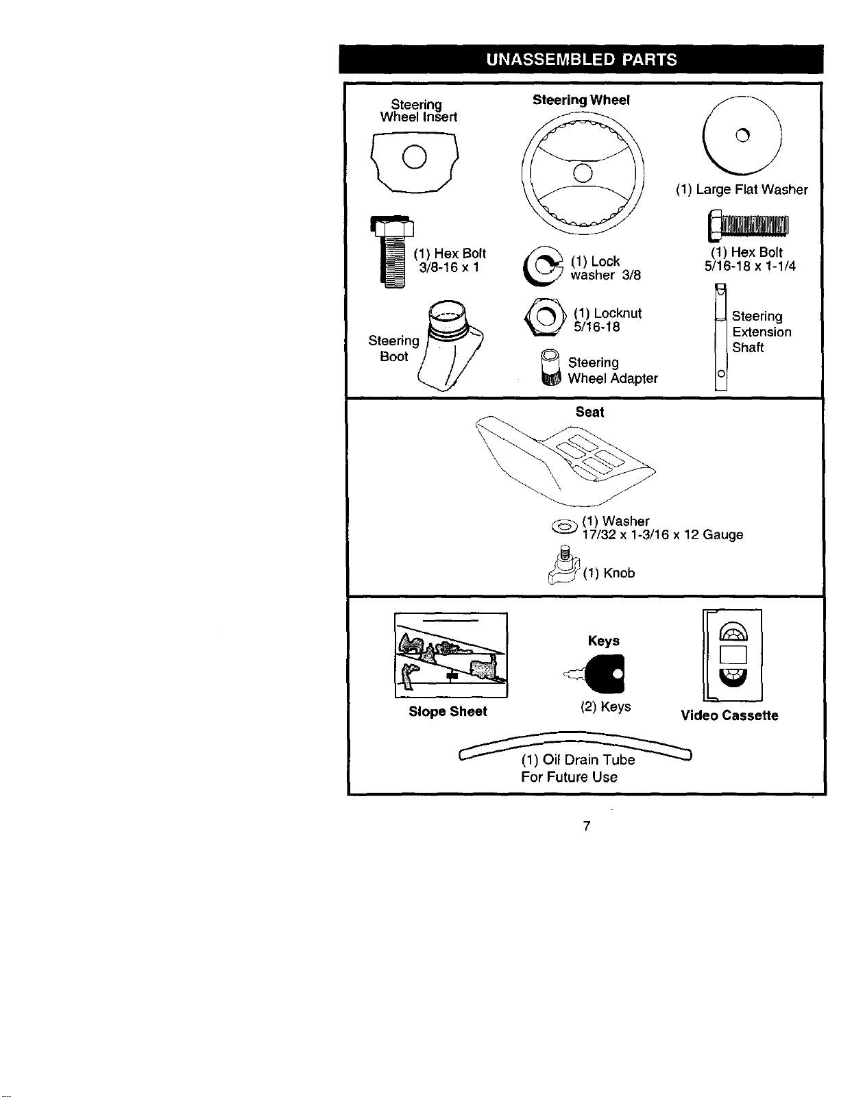
Steering
Wheel Insert
I_(1) Hex Bolt
3/8-16 x 1
Steering _
Boot
Steering Wheel
(1) Lockwasher 3/8
(1) Locknut
5/16-18
_ Steering
Wheel Adapter
Seat
(1) Large Flat Washer
(1) Hex Bolt
5/16-18 x 1-1/4
Steering
Extension
Shaft
_(1) Washer
17/32 x 1-3/16 x 12 Gauge
_(1) Knob
Slope Sheet
Keys
I1
(2) Keys Video Cassette
For Future Use
7
Your new tractor has been assembled at the factory with exception of those parts left
unassembled for shipping purposes. To ensure safe and proper operation of your
tractor all parts and hardware you assemble must be tightened securely. Use the
correct tools as necessary to insure proper tightness. Review the video cassette before
you begin.
TOOLS REQUIRED FOR ASSEMBLY
A socket wrench set will make assembly
easier. Standard wrench sizes you need
are listed below.
(1) 9/16" wrench (1) Pliers
(2) 1/2" wrench (1) Utility knife
(1) Tire pressure gauge
When right or left hand is mentioned in
this manual, it means, from your point of
view, when you are in the operating
position (seated behind the steering
wheel).
TO REMOVE TRACTOR FROM
CARTON
UNPACK CARTON
1. Remove all accessible loose parts
and parts cartons from carton.
2. Cut, from top to bottom, along lines on
all four corners of carton, and lay
panels flat.
3. Check for any additional loose parts
or cartons and remove.
BEFORE REMOVING TRACTOR
FROM SKID
A'n'ACH STEERING WHEEL
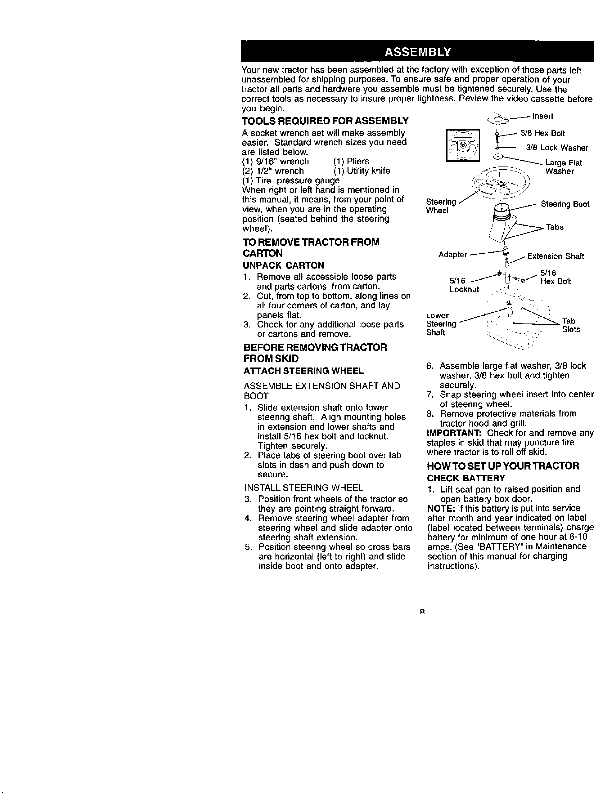
ASSEMBLE EXTENSION SHAFT AND
BOOT
1. Slide extension shaft onto lower
steering shaft. Align mounting holes
in extension and lower shafts and
install 5/16 hex bolt and Iocknut.
Tighten securely.
2. Place tabs of steering boot over tab
slots in dash and push down to
secure.
INSTALL STEERING WHEEL
3. Position front wheels of the tractor so
they are pointing straight forward.
4. Remove steering wheel adapter from
steering wheel and slide adapter onto
steering shaft extension.
5. Position steering wheel so cross bars
are horizontal (left to right) and slide
inside boot and onto adapter.
_ Insert
_ 3/8 Hex Bolt
3/8 LockWasher
_ LargeFlat
://_.\ Washer
SteeringF -_......_ SteedngBoot
Wheel _
Adapter_ _ ExtensionShaft
5/16 _ L / 5/16
J _ Hex Bolt
Locknut - "_
6. Assemble large flat washer, 3/8 lock
washer, 3/8 hex bolt and tighten
securely.
7. Snap steering wheel insert into center
of steering wheel.
8. Remove protective materials from
tractor hood and grill.
IMPORTANT: Check for and remove any
staples in skid that may puncture tire
where tractor is to roll off skid.
HOW TO SET UP YOUR TRACTOR
CHECK BATTERY
1. Lift seat pan to raised position and
open battery box door.
NOTE: If this battery is put into service
after month and year indicated on label
(label located between terminals) charge
battery for minimum of one hour at 6-10
amps. (See "BATTERY" in Maintenance
section of this manual for charging
instructions).
R
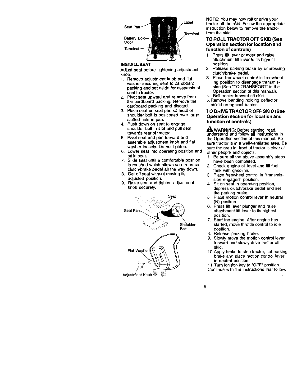
Label
Battery
Door
Terminal
INSTALL SEAT
Adjust seat before tightening adjustment
knob.
1. Remove adjustment knob and flat
washer securing seat to cardboard
packing and set aside for assembly of
seat to tractor.
2. Pivot seat upward and remove from
the cardboard packing. Remove the
cardboard packing and discard.
3. Place seat on seat pan so head of
shoulder bolt is positioned over large
slotted hole in pan.
4. Push down on seat to engage
shoulder bolt in slot and pull seat
towards rear of tractor.
5. Pivot seat and pan forward and
assemble adjustment knob and flat
washer loosely. Do not tighten.
6. Lower seat into operating position and
sit in seat.
7. Slide seat until a comfortable position
is reached which allows you to press
clutch/brake pedal all the way down.
8. Get off seat without moving its
adjusted position.
9. Raise seat and tighten adjustment
knob securely.
, Seat
J
Seat Pan_ _
_"_"_ Shoulder
_::_3_ Bort
Flat
NOTE: You may now roll or drive your
tractor off the skid. Follow the appropriate
instruction below to remove the tractor
from the skid.
TO ROLL TRACTOR OFF SKID (See
Operation section for location and
function of controls)
1. Press lift lever plunger and raise
attachment lift lever to its highest
position.
2. Release parking brake by depressing
clutch/brake pedal.
3. Place freewheel control in freewheel-
ing position to disengage transmis-
sion (See "TO TRANSPORT" in the
Operation section of this manual).
4. Roll tractor forward off skid.
5. Remove banding holding deflector
shield up against tractor.
TO DRIVE TRACTOR OFF SKID (See
Operation section for location and
function of controls)
WARNING: Before starting, read,
understand and follow all instructions in
the Operation section of this manual, Be
sure tractor is in a well-ventilated area, Be
sure the area in front oftractor is clear of
other people and objects.
1. Be sure all the above assembly steps
have been completed.
2. Check engine oil level and fill fuel
tank with gasoline.
3. Place freewheel control in "transmis-
sion engaged" position.
4. Sit on seat in operating position,
depress clutch/brake pedal and set
the parking brake,
5. Place motion control lever in neutral
(N) position.
6. Press lift lever plunger and raise
attachment lift lever to its highest
position.
7. Start the engine. After engine has
started, move throttle control to idle
position.
8. Release parking brake.
9. Slowly move the motion control lever
forward and slowly drive tractor off
skid.
10.Apply brake to stop tractor, set parking
brake and place motion control lever
in neutral position,
11.Turn ignition key to "OFF" position.
Continue with the instructions that follow.
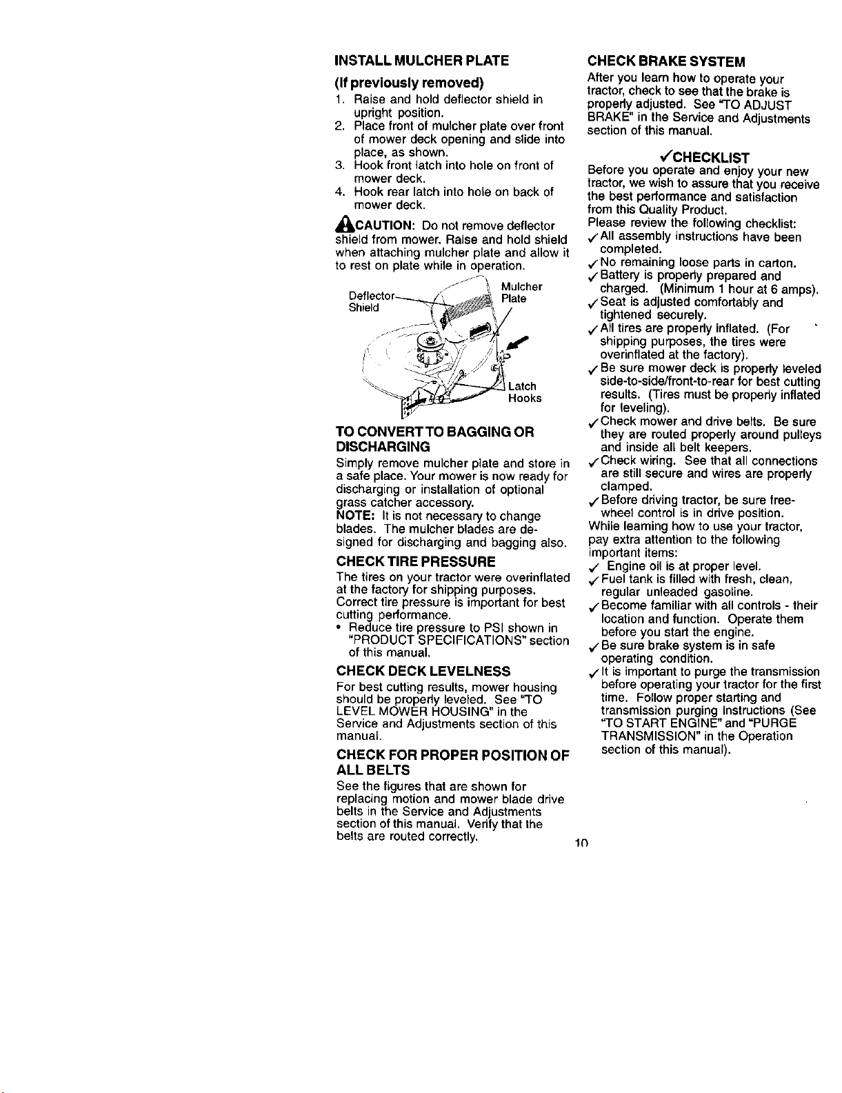
INSTALL MULCHER PLATE
(If previously removed)
1. Raise and hold deflector shield in
upright position.
2. Place front of mulcher plate over front
of mower deck opening and slide into
place, as shown.
3. Hook front latch into hole on front of
mower deck.
4. Hook rear latch into hole on back of
mower deck.
,_CAUTION: Do not remove deflector
shield from mower. Raise and hold shield
when attaching mulcher plate and allow it
to rest on plate while in operation.
J _! Mulcher
Plate
Shield
Hooks
TO CONVERT TO BAGGING OR
DISCHARGING
Simply remove mulcher plate and store in
a safe place. Your mower is now ready for
discharging or installation of optional
grass catcher accessory.
NOTE: It is not necessary to change
blades. The mulcher blades are de-
signed for discharging and bagging also.
CHECK TIRE PRESSURE
The tires on your tractor were overinflated
at the factory for shipping purposes.
Correct tire pressure is important for best
cutting performance.
• Reduce tire pressure to PSI shown in
"PRODUCT SPECIFICATIONS" section
of this manual.
CHECK DECK LEVELNESS
For best cutting results, mower housing
should be properly leveled. See "TO
LEVEL MOWER HOUSING" in the
Service and Adjustments section of this
manual.
CHECK FOR PROPER POSITION OF
ALL BELTS
See the figures that are shown for
replacing motion and mower blade drive
belts in the Service and Adjustments
section of this manual. Verify that the
belts are routed correctly. 1¢}
CHECK BRAKE SYSTEM
After you learn how to operate your
tractor, check to see that the brake is
properly adjusted. See "TO ADJUST
BRAKE" in the Service and Adjustments
section of this manual.
V"CHECKLIST
Before you operate and enjoy your new
tractor, we wish to assure that you receive
the best performance and satisfaction
from this Quality Product.
Please review the following checklist:
,/'All assembly instructions have been
completed.
v'No remaining loose parts in carton.
V Battery is propedy prepared and
charged. (Minimum 1 hour at 6 amps).
v'Seat is adjusted comfortably and
tightened securely.
vAIl tires are properly inflated. (For
shipping purposes, the tires were
overinflated at the factory).
V"Be sure mower deck is properly leveled
side-to-side/front-to-rear for best cutting
results. (Tires must be property inflated
for leveling).
,/'Check mower and drive belts. Be sure
they are routed properly around pulleys
and inside all belt keepers.
,/'Check wiring. See that all connections
are still secure and wires are properly
clamped.
V"Before driving tractor, be sure free-
wheel control is in drive position.
While learning how to use your tractor,
pay extra attention to the following
important items:
,/ Engine oil is at proper level.
v" Fuel tank is filled with fresh, clean,
regular unleaded gasoline.
v" Become familiar with all controls - their
location and function. Operate them
before you start the engine.
V"Be sure brake system is in safe
operating condition.
V"It is important to purge the transmission
before operating your tractor for the first
time. Follow proper starting and
transmission purging instructions (See
"TO START ENGINE" and "PURGE
TRANSMISSION" in the Operation
section of this manual).
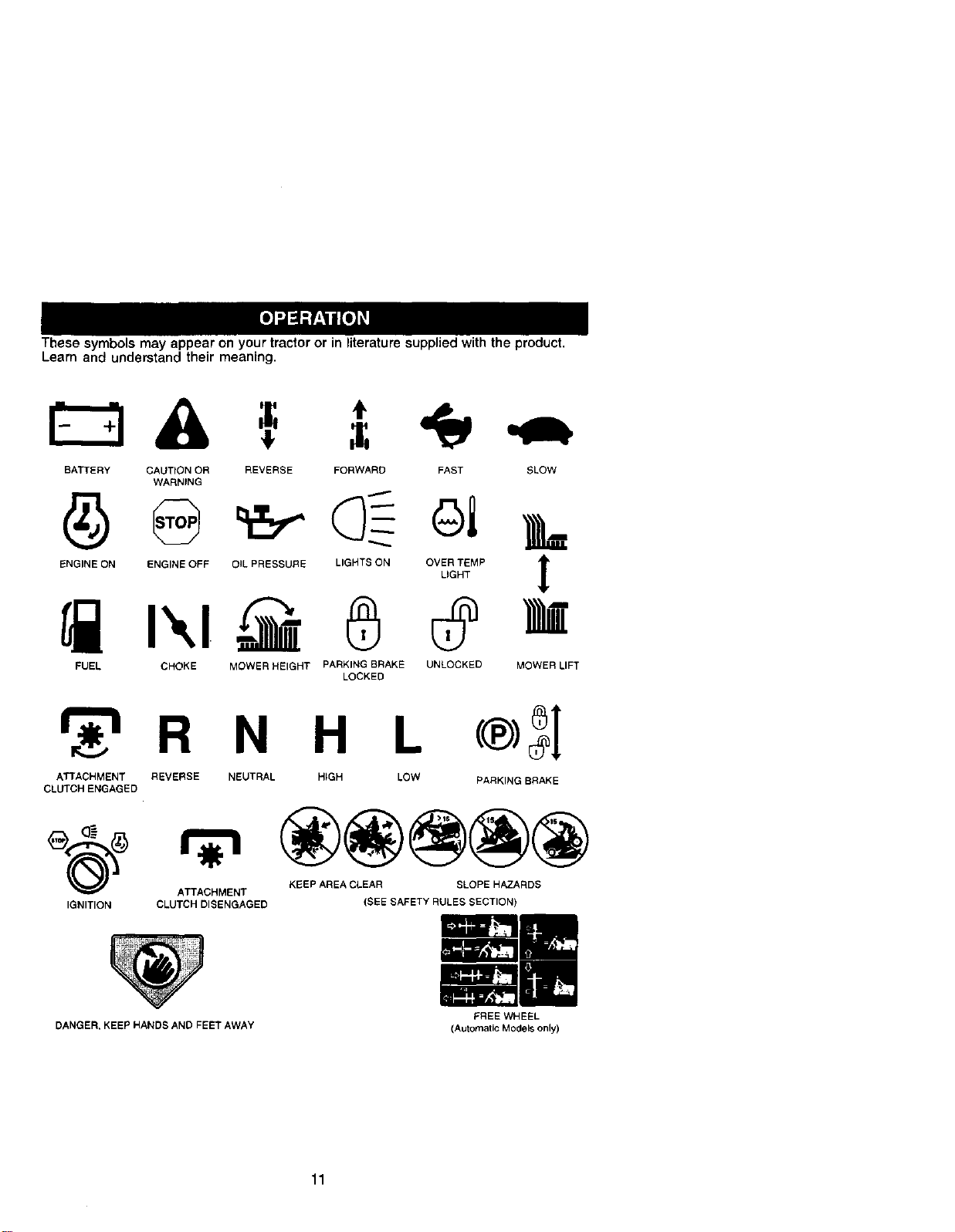
Thesesymbols may appear on your tractor or in literature supplied with the product.
Learn and understand their meaning.
BATTERY CAUTION OR REVERSE FORWARD FAST SLOW
WARNING
ENGINE ON ENGINE OFF OIL PRESSURE LIGHTS ON OVER TEMP t
LIGHT
!
FUEL CHOKE MOWER HEIGHT PARKING BRAKE UNLOCKED
LOCKED
MOWER LIFT
_r_"lR N H L (®)_[
ATTACHMENT REVERSE NEUTRAL HIGH LOW PARKING BRAKE
CLUTCH ENGAGED
ATTACHMENT KEEP AREA CLEAR SLOPE HAZARDS
IGNITION CLUTCH DISENGAGED (SEE SAFETY RULES SECTION)
DANGER, KEEP HANDS AND FEET AWAY
11
FREE WHEEL
(Automatic Models only)
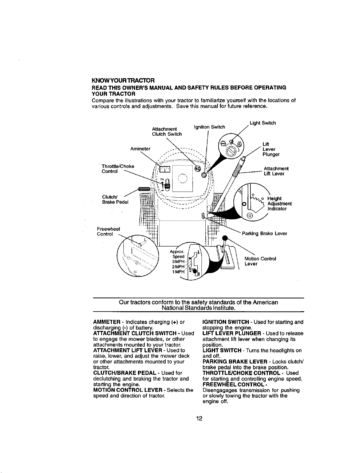
KNOWYOUR TRACTOR
READ THIS OWNER'S MANUAL AND SAFETY RULES BEFORE OPERATING
YOUR TRACTOR
Compare the illustrations with your tractor to familiarize yourself with the locations of
various controls and adjustments. Save this manual for future reference.
Attachment
Clutch Switch
Ammeter
Ignition Switch
Light Switch
Lift
Lever
Plunger
Throttle/Choke Attachment
Control _ LiftLever
Clutch/ Height
Brake Pedat Adjustment
Indicator
Froewheel
Control
Parking Brake Lever
MoUon Control
Lever
Our tractors conform to the safety standards ofthe American
National Standards Institute.
AMMETER - Indicates charging (+) or
discharging (-) of battery.
ATTACHMENT CLUTCH SWITCH - Used
to engage the mower blades, or other
attachments mounted to your tractor.
ATTACHMENT LIFT LEVER - Used to
raise, lower, and adjust the mower deck
or other attachments mounted to your
tractor.
CLUTCH/BRAKE PEDAL - Used for
declutching and braking the tractor and
starting the engine.
MOTION CONTROL LEVER - Selects the
speed and direction of tractor,
IGNITION SWITCH - Used for starting and
stopping the engine.
LIFT LEVER PLUNGER - Used to release
attachment lift lever when changing its
position.
LIGHT SWITCH - Turns the headlights on
and off.
PARKING BRAKE LEVER - Locks clutch/
brake pedal into the brake position.
TRRO'rFLE/CHOKE CONTROL - Used
for starting and controlling engine speed.
FREEWHEEL CONTROL-
Disengagages transmission for pushing
or slowly towing the tractor with the
engine off.
12
The operation of any tractor can result in foreign objects thrown into the
which can result in severe eye damage. Always wear safety
I
glasses or eye shields while operating your tractor or performing any
adjustments or repairs. We recommend a wide vision safety mask over
spectacles or standard safety glasses.
"Disengaged" "Brake"
Position Position
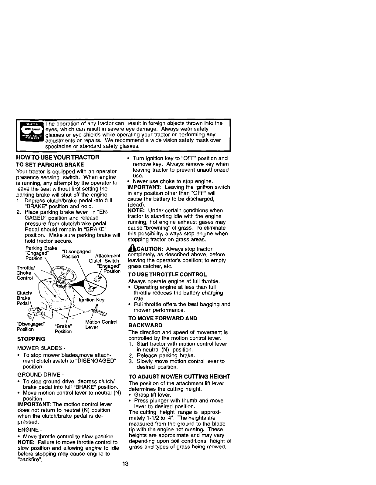
HOW TO USE YOUR TRACTOR
TO SET PARKING BRAKE
Your tractor is equipped with an operator
presence sensing switch. When engine
is running, any attempt by the operator to
leave the seat without first setting the
parking brake will shut off the engine.
1. Depress clutch/brake pedal into full
"BRAKE" position and hold.
2. Place parking brake lever in "EN-
GAGED" position and release
pressure from clutch/brake pedal.
Pedal should remain in "BRAKE"
position. Make sure parking brake will
hold tractor secure.
Parking Brake
.En,_,,ed,, "Disengaged"
p _ _ Position Attachment
,os,,,on \ \ Clutch Switch
"Engaged"
Throttle/ _'-_" \ -- Position
Choke.. "--k\ \f-y.."
cont,o,
c,otc /
Brake _\;_ \/'_- _f I_nition Key
Peaal , "
Lever
STOPPING
MOWER BLADES -
• To stop mower blades,move attach-
ment clutch switch to "DISENGAGED"
position.
GROUND DRIVE -
• To stop ground ddve. depress clutch/
brake pedal into full "BRAKE" position.
• Move motion control lever to neutral (N)
position.
IMPORTANT: The motion control lever
does not return to neutral (N) position
when the clutch/brake pedal is de-
pressed.
ENGINE -
• Move throttle control to slow position.
NOTE: Failure to move throttle control to
slow position and allowing engine to idle
before stopping may cause engine to
"backfire".
• Turn ignition key to "OFF" position and
remove key. Always remove key when
leaving tractor to prevent unauthorized
use.
• Never use choke to stop engine.
IMPORTANT= Leaving the ignition switch
in any position other than "OFF" will
cause the battery to be discharged,
(dead).
NOTE: Under certain conditions when
tractor is standing idle with the engine
running, hot engine exhaust gases may
cause "browning" of grass. To eliminate
this possibility, always stop engine when
stopping tractor on grass areas.
_I_CAUTION: Always stop tractor
completely, as described above, before
leaving the operator's position; to empty
grass catcher, etc.
TO USE THROTTLE CONTROL
Always operate engine at full throttle,
• Operating engine at less than full
throttle reduces the battery charging
rate.
• Full throttle offers the best bagging and
mower performance.
TO MOVE FORWARD AND
BACKWARD
The direction and speed of movement is
controlled by the motion control lever.
1. Start tractor with motion control lever
in neutral (N) position,
2. Release parking brake.
3. Slowly move motion control lever to
desired position.
TO ADJUST MOWER CUTTING HEIGHT
The position of the attachment liftlever
determines the cutting height.
• Grasp liftlever.
• Press plunger with thumb and move
lever to desired position.
The cutting height range is approxi-
mately 1-1/2 to 4". The heights are
measured from the ground to the blade
tip with the engine not running. These
heights are approximate and may vary
depending upon soil conditions, height of
grass and types of grass being mowed.
13
• The average lawn should be cut to
approximately 2.1/2 inches during the
cool season and to over 3 inches
during hot months. For healthier and
better tooking lawns, mow often and
after moderate growth.
• For best cutting performance, grass
over 6 inches in height should be
mowed twice. Make the first cut
relatively high; the second to desired
height.
TO ADJUST GAUGE WHEELS
Gauge wheels are properly adjusted
when they are slightly off the ground
when mower is at the desired cutting
height in operating position. Gauge
wheels then keep the deck in proper
position to help prevent scalping in most
terrain conditions.
NOTE: Adjust gauge wheels with tractor
on a flat level surface.
1. Adjust mower to desired cutting height
(See TO ADJUST MOWER CUTTING
HEIGHT" in the Operation section of
this manual).
2. With mower in desired height of cut
position, gauge wheels should be
assembled so they are slightly off the
ground, Install gauge wheel in
appropriate hote with shoulder bolt,
3/8 washer, and 3/8-16 Iocknut and
tighten securely.
3. Repeat for opposite side installing
gauge wheel in same adjustment
hole.
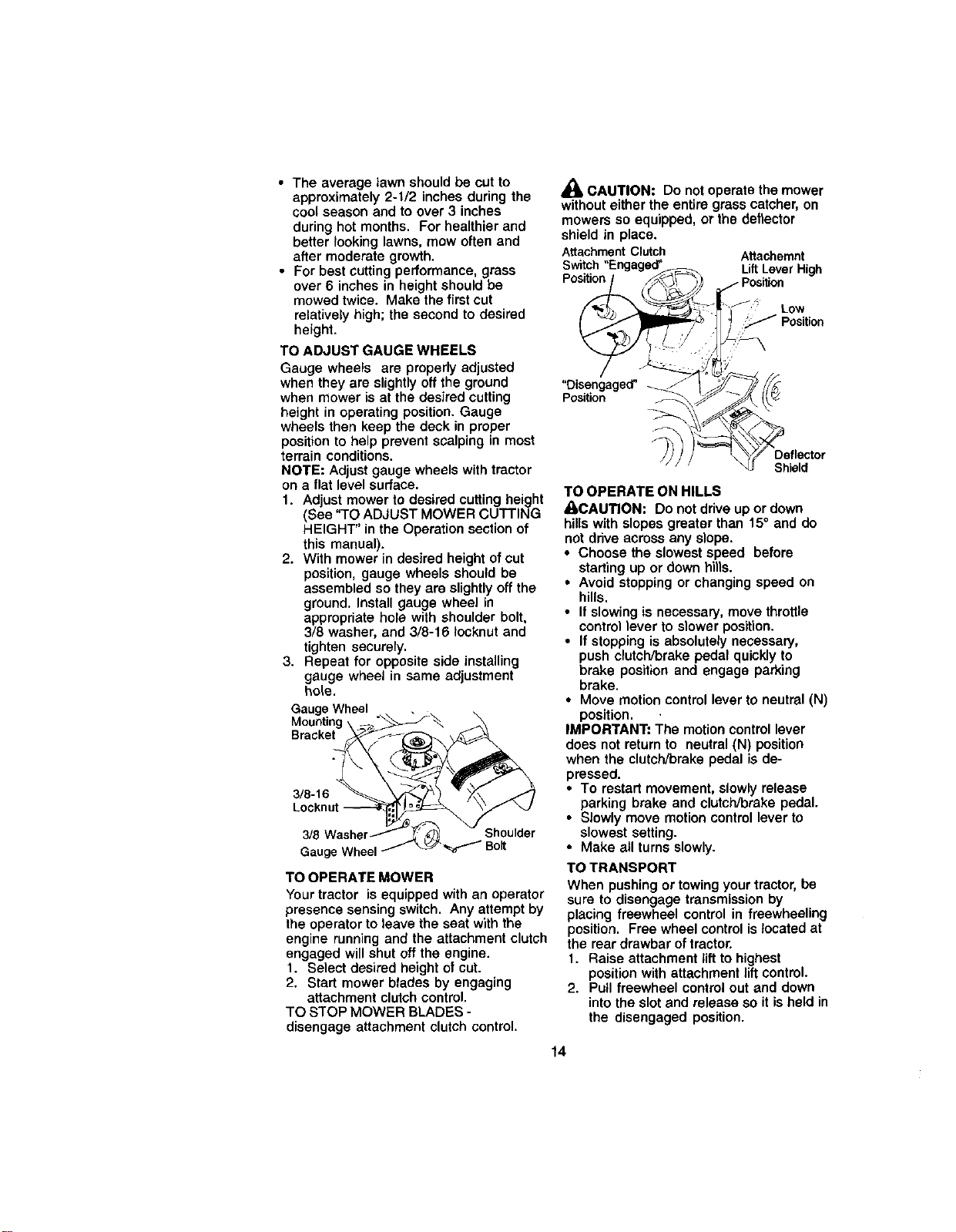
Gauge Wheel
Bracket
3/8-16
3/8 Shoulder
Gaug_
TO OPERATE MOWER
Your tractor is equipped with an operator
presence sensing switch. Any attempt by
the operator to leave the seat with the
engine running and the attachment clutch
engaged will shut off the engine.
1. Select desired height of cut.
2. Start mower blades by engaging
attachment clutch control.
TO STOP MOWER BLADES -
disengage attachment clutch control.
,_ CAUTION: Do not operate the mower
without either the entire grass catcher, on
mowers so equipped, or the deflector
shield in place,
Attachment Clutch Attachemnt
LiftLeverHigh
Position
Low
"Disengaged"
Position
Shield
TO OPERATE ON HILLS
_CAUT/ON: Do not drive up or down
hills with slopes greater than 15° and do
not drive across any slope.
• Choose the slowest speed before
starting up or down hills.
• Avoid stopping or changing speed on
hills,
• If slowing is necessary, move throttle
control lever to slower position.
• If stopping is absolutely necessary,
push clutch/brake pedal quickly to
brake position and engage parking
brake.
• Move motion control lever to neutral (N)
position. ,
IMPORTANT= The motion control lever
does not return to neutral (N) position
when the clutch/brake pedal is de-
pressed.
• To restart movement, slowly release
parking brake and clutch/brake pedal.
• Slowly move motion control lever to
slowest setting.
• Make all turns slowly.
TO TRANSPORT
When pushing or towing your tractor, be
sure to disengage transmission by
placing freewheel control in freewheeling
position. Free wheel control is located at
the rear drawbar of tractor.
1. Raise attachment lift to highest
position with attachment liftcontrol.
2. Pull freewheel control out and down
into the slot and release so it is held in
the disengaged position.
14
• Do not push or tow tractor at more than
two (2) MPH.
• To reengage transmission, reverse
'above procedure.
NOTE: To protect hood from damage
when transporting your tractor on a truck
or a trailer, be sure hood is closed and
secured to tractor. Use an appropriate
means of tying hood to tractor (rope, cord,
etc.).
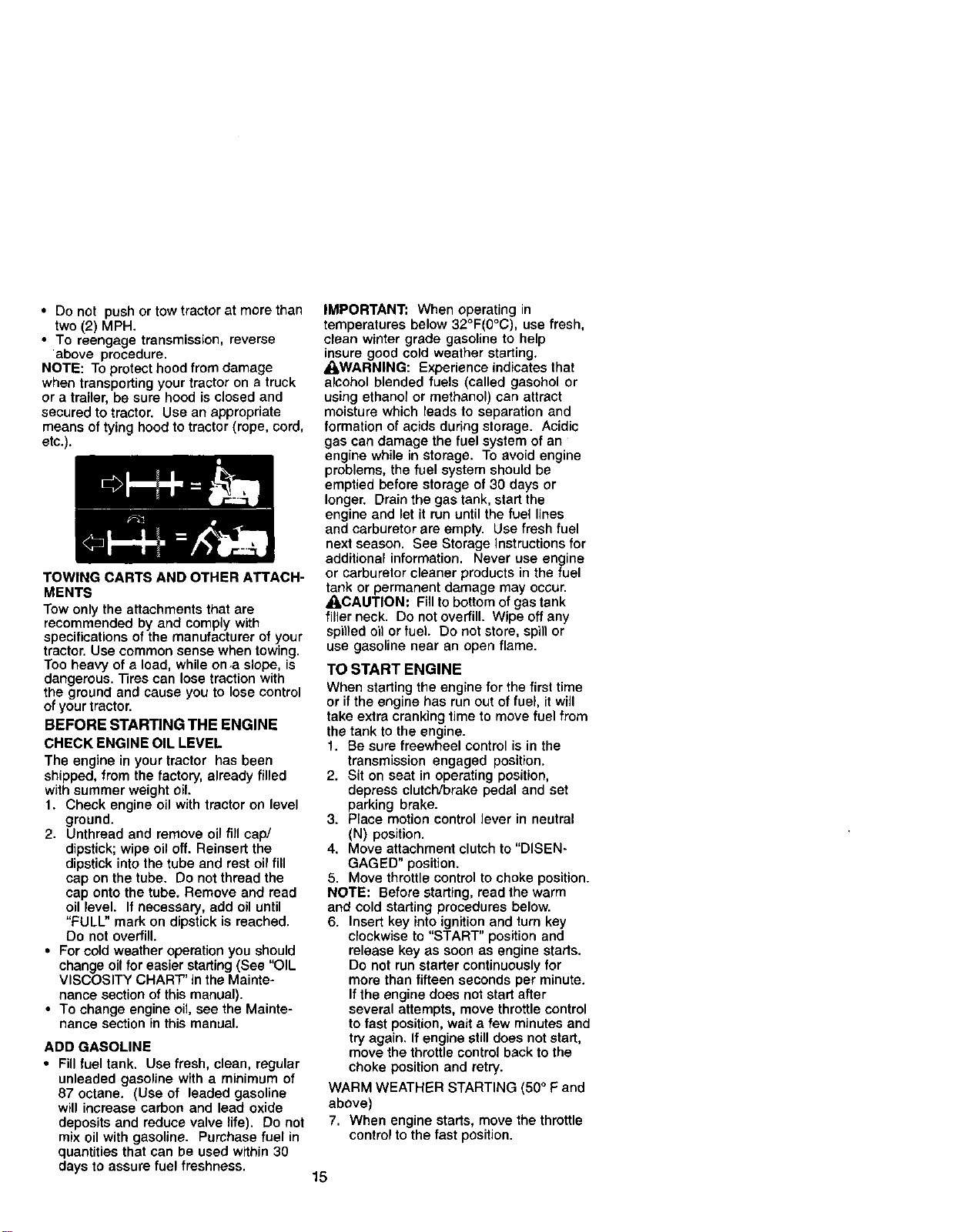
TOWING CARTS AND OTHER ATTACH-
MENTS
Tow only the attachments that are
recommended by and comply with
specifications of the manufacturer of your
tractor. Use common sense when towing.
Too heavy of a load, while on.a slope, is
dangerous. Tires can lose traction with
the ground and cause you to lose control
of yourtractor.
BEFORE STARTING THE ENGINE
CHECK ENGINE OIL LEVEL
The engine in your tractor has been
shipped, from the factory, already filled
with summer weight oil.
1. Check engine oil with tractor on level
ground.
2. Unthread and remove oil fill cap/
dipstick; wipe oil off. Reinsert the
dipstick into the tube and rest oil fill
cap on the tube. Do not thread the
cap onto the tube. Remove and read
oil level. If necessary, add oil until
"FULL" mark on dipstick is reached.
Do not overfill.
• For cold weather operation you should
change oil for easier starting (See "OIL
VISCOSITY CHART' in the Mainte-
nance section of this manual).
• To change engine oil, see the Mainte-
nance section in this manual.
ADD GASOLINE
• Fill fuel tank. Use fresh, clean, regular
unleaded gasoline with a minimum of
87 octane. (Use of leaded gasoline
will increase carbon and lead oxide
deposits and reduce valve life). Do not
mix oil with gasoline. Purchase fuel in
quantities that can be used within 30
days to assure fuel freshness.
IMPORTANT: When operating in
temperatures below 32°F(0°C), use fresh,
clean winter grade gasoline to help
insure good cold weather starting.
_kWARNING: Experience indicates that
alcohol blended fuels (called gasohol or
using ethanol or methanol) can attract
moisture which leads to separation and
formation of acids during storage. Acidic
gas can damage the fuel system of an
engine while in storage. To avoid engine
problems, the fuel system should be
emptied before storage of 30 days or
longer. Drain the gas tank, start the
engine and let it run until the fuel lines
and carburetor are empty. Use fresh fuel
next season. See Storage Instructions for
additional information. Never use engine
or carburetor cleaner products in the fuel
tank or permanent damage may occur.
_kCAUTION: Fill to bottom of gas tank
filler neck. Do not overfill. Wipe off any
spil)ed oil or fuel. Do not store, spill or
use gasoline near an open flame.
TO START ENGINE
When starting the engine for the first time
or if the engine has run out of fuel, it will
take extra cranking time to move fuel from
the tank to the engine.
1. Be sure freewheel control is in the
transmission engaged position.
2. Sit on seat in operating position,
depress clutch/brake pedal and set
parking brake.
3. Place motion control lever in neutral
(N) position.
4. Move attachment clutch to "DISEN-
GAGED" position.
5. Move throttle control to choke position.
NOTE: Before starting, read the warm
and cold starting procedures below.
6. Insert key into ignition and turn key
clockwise to "START" position and
release key as soon as engine starts.
Do not run starter continuously for
more than fifteen seconds per minute.
If the engine does not start after
several attempts, move throttle control
to fast position, wait a few minutes and
try again. If engine still does not start,
move the throttle control back to the
choke position and retry.
WARM WEATHER STARTING (50° F and
above)
7. When engine starts, move the throttle
control to the fast position.
15
• The attachments and ground drive can
now be used. If the engine does not
accept the load, restart the engine and
allow it to warm up for one minute
using the choke as described above.
COLD WEATHER STARTING ( 50° F and
below)
7. When engine starts, allow engine to
run with the throttle control in the
choke position until the engine runs
roughly, then move throttle control to
fast position. This may require an
engine warm-up period from several
seconds to several minutes, depend-
ing on the temperature.
AUTOMATIC TRANSMISSION WARM UP
Before driving the unit in cold weather,
the transmission should be warmed up as
follows:
1. Be sure the tractor is on level ground.
2. Place the motion control lever in
neutral. Release the parking brake
and let the clutch/brake slowly return
to operating position.
3. Allow one minute for transmission to
warm up. This can be done during
the engine warm up pedod.
• The attachments can also be used
during the engine warm-up period after
the transmission has been warmed up.
NOTE: if at a high altitude (above 3000
feet) or in cold temperatures (below 32 F)
the carburetor fuel mixture may need to
be adjusted for best engine performance.
See "TO ADJUST CARBURETOR" in the
Service and Adjustments section of this
manual.
PURGE TRANSMISSION
_CAUTION: Never engage or disen-
gage freewheel lever while the engine is
running.
To ensure proper operation and perfor-
mance, it is recommended that the
transmission be purged before operating
tractor for the first time. This procedure will
remove any trapped air inside the
transmission which may have developed
during shipping of your tractor.
IMPORTANT= Should your transmission
require removal for service or replace-
ment, it should be purged after reinstalla-
tion before operating the tractor.
1. Place tractor safely on level surface
with engine off and parking brake set.
2. Disengage transmission by placing
freewheel control in freewheeling
position (See "TO TRANSPORT" in
this section of manual).
3. Sitting in the tractor seat, start engine.
After the engine is running, move
throttle control to slow position. With
motion control lever in neutral (N)
position, slowly disengage clutch/
brake pedal.
4. Move motion control lever to full
forward position and hold for five (5)
seconds. Move lever to full reverse
position and hold for five (5) seconds.
Repeat this procedure three (3) times.
NOTE; During this procedure there will be
no movement of drive wheels. The air is
being removed from hydraulic drive
system.
5. Move motion control lever to neutral
(N) position. Shut- off engine and set
parking brake.
6. Engage transmission by placing
freewheel control in driving position
(See "TO TRANSPORT" in this section
of manual).
7. Sitting in the tractor seat, start engine.
After the engine is running, move
throttle control to half (1/2) speed. With
motion control lever in neutral (N)
position, slowly disengage clutch/
brake pedal.
8. Slowly move motion control lever
forward, after the tractor moves
approximately five (5) feet, slowly
move motion control lever to reverse
position. After the tractor moves
approximately five (5) feet return the
motion control lever to the neutral (N)
position. Repeat this procedure with
the motion control lever three (3)
times.
Your tractor is now purged and now ready
for normal operation.
16
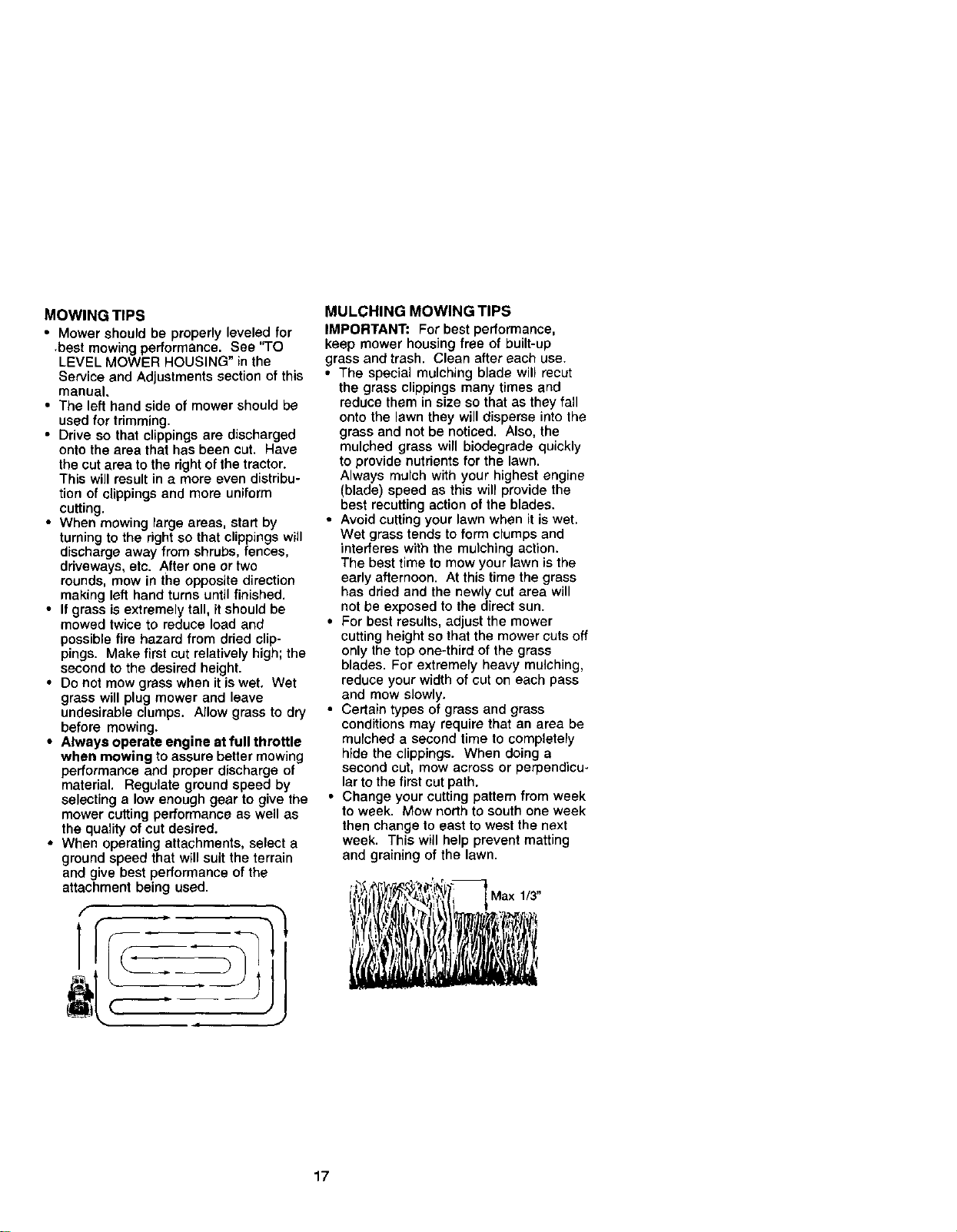
MOWING TIPS
• Mower should be properly leveled for
•best mowing performance. See "TO
LEVEL MOWER HOUSING" in the
Service and Adjustments section of this
manual.
• The left hand side of mower should be
used for trimming.
• Drive so that clippings are discharged
onto the area that has been cut. Have
the cut area to the right of the tractor.
This will result in a more even distribu-
tion of clippings and more uniform
cutting.
• When mowing large areas, start by
turning to the right so that clippings will
discharge away from shrubs, fences,
driveways, etc. After one or two
rounds, mow in the opposite direction
making left hand turns until finished.
• If grass is extremely tall, it should be
mowed twice to reduce load and
possible fire hazard from dried clip-
pings. Make first cut relatively high; the
second to the desired height.
• Do not mow grass when it is wet, Wet
grass will plug mower and leave
undesirable clumps. Allow grass to dry
before mowing.
• Always operate engine at full throttle
when mowing to assure better mowing
performance and proper discharge of
material. Regulate ground speed by
selecting a low enough gear to give the
mower cutting performance as well as
the quality of cut desired.
• When operating attachments, select a
ground speed that will suit the terrain
and give best performance of the
attachment being used.
MULCHING MOWING TIPS
IMPORTANT: For best performance,
keep mower housing free of built-up
grass and trash. Clean after each use.
• The special mulching blade will recut
the grass clippings many times and
reduce them in size so that as they fall
onto the lawn they will disperse into the
grass and not be noticed. Also, the
mulched grass will biodegrade quickly
to provide nutrients for the lawn.
Always mulch with your highest engine
(blade) speed as this will provide the
best recutting action of the blades.
• Avoid cutting your lawn when it is wet.
Wet grass tends to form clumps and
interferes with the mulching action.
The best time to mow your lawn is the
early afternoon. At this time the grass
has dried and the newly cut area will
not be exposed to the direct sun.
• For best results, adjust the mower
cutting height so that the mower cuts off
only the top one-third of the grass
blades. For extremely heavy mulching,
reduce your width of cut on each pass
and mow slowly.
• Certain types of grass and grass
conditions may require that an area be
mulched a second time to completely
hide the clippings. When doing a
second cut, mow across or perpendicu-
lar to the first cut path.
• Change your cutting pattern from week
to week. Mow north to south one week
then change to east to west the next
week. This will help prevent matting
and graining of the lawn.
Max 1/3"
17
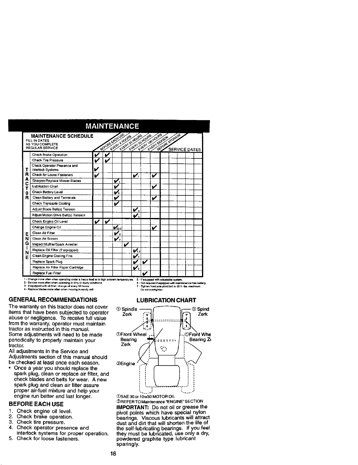
MAINTENANCE SCHEDULE
FILL IN DATES
AS YOU COMPLETE
REGULAR SERV$CE
Check Brake Operation
Check Tire Pressure I_
Check Operator Presence and
InterlOck Systems I_
Check for Loose Fasteners
Sharpen!Replace Mower Blades
Lubrlca{ion Charl
CheCk Batte_' Lever
Clean Battery and Terminals
Check TransaXle CooUng
Adjust Blade Belt(s) Tension
Adjust Motion Drive Belt(s) Tension
Check Engine Oil Level I_
Change Engine Oil
Clean Air Filter
Clean Air Screen
Inspect MuffledSpark Arrester
Replace Oil Filter (If equipped)
Clean Engine Cooling Fins
Replace Spark Plug
Replace Air Filter Paper Cartridge
Replace Fuel Filter
SERVICE DATES
v, !v
V,
V V
V ,
v
V°
V0
V
V
_2
W
VV
V
I - e,b_'_o _>'e ot_ wl_*n _raling ur_r a h,,_aw load or Jn high mn_ _,_r_ 5. ff _ wl_ =_e iy_ra,
2. Service more ofte.t w_ opera_r_ _ _ny or dusty COnd_ 8. Not rl,_ rod il oqulpf_od wr_h mal_l_,,_,_*e-lm I baltlty.
3. if _ w_h oHf_tlr chan_ ell every 50 hour= 7.13g_ll, n fro,_ ixle Idvot Ix4t _o35 ;1_ _im_
4. p,epiece blad_ r,lo re o_ wh_*nt_v[ng k__ $c_1 Do m){ OVl0_gP_
GENERAL RECOMMENDATIONS
The warranty on this tractor does notcover
items that have been subjected to operator
abuse or negligence, To receive fullvalue
from the warranty, operator must maintain
tractor as instructed in this manual,
Some adjustments will need to be made
periodicallyto propedy maintain your
tractor.
All adjustments in the Service and
Adjustments section of this manual should
be checked at least once each season.
• Once a year you should replace the
spark plug, clean or replace air filter, and
check blades and belts for wear. A new
spark plug and clean air filter assure
proper air-fuel mixture and help your
engine run betlar and last longer.
BEFORE EACH USE
1. Check engine oil level.
2. Check brake operation.
3. Check tire pressure,
4. Check operator presence and
interlock systems for proper operation.
5, Check for loose fasteners.
LUBRICATION CHART
Zerk Zerk
_Fmnt Wheel
Bearing Bearing Zl
Zerk
_Engine
(_SAE 30 or 10w30 MOTOR OI L
_)R EFER TO Maintenance "ENGINE" SECTION
IMPORTANT: Do not oil or grease the
pivot points which have special nylon
bearings. Viscous lubricants will attract
dust and did that will shorten the life of
the self-lubricating bearings. If you feel
they must be lubricated, use only a dry,
powdered graphite type lubricant
sparingly.
18
TRACTOR
Always observe safety rules when
performing any maintenance.
BRAKE OPERATION
Iftractor requires more than six (6) feet
stopping distance at high speed in
highest gear, then brake must be ad-
justed. (See "TO ADJUST BRAKE" in the
Service and Adjustments section of this
manual).
TIRES
• Maintain proper air pressure in all tires
(See "PRODUCT SPECIFICATIONS"
section of this manual).
• Keep tires free of gasoline, oil, or insect
control chemicals which can harm
rubber.
• Avoid stumps, stones, deep ruts, sharp
objects and other hazards that may
cause tire damage.
NOTE: To seal tire punctures and prevent
flat tires due to slow leaks, tire sealant
may be purchased from your local parts
dealer. Tire sealant also prevents tire dry
rot and corrosion.
OPERATOR PRESENCE SYSTEM
Be sure operator presence and interlock
systems are working properly. If your
tractor does not function as described,
repair the problem immediately.
• The engine should not start unless the
brake pedal is fully depressed and
attaohement clutch control is in the
disengaged position.
• When the engine is running, any
attempt by the operator to leave the
seat without first setting the parking
brake should shut off the engine.
• When the engine is running and the
attachment clutch is engaged, any
attempt by the operator to leave the
seat should shut off the engine.
• The attachment clutch should never
operate unless the operator is in the
seat.
BLADE CARE
For best results mower blades must be
kept sharp. Replace bent or damaged
blades.
BLADE REMOVAL
1. Raise mower to highest position to
allow access to blades.
2. Remove hex bolt, lock washer and flat
washer securing blade.
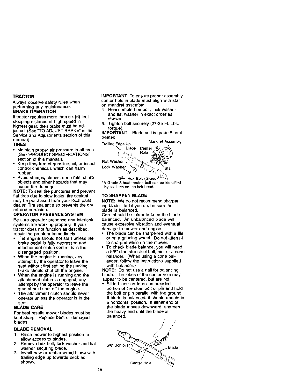
3. Install new or resharpened blade with
trailing edge up towards deck as
shown.
IMPORTANT: To ensure proper assembly,
center hole in blade must align with star
on mandrel assembly.
4. Reassemble hex bolt, lock washer
and flat washer in exact order as
shown.
5. Tighten boltsecurely (27-35 Ft. Lbs.
torque).
IMPORTANT: Blade bolt is grade 8 heat
treated.
Mandrel Assembly
Trailing e Up
Blade Center
Hole
Flat Washer
Lock Washer
TO SHARPEN BLADE
NOTE: We do not recommend sharpen-
ing blade - but if you do, be sure the
blade is balanced.
Care should be taken to keep the blade
balanced. An unbalanced blade will
cause excessive vibration and eventual
damage to mower and engine.
• The blade can be sharpened with a file
or on a grinding wheel. Do not attempt
to sharpen while on the mower.
• To check blade balance, you will need
a 5/8" diameter steel bolt, pin, or a cone
balancer. (When using a cone bal-
ancer, follow the instructions supplied
with balancer.)
NOTE: Do not use a nail for balancing
blade. The lobes of the center hole may
appear to be centered, but are not.
• Slide blade on to an unthreaded
portion of the steel bolt or pin and hold
the bolt or pin parallel with the ground.
If blade is balanced, it should remain in
a horizontal position. If either end of
the blade moves downward, sharpen
the heavy end until the blade is
balanced.
5/8" B_d e
Center Hole
/
_f-_ Hex Bolt
*A Grade 8 heattreated bolt canbe identified
bysix lines on the bolt head.
19
BATTERY
Your tractor has a battery charging system
which is sufficient for normal use. How-
ever, periodic charging of the battery with
an automotive charger will extend its life.
• Keep battery and terminals clean.
• Keep battery bolts tight.
• Keep small vent holes open.
• Recharge at 6-10 amperes for 1 hour.
NOTE: The original equipment battery on
your tractor is maintenance free. Do not
attempt to open or remove caps or covers.
Adding or checking level of electrolyte is
not necessary.
TO CLEAN BATTERY AND TERMINALS
Corrosion and dirt on the battery and
terminals can cause the battery to "leak"
power.
1. Open battery box door,
2. Disconnect BLACK battery cable first
then RED battery cable and remove
battery from tractor.
3. Rinse the battery with plain water and
dry.
4. Clean terminals and battery cable
ends with wire brush until bright.
5. Coat terminals with grease or petro-
leum jelly.
6. Reinstall battery (See "REPLACING
BATTERY" in the SERVICE AND
ADJUSTMENTS section of this
manual).
V-BELTS
Check V-beifs for deterioration and wear
after 100 hours of operation and replace
if necessary. The belts are not adjustable.
Replace belts if they begin to slip from
wear,
TRANBAXLE COOLING
The transmission fan and cooling fins
should be kept clean to assure proper
cooling.
Do not attempt to clean fan or transmis-
sion while engine is running or while the
transmission is hot. To prevent possible
damage to seals, do not use high
pressure water or steam to clean
transaxle.
• Inspect cooling fan to be sure fan
blades are intact end clean.
• inspect cooling fins for dirt, grass
clippings and other materials. To
prevent damage to seals, do not use
compressed air or high pressure
sprayer to clean cooling fins.
TRANSAXLE PUMP FLUID
The transaxle was sealed at the factory
and fluid maintenance is not required for
the life of the transaxle. Should the
transaxle ever leak or require servicing,
contact your nearest authorized service
center/department.
ENGINE
LUBRICATION
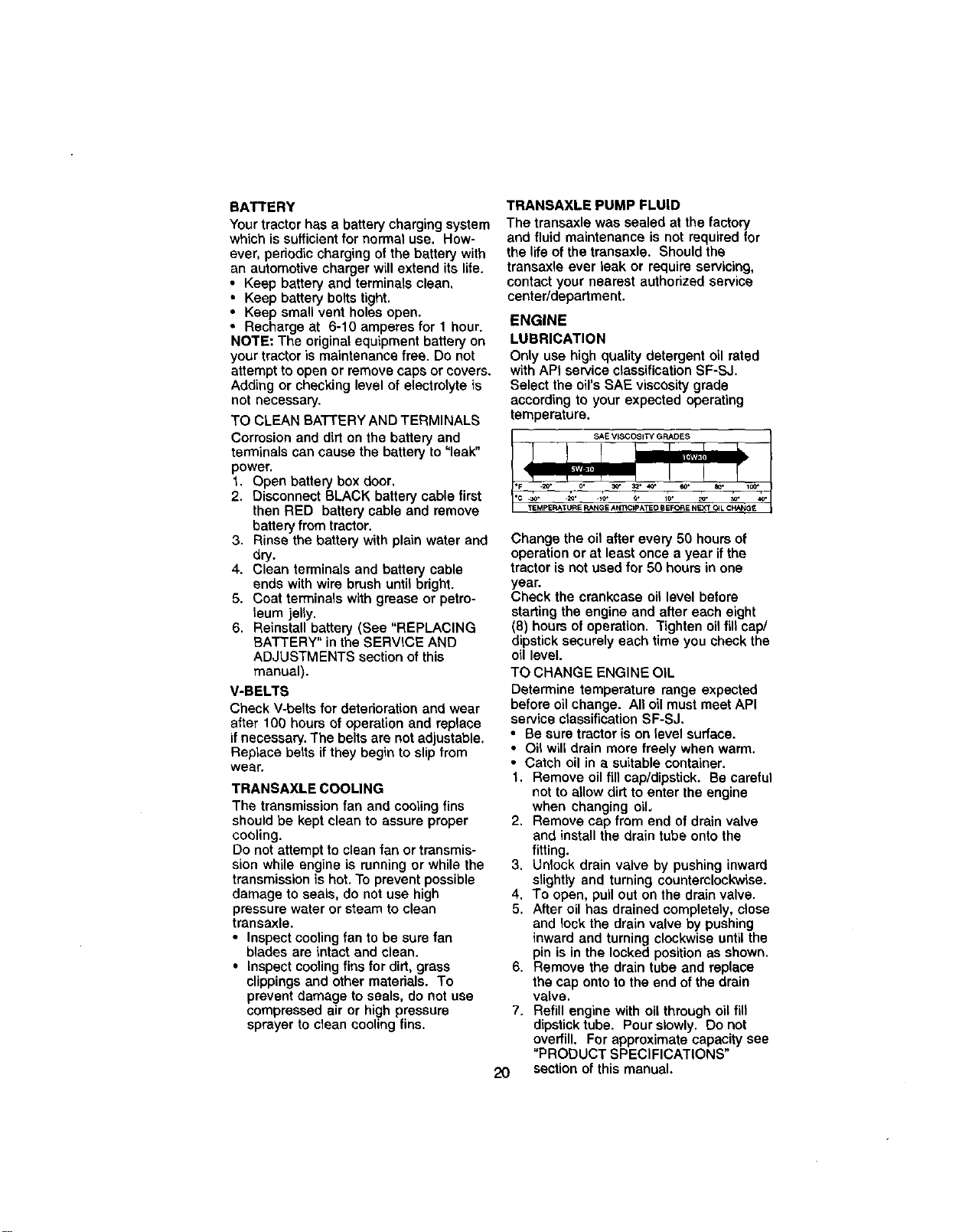
Only use high quality detergent oil rated
with APt service c_assification SF-SJ.
Select the oil's SAE viscosity grade
according to your expected operating
temperature.
Change the oil after every 50 hours of
operation or at least once a year if the
tractor is not used for 50 hours in one
year.
Check the crankcase oil level before
starting the engine and after each eight
(8) hours of operation. Tighten oil fill cap/
dipstick securely each time you check the
oil level.
TO CHANGE ENGINE OIL
Determine temperature range expected
before oil change. All oil must meet API
service classification SF-SJ.
• Be sure tractor is on level surface.
• Oi_will drain more freely when warm.
• Catch oil in a suitable container.
1. Remove oil fill cap/dipstick. Be careful
not to allow dirt to enter the engine
when changing oil.
2, Remove cap from end of drain valve
and install the drain tube onto the
fitting.
3. Unlock drain valve by pushing inward
slightly and turning counterclockwise.
4. To open, pull out on the drain valve.
5. After oil has drained completely, close
and lock the drain valve by pushing
inward and turning clockwise until the
pin is in the locked position as shown.
6. Remove the drain tube and replace
the cap onto to the end of the drain
valve.
7. Refill engine with oil through oil fin
dipstick tube. Pour slowly. Do not
overfill. For approximate capacity see
"PRODUCT SPECIFICATIONS"
section of this manual.
2O
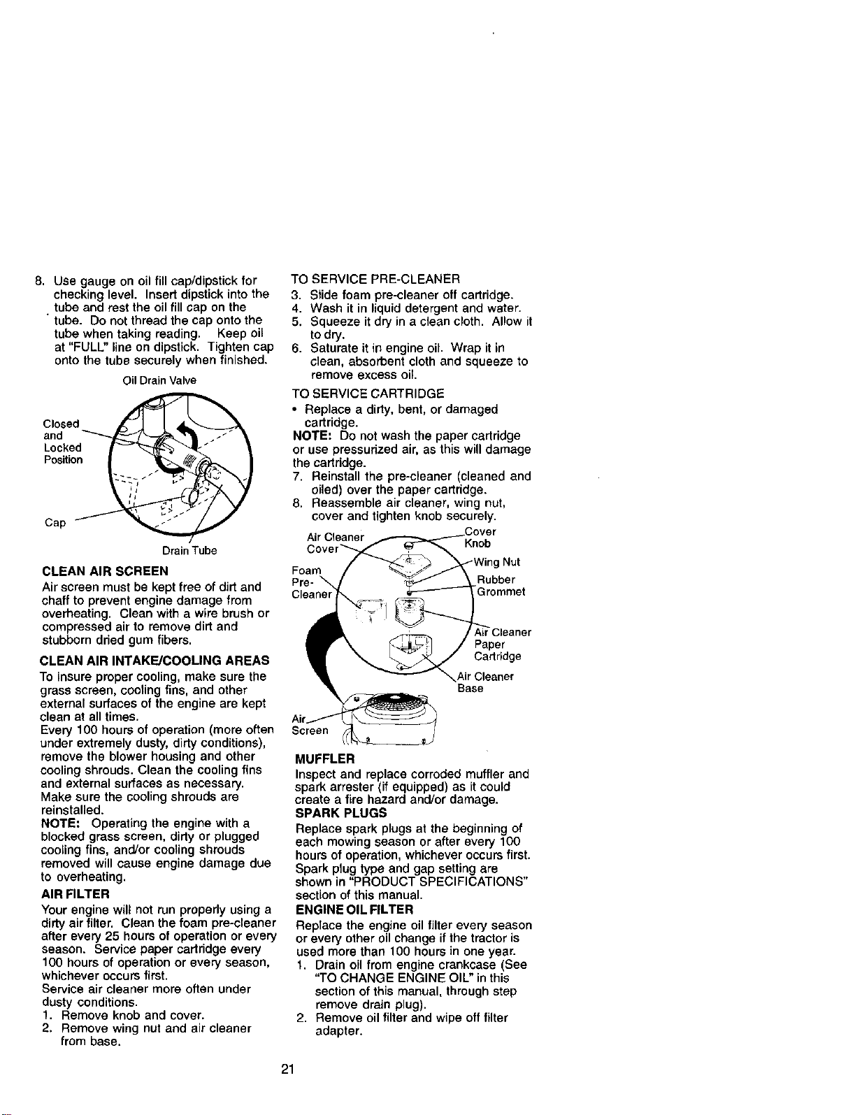
8. Use gauge on oil fill cap/dipstick for
checking level. Insert dipstick into the
• tube and rest the oil fill cap on the
tube. Do not thread the cap onto the
tube when taking reading• Keep oil
at "FULL" line on dipstick. Tighten cap
onto the tube securely when finished.
Oil DrainValve
Closed
and
Locked
Position
Cap
Drain Tube
CLEAN AIR SCREEN
Air screen must be kept free of dirt and
chaff to prevent engine damage from
overheating. Clean with a wire brush or
compressed air to remove dirt and
stubborn dried gum fibers.
CLEAN AIR INTAKE/COOLING AREAS
To insure proper cooling, make sure the
grass screen, cooling fins, and other
external surfaces of the engine are kept
clean at all times.
Every 100 hours of operation (more often
under extremely dusty, dirty conditions),
remove the blower housing and other
cooling shrouds. Clean the cooling fins
and external surfaces as necessary.
Make sure the cooling shrouds are
reinstalled.
NOTE: Operating the engine with a
blocked grass screen, dirty or plugged
cooling fins, and/or cooling shrouds
removed will cause engine damage due
to overheating.
AIR FILTER
Your engine wilt not run properly using a
dirty air filter. Clean the foam pre-cleaner
after every 25 hours of operation or every
season. Service paper cartridge every
100 hours of operation or every season,
whichever occurs first.
Service air cleaner more often under
dusty conditions.
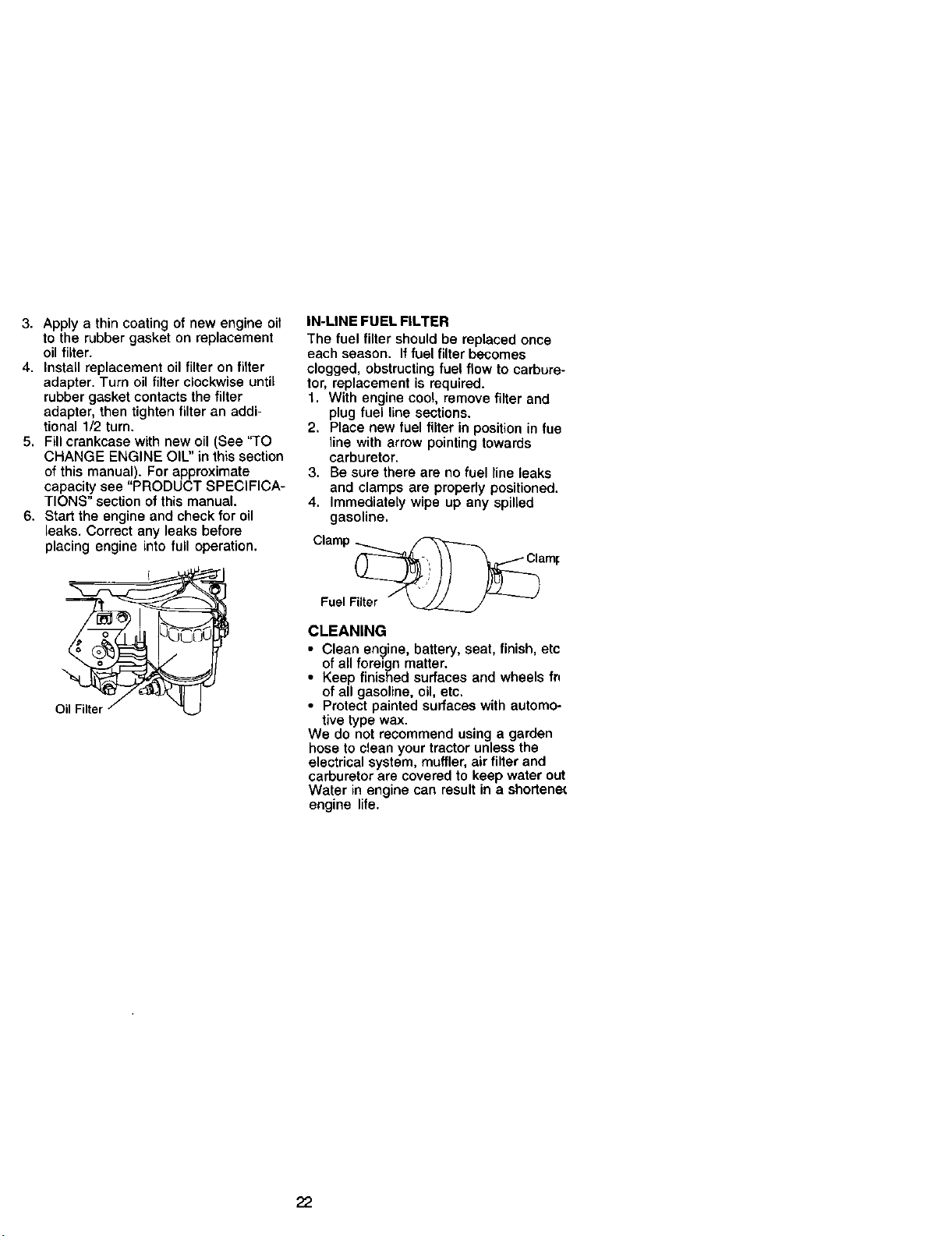
1. Remove knob and cover.
2. Remove wing nut and air cleaner
from base.
TO SERVICE PRE-CLEANER
3. Slide foam pre-cleaner off cartridge.
4. Wash it in liquid detergent and water.
5. Squeeze it dry in a clean cloth. Allow it
to dry.
6. Saturate it in engine oil. Wrap it in
clean, absorbent cloth and squeeze to
remove excess oil.
TO SERVICE CARTRIDGE
• Replace a dirty, bent, or damaged
cartridge.
NOTE= Do not wash the paper cartridge
or use pressurized air, as this will damage
the cartddge.
7. Reinstall the pre-cleaner (cleaned and
oiled) over the paper cartridge.
8. Reassemble air cleaner, wing nut,
cover and tighten knob securely.
Air Cleaner .Cover
Knob
Nut
Foam
Pre- Rubber
Paper
Cartridge
_ir Cleaner
Base
Screen
MUFFLER
Inspect and replace corroded muffler and
spark arrester (if equipped) as it could
create a fire hazard and/or damage.
SPARK PLUGS
Replace spark plugs at the beginning of
each mowing season or after every 100
hours of operation, whichever occurs first.
Spark plug type and gap setting are
shown in "PRODUCT SPECIFICATIONS"
section of this manual.
ENGINE OIL FILTER
Replace the engine oil filter every season
or every other oil change if the tractor is
used more than 100 hours in one year.
1. Drain oil from engine crankcase (See
"TO CHANGE ENGINE OIL" in this
section of this manual, through step
remove drain plug).
2. Remove oil filter and wipe offfilter
adapter.
21
3. Apply a thin coating of new engine oil
to the rubber gasket on replacement
oil filter.
4. Install replacement oil filter on filter
adapter. Turn oil filter clockwise until
rubber gasket contacts the filter
adapter, then tighten filter an addi-
tional 1/2 turn.
5. Fill crankcase with new oil (See "TO
CHANGE ENGINE OIU' in this section
of this manual). For approximate
capacity see "PRODUCT SPECIFICA-
TIONS" section of this manual.
6. Start the engine and check for oil
leaks. Correct any leaks before
placing engine into full operation.
IN-LINE FUEL FILTER
The fuel filter should be replaced once
each season. If fuel filter becomes
clogged, obstructing fuel flow to carbure-
tor, replacement is required.
1. With engine cool, remove filter and
plug fuel line sections.
2. Place new fuel filter in position in fue
line with arrow pointing towards
carburetor.
3. Be sure there are no fuel line leaks
and clamps are properly positioned.
4. Immediately wipe up any spilled
gasoline.
Clamp _ _
Fuel Filter _ --
CLEANING
• Clean engine, battery, seat, finish, etc
of all foreign matter.
• Keep finished surfaces and wheels fn
of all gasoline, oil, etc.
• Protect painted surfaces with automo-
tive type wax.
We do not recommend using a garden
hose to clean your tractor unless the
electrical system, muffler, air filter and
carburetor are covered to keep water out
Water in engine can result in a shortene(
engine life.
22
_CAUTION: BEFORE PERFORMING ANY SERVICE OR ADJUSTMENTS:
1. Depress clutch/brake pedal fully and set parking brake.
2. Place motion control lever in neutral (N) position,
3. Place attachment clutch in "DISENGAGED" position.
4. Turn ignition key "OFF" and remove key.
5. Make sure the blades and all moving parts have completely stopped.
6. Disconnect spark plug wire from spark plug and place wire where it cannot
come in contact with plug.
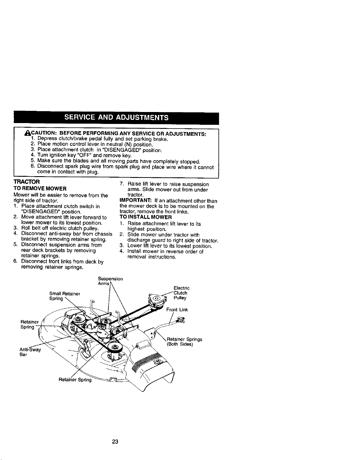
TRACTOR
TO REMOVE MOWER
Mower will be easier to remove from the
right side of tractor.
1, Place attachment clutch switch in
"DISENGAGED" position,
2, Move attachment lift lever forward to
lower mower to its lowest position,
3, Roll belt off electric clutch pulley.
4, Disconnect anti-sway bar from chassis
bracket by removing retainer spring.
5. Disconnect suspension arms from
rear deck brackets by removing
retainer springs,
6, Disconnect front links from deck by
removing retainer springs,
7. Raise lift lever to raise suspension
arms. Slide mower out from under
tractor.
IMPORTANT: If an attachment other than
the mower deck is to be mounted on the
tractor, remove the front links.
TO INSTALL MOWER
1. Raise attachment lift lever to its
highest position,
2. Slide mower under tractor with
discharge guard to right side of tractor,
3. Lower lift lever to its lowest position.
4. Install mower in reverse order of
removal instructions.
Suspens_n
Small Retainer
Spring
Electric
Pulley
Front Link
Retainer
Spring-
Bar
Retainer Springs
(Both Sides)
23
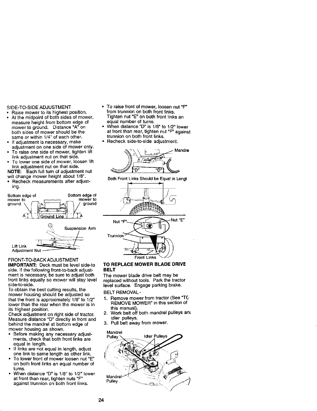
SIDE-TO-SIDE ADJUSTMENT
• Raise mower to its highest position.
• At the midpoint of both sides of mower,
measure height from bottom edge of
mower to ground. Distance "A" on
both sides of mower should be the
same or within 1/4" of each other.
• If adjustment is necessary, make
adjustment on one side of mower only.
• To raise one side of mower, tighten lift
link adjustment nut on that side.
• To lower one side of mower, loosen lift
link adjustment nut on that side.
NOTE: Each full turn of adjustment nut
will change mower height about 1/8".
• Recheck measurements after adjust-
ing.
Bottom edge of Bottomedgeof
mower to mowerto
ground _ ground
7A
Suspension Arm
_t_. /
Lift Link N_ut-----------'---'_" _ -
Adjustment
FRONT-TO-BACK ADJUSTMENT
IMPORTANT: Deck must be level side-to
side. If the following front-to-back adjust-
ment is necessary, be sure to adjust both
front links equally so mower will stay level
side-to-side.
To obtain the best cutting results, the
mower housing should be adjusted so
that the front is approximately 1/8" to 1/2"
lower than the rear when the mower is in
its highest position.
Check adjustment on right side of tractor.
Measure distance "D" directly in front and
behind the mandrel at bottom edge of
mower housing as shown.
• Before making any necessary adjust-
ments, check that both front links are
equal in length.
• If links are not equal in length, adjust
one link to same length as other link.
• To lower front of mower loosen nut "E"
on both front links an equal number of
turns.
• When distance "D" is 1/8" to 1/2" lower
at front than rear, tighten nuts "F"
against trunnion on both front links.
• To raise front of mower, loosen out "F"
from trunnion on both front links.
Tighten nut "E" on both front links an
equal number of turns.
• When distance "D" is 1/8" to 1/2" lower
at front than rear, tighten nut "F" against
trunnion on both front links.
• Recheck side-to-side adjustment.
_°_\ [,o ='_._ Mandre
Both Front LinksShould be Equal in Lengt
/
Nut ,,_ Nut "E"
Tmnnion_
TO REPLACE MOWER BLADE DRIVE
BELT
The mower blade drive belt may be
replaced without tools. Park the tractor
level surface. Engage parking brake.
BELT REMOVAL -
1. Remove mower from tractor (See "TC-
REMOVE MOWER" in this section of
this manual).
2. Work belt off both mandrel pulleys am
idler pulleys.
3. Pull belt away from mower.
24
BELT INSTALLATION -
4. Install new belt in reverse order of
• removal.
5. Make sure belt is in all pulley grooves
and inside all belt guides.
6. Install mower in reverse order of
removal instructions.
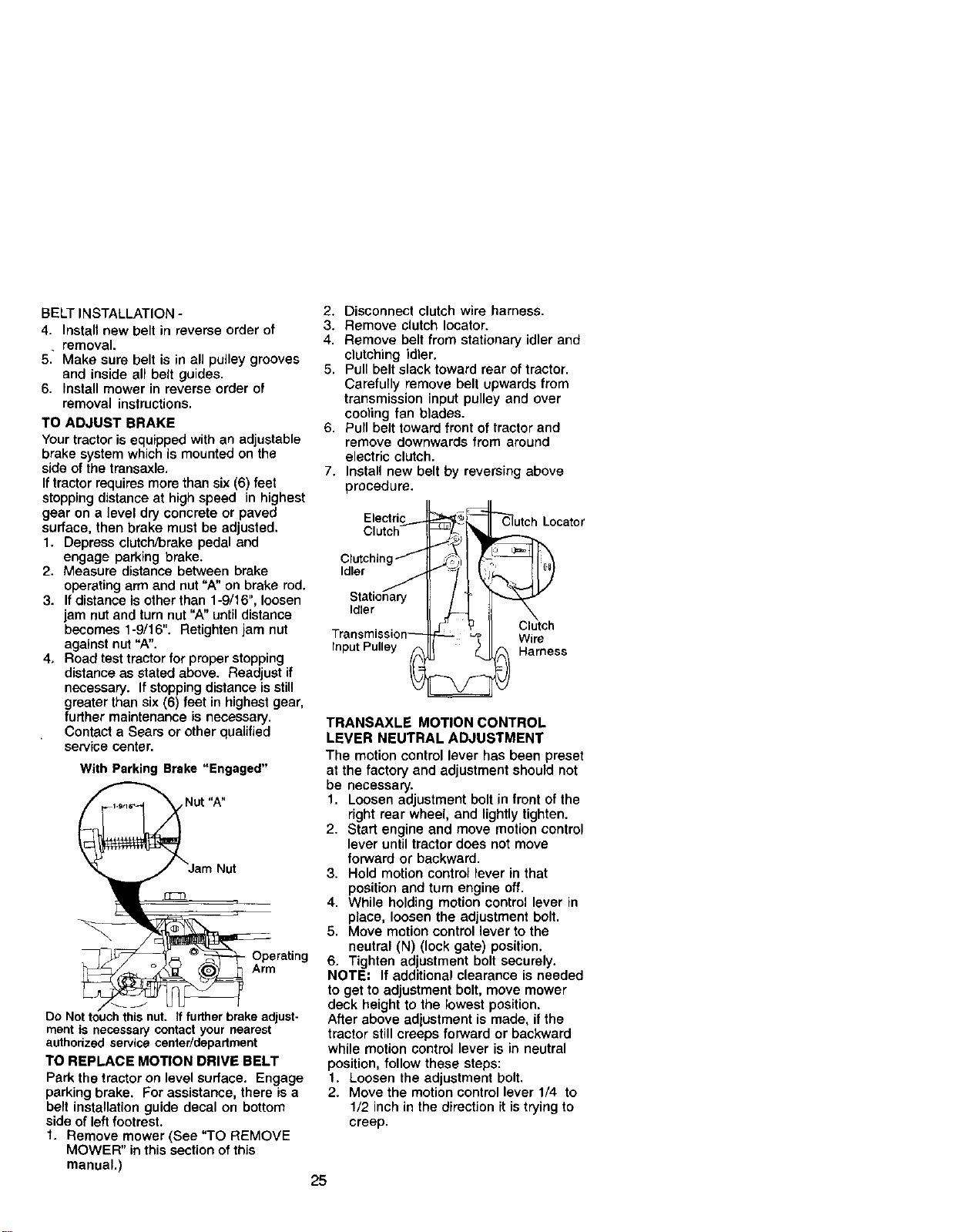
TO ADJUST BRAKE
Your tractor is equipped with an adjustable
brake system which is mounted on the
side of the transaxle.
If tractor requires more than six (6) feet
stopping distance at high speed in highest
gear on a level dry concrete or paved
surface, then brake must be adjusted.
1. Depress clutch/brake pedal and
engage parking brake.
2. Measure distance between brake
operating arm and nut "A" on brake rod.
3. Ifdistance is other than 1-9/16", loosen
jam nut and turn nut "A" until distance
becomes 1-9/16". Retighten jam nut
against nut "A".
4, Road test tractor for proper stopping
distance as stated above. Readjust if
necessary. If stopping distance is still
greater than six (6) feet in highest gear,
furfher maintenance is necessary.
Contact a Sears or other qualified
service center.
With Parking Brake "Engaged"
Nut "A"
- Operating
Arm
DONo nut. iffurther brake adjust-
ment is necessarycontactyour nearest
authodzed servicecenter/department
TO REPLACE MOTION DRIVE BELT
Park the tractor on level surface. Engage
parking brake. For assistance, there is a
belt installation guide decal on bottom
side of left footrest.
1. Remove mower (See "TO REMOVE
MOWER" in this section of this
manual.)
2. Disconnect clutch wire harness.
3. Remove clutch Iocator.
4. Remove belt from stationary idler and
clutching idler.
5. Pull belt slack toward rear of tractor.
Carefully remove belt upwards from
transmission input pulley and over
cooting fan blades.
6. Pull belt toward front of tractor and
remove downwards from around
electric clutch.
7. Install new belt by reversing above
procedure.
Electri
Locater
Clutchin
Idler
Idler
Wire
Input Pulley Harness
TRANSAXLE MOTION CONTROL
LEVER NEUTRAL ADJUSTMENT
The motion control lever has been preset
at the factory and adjustment should not
be necessary.
1. Loosen adjustment bolt in front of the
right rear wheel, end lightly tighten.
2. Start engine and move motion control
lever until tractor does not move
forward or backward.
3. Hold motion control lever in that
position and turn engine off.
4. While holding motion control lever in
place, loosen the adjustment bolt.
5. Move motion control lever to the
neutral (N) (lock gate) position.
6. Tighten adjustment bolt securely.
NOTE: If additional clearance is needed
to get to adjustment bolt, move mower
deck height to the lowest position,
After above adjustment is made, if the
tractor still creeps forward or backward
while motion control lever is in neutral
position, follow these steps:
1, Loosen the adjustment bolt,
2. Move the motion control lever 1/4 to
1/2 inch in the direction it istrying to
creep.
25
3. Tighten adjustment bolt securely.
4. Start engine and test.
5. If tractor still creeps, repeat above
steps until satisfied.
Motion Control
Neutral Lock Gate
Lever
TRANSMISSION REMOVAL/REPLACE-
MENT
Should your transmission require
removal for service or replacement, it
should be purged after reinstallation and
before operating the tractor. See
"PURGE TRANSMISSION" in the
Operation section of this manual.
TO ADJUST STEERING WHEEL ALIGN-
MENT
If steedng wheel croeebam are not
horizontal (left to right) when wheels are
positioned straight forward, remove
steedn_ wheel and reassemble per
instructions in the Assembly section of
this manual.
FRONT WHEEL TOE-IN/CAMBER
The front wheel toe-in and camber are
not adjustable on your tractor. If damage
has occurred to affect the front wheel toe-
in or camber, contact a Sears or other
qualified service center.
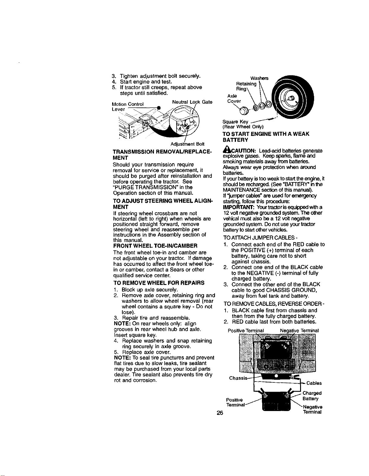
TO REMOVE WHEEL FOR REPAIRS
1. Block up axle securely.
2. Remove axle cover, retaining ring and
washers to allow wheel removal (rear
wheel contains a square key - Do not
lose).
3. Repair tire and reassemble.
NOTE: On rear wheels only: align
grooves in rear wheel hub and axle.
Insert square key.
4. Replace washers and snap retaining
ring securely in axle groove.
5. Replace axle cover.
NOTE: To seal tire punctures and prevent
flat tires due to slow leaks, tire sealant
may be purchased from your local parts
dealer. Tire sealant also prevents tire dry
rot and corrosion.
Washers
Retaining_ f_'_
Ring\ I\ _'_"_'_'_
Axle \ I \ II/1{_ llll
Square Key
(Rear Wheel Only)
TO START ENGINE WITH A WEAK
BATTERY
z't
4UICAUTION: Lead-acid batteries generate
explosive gases. Keep sparks,flame and
smoking materials away from batteries.
Always wear eye protection when mound
batter;_=s.
Ifyour battery istoo weak to start the engine, it
should be recharged. (See "BATFERY"in the
MAINTENANCE section of this manual).
ff"jumper cables" are used for emergency
starting, follow this procedure:
IMPORTANT: Yourtractor is equi_ with a
12volt negative grounded system.The other
vehical must also be a 12 volt negative
grounded system. Do not use your tractor
battery to start other vehicles.
TO ATI'ACH JUMPER CABLES -
1. Connect each end of the RED cable to
the POSITIVE (+) terminal of each
battery, taking care not to short
against chassis.
2. Connect one end of the BLACK cable
to the NEGATIVE (-) terminal of fully
charged battery.
3. Connect the other end of the BLACK
cable to good CHASSIS GROUND,
away from fuel tank and battery.
TO REMOVE CABLES, REVERSE ORDER -
1. BLACK cable first from chassis and
then from the fully charged battery.
2. RED cable last from both batteries.
Positive Terminal Negative Terminal
Cables
Positive Battery
26 Terminal
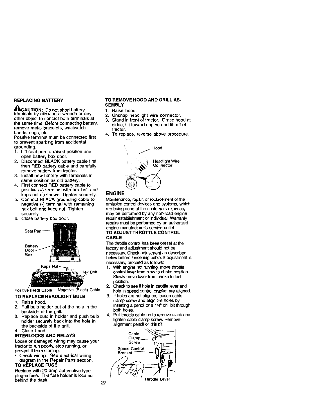
REPLACINGBATTERY
_IkCAUT!ON: Do not short battery
terminais Dy allowing a wrench or any
other object to contact both terminals at
the same time, Before connecting battery,
remove metal bracelets, wristwatch
bands, rings, etc.
Positive terminal must be connected first
to prevent sparking from accidental
grounding.
1. Lift seat pan to raised position and
open battery box door.
2. Disconnect BLACK battery cable first
then RED battery cable and carefully
remove battery from tractor.
3. Install new battery with terminals in
same position as old battery.
4, First connect RED battery cable to
positive (+) terminal with hex bolt and
keps nut as shown. Tighten securely.
5. Connect BLACK grounding cable to
negative (-) terminal with remaining
hex bolt and keps nut, Tighten
securely.
6. Close battery box door.
Seat PanI
Battery _.,,-"_!_,
Ooor_ F_II_
Box __
Keps
Hex Belt
Positive(Red)Cable Negative (Black) Cable
TO REPLACE HEADLIGHT BULB
1. Raise hood.
2. Pull bulb holder out of the hole in the
backside of the grill.
3. Replace bulb in holder and push bulb
holder securely back into the hole in
the backside of the grill.
4, Close hood,
INTERLOCKS AND RELAYS
Loose or damaged wiring may cause your
tractor to run poorly,stop running, or
prevent it from starting.
• Check widng. See electrical wiring
diagram in the Repair Parts section.
TO REPLACE FUSE
Replace with 20 amp automotive-type
plug-in fuse, The fuse holder is located
behind the dash.
TO REMOVE HOOD AND GRILL AS-
SEMBLY
1, Raise hood.
2, Unsnap headlight wire connecter.
3, Stand in front oftractor. Grasp hood at
sides, tilt toward engine and lift off of
tractor.
4. To replace, reverse above procedure.
,, _ Hood
i _ Headlight Wire
._) Connector
ENGINE
Maintenance, repair,or replacement ofthe
emission controldevicas and systems, which
are being done at the customers expense,
may be performed by any non-roadengine
repairestablishmentor individual. Warranty
repairs must be performed by an authorized
engine manufacture¢s service outlet.
TO ADJUST THROTTLE CONTROL
CABLE
The throttlecontrolhas been preset at the
factoryand adjustmentshould not be
necessary.Check adjustmentas described
belowbefore loosening cable. Ifadjustment is
necessary, proceed as follows:
1. With engine not running, move throttle
controlleverfromslow to choke position.
Slowlymove leverfromchoke tofast
position.
2. Check tosee if holeinthrottlelever and
holein speed control bracket are aligned.
3. If holesare not aligned, loosencable
clamp screw and align the holesby
insertinga pencil ora 1/4" drillbitthrough
beth holes.
4, Pullthrottlecable upto remove slack and
tightencable clamp screw, Remove
alignment pencil or drillbit.
Cable _
Clamp_.__.__L:_['_
Screw _----]
Speed Coontrol _'_/_ I
_Bracket
27
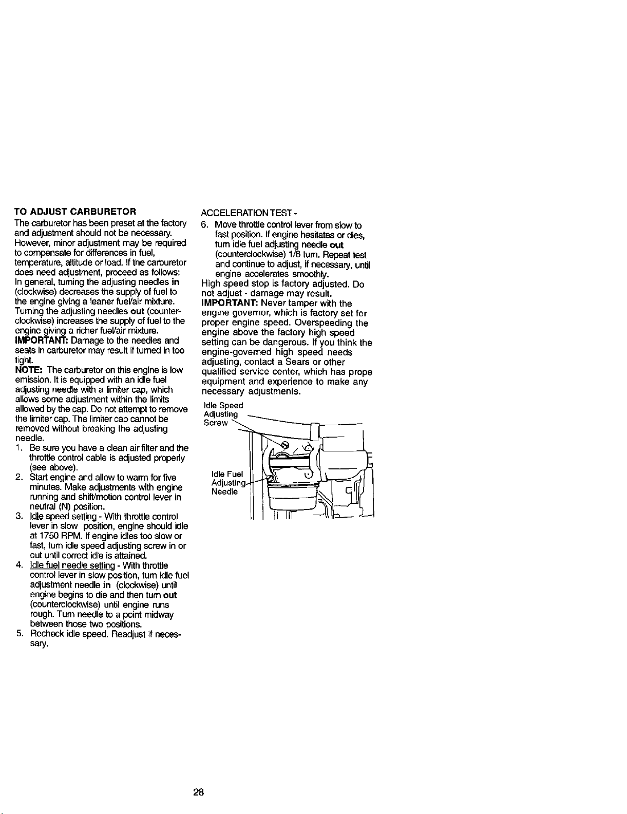
TO ADJUST CARBURETOR
The carburetor has been preset at the factory
and adjustment should not be necessary.
However, minor adjustment may be required
to compensate for differences in fuel,
temperature, altitude or lead. Ifthe carburetor
does need adjustment, proceed as follows:
In general, turning the adjusting needles in
(clockwise) decreases the supply of fuel to
the engine giving a leaner fuel/air mixture.
Tumiog the adjusting needles out (counter-
clockwise) increases the supply of fuel to the
engine giving a richer fueVair mixture.
IMPORTANT: Damage to the needles and
seats in carburetor may result ifturned in too
tight.
NOTE: The carburetor on this engine is low
emission. It is equipped with an idle fuel
adjusting needle with a limiter cap, which
allows some adjustment within the limits
allowed by the cap. Do not attempt to remove
the limiter cap. The limber cap cannot be
removed without breaking the adjusting
needle.
1. Be sere you have a clean air filter and the
throttle control cable is adjusted properly
(see above).
2. Start engine and allow to warm for five
minutes. Make adjustments with engine
running and shift/motion control lever in
neutral (N) position.
3. Idle seeed setting - With throttle control
lever in slow position, engine should idle
at 1750 RPM. Ifengine idles too slow or
fast, turn idle speed adjusting screwin or
out until correct idle is attained.
4. idle fuel needle setting - With threttle
control lever in slow position, turn idle fuel
adjustment needle in (clockwise) until
engine begins to die and then turn out
(counterclockwise) until engine runs
rough. Turn needle to a point midway
between those two positions.
5. Recheck idle speed. Readjust if neces-
sery.
ACCELERATION TEST-
6. Move threttle control lever fromslow to
fast position. Ifengine hesitates or dies,
turn idle fuel adjusting needle out
(counterclockwise) 1/8 rum. Repeat test
and continue to adjust, ifnecessary, until
engine accelerates smoothly.
High speed stop is factory adjusted. Do
not adjust - damage may result.
IMPORTANT: Never tamper with the
engine governor, which is factory set for
proper engine speed. Overspeeding the
engine above the factory high speed
setting can be dangerous. If you think the
engine-governed high speed needs
adjusting, contact a Sears or other
qualified service center, which has probe
equipment and experience to make any
necessary adjustments.
Idle Speed
Adjusting --...__...._
Screw _
Needle
28
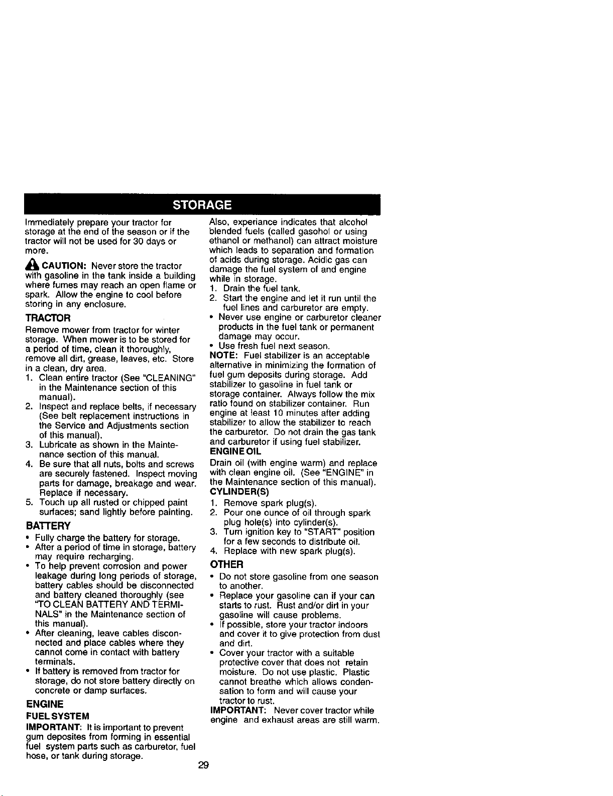
Immediately prepare your tractor for
storage at the end of the season or if the
tractor will not be used for 30 days or
more.
,_ CAUTION= Never store the tractor
with gasoline in the tank inside a building
where fumes may reach an open flame or
spark. Allow the engine to cool before
storing in any enclosure.
TRACTOR
Remove mower from tractor for winter
storage. When mower is to be stored for
a period of time, clean it thoroughly,
remove all dirt, grease, leaves, etc. Store
in a clean, dry area.
1. Clean entire tractor (See "CLEANING"
in the Maintenance section of this
manual).
2. Inspect and replace belts, if necessary
(See belt replacement instructions in
the Service and Adjustments section
of this manual).
3. Lubricate as shown in the Mainte-
nance section of this manual.
4. Be sure that all nuts, bolts end screws
are securely fastened. Inspect moving
parts for damage, breakage and wear.
Replace if necessary.
5. Touch up all rusted or chipped paint
surfaces; sand lightly before painting.
BA'rrERY
• Fully charge the battery for storage.
• After a period of time in storage, battery
may require recharging.
• To help prevent corrosion and power
leakage during long periods of storage,
battery cables should be disconnected
and battery cleaned thoroughly (see
"TO CLEAN BATTERY AND TERMI-
NALS" in the Maintenance section of
this manual).
• After cleaning, leave cables discon-
nected and place cables where they
cannot come in contact with battery
terminals.
• If battery is removed from tractor for
storage, do not store battery directly on
concrete or damp surfaces.
ENGINE
FUEL SYSTEM
IMPORTANT: Itis important to prevent
gum depositas from forming in essential
fuel system parts such as carburetor, fuel
hose, or tank during storage.
Also, experiance indicates that alcohol
blended fuels (called gasohol or using
ethanol or methanol) can attract moisture
which leads to separation end formation
of acids during storage. Acidic gas can
damage the fuel system of and engine
while in storage.
1. Drain the fuel tank.
2. Starf the engine and let it run until the
fuel lines and carburetor are empty.
• Never use engine or carburetor cleaner
products in the fuel tank or permanent
damage may occur.
• Use fresh fuel next season.
NOTE: Fuel stabilizer is an acceptable
alternative in minimizing the formation of
fuel gum deposits during storage. Add
stabilizer to gasoline in fuel tank or
storage container. Always follow the mix
ratio found on stabilizer container. Run
engine at least 10 minutes after adding
stabilizer to allow the stabilizer to reach
the carburetor. Do not drain the gas tank
and carburetor if using fuel stabilizer.
ENGINEOIL
Drain oil (with engine warm) and replace
with clean engine oil. (See "ENGINE" in
the Maintenance section of this manual).
CYLINDER(S)
1. Remove spark plug(s).
2. Pour one ounce of oil through spark
plug hole(s) into cylinder(s).
3. Turn ignition key to "START" position
for a few seconds to distribute oil.
4. Replace with new spark plug(s).
OTHER
• Do not store gasoline from one season
to another.
• Replace your gasoline can if your can
starts to rust. Rust and/or dirt in your
gasoline will cause problems.
• If possible, store your tractor indoors
and cover it to give protection from dust
and dirt.
• Cover your tractor with a suitable
protective cover that does not retain
moisture. Do not use plastic. Plastic
cannot breathe which allows conden-
sation to form and will cause your
tractor to rust.
IMPORTANT: Never cover tractor while
engine and exhaust areas are still warm.
29
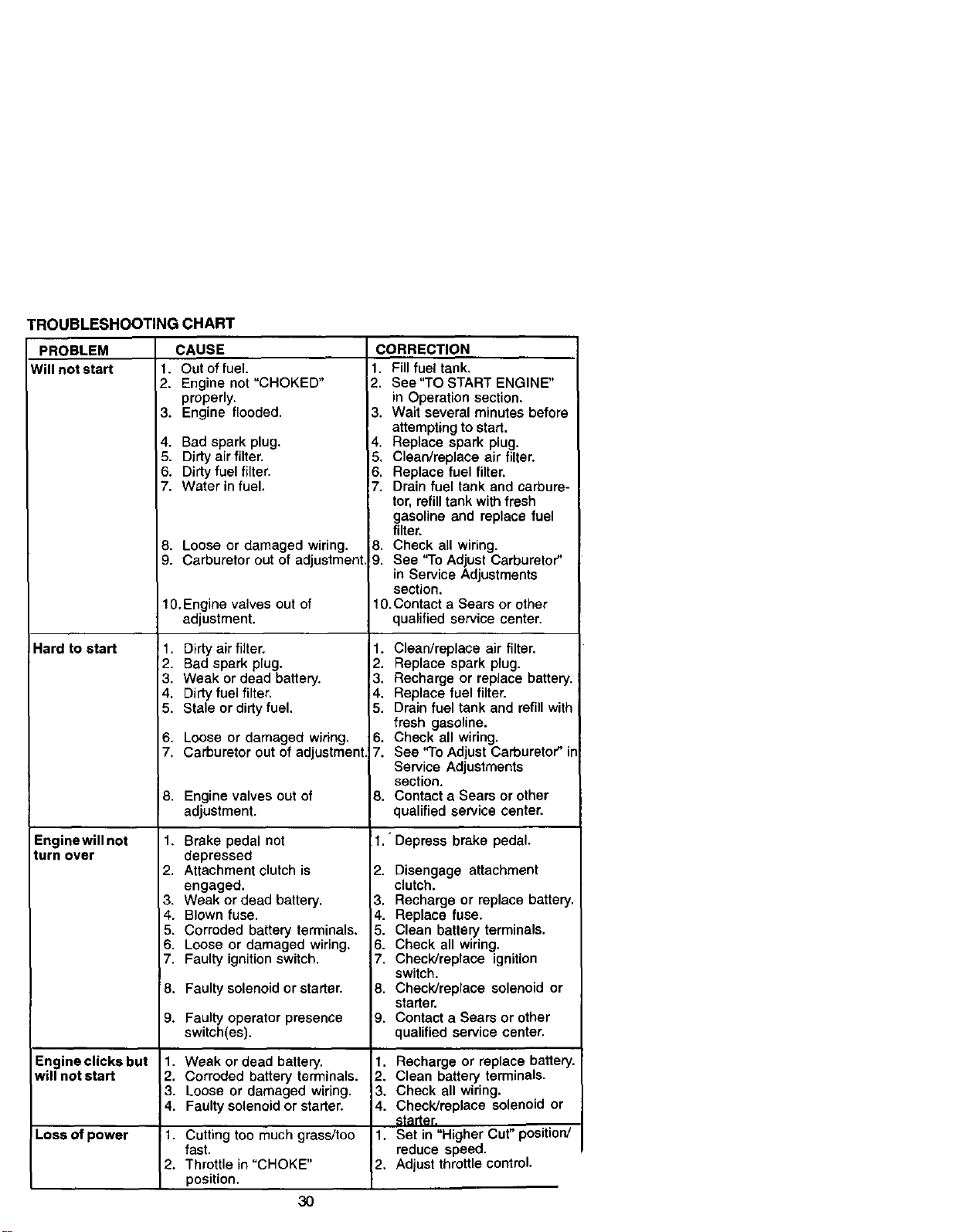
TROUBLESHOOTING CHART
PROBLEM
Will not start
CAUSE
1. Out of fuel.
2. Engine not "CHOKED"
properly.
3. Engine flooded.
Hard to start
Enginewill not
turn over
Engine clicks but
will not start
!Lossof power
4. Bad spark plug.
5. Dirty air filter,
6. Dirty fuel filter.
7. Water in fuel.
8. Loose or damaged wiring.
9. Carburetor out of adjustment
10.Engine valves out of
adjustment.
1. Dirty air filter,
2. Bad spark plug,
3. Weak or dead battery.
4. Dirtyfuel filter.
5. Stale or dirty fuel.
6. Loose or damaged wiring.
7. Carburetor out of adjustment
8. Engine valves out of
adjustment.
1. Brake pedal not
depressed
2. Attachment clutch is
engaged.
3. Weak or dead battery.
4. Blown fuse.
5. Corroded battery terminals.
6. Loose or damaged wiring.
7. Faulty ignition switch.
8. Faulty solenoid or starter.
9. Faulty operator presence
switch(es).
1. Weak or dead battery.
2. Corroded battery terminals.
3. Loose or damaged wiring.
4. Faulty solenoid or starter.
1. Cutting too much grass/too
fast.
2. Throttle in "CHOKE"
position.
CORRECTION
1. Fill fuel tank.
2. See "TO START ENGINE"
in Operation section.
3. Wait several minutes before
attempting to start.
4. Replace spark plug.
5. Clean/replace air filter.
6. Replace fuel filter.
7. Drain fuel tank and carbure-
tor, refill tank with fresh
gasoline and replace fuel
filter.
8. Check all wiring.
9. See "To Adjust Carburetor"
in Service Adjustments
section.
10.Contact a Sears or other
qualified service center.
1. Clean/replace air filter.
2. Replace spark plug.
_3. Recharge or replace battery.
4 Replace fuel filter•
5. Drain fuel tank and refill with
fresh gasoline.
6. Check all wiring.
7. See "To Adjust Carburetor" ir
Service Adjustments
section.
8. Contact a Sears or other
qualified service center.
1. Depress brake pedal.
2. Disengage attachment
clutch.
3. Recharge or replace battery.
4. Replace fuse.
5. Clean battery terminals.
6. Check all wiring.
7. Check/replace ignition
switch.
8. Check/replace solenoid or
starter.
9. Contact a Sears or other
qualified service center.
I. Recharge or replace battery.
2. Clean battery terminals.
3. Check all wiring.
4. Check/replace solenoid or
starter.
1. Set in "Higher Cut" position/
reduce speed.
2. Adjust throttle control.
3O
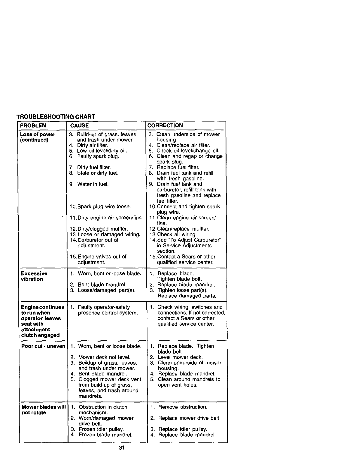
TROUBLESHOOTINGCHART
CAUSE CORRECTIONPROBLEM
Loss of power
continued)
Excessive
vibration
Engine continues
to run when
operator leaves
seat with
attachment
clutch engaged
Poorcut-uneven
Mower blades will
not rotate
3. Build-up of grass, leaves
and trash under mower.
4. Dirty air filter.
5. Low oil leveVdirty oil.
6. Faulty spark plug.
7. Dirty fuel filter.
8. Stale or dirty fuel.
9. Water in fuel.
10. Spark plug wire loose.
11. Dirty engine air screen/fins.
12. Dirty/clogged muffler.
t3. Loose or damaged wiring.
14.Carburetor out of
adjustment.
15.Engine valves out of
adjustment.
1. Worn, bent or loose blade.
2. Bent blade mandrel.
3. Loose/damaged part(s).
1. Faulty operator-safety
presence control system.
1. Worn, bent or loose blade.
2. Mower deck not level.
3. Buildup of grass, leaves,
and trash under mower.
4. Bent blade mandrel.
5. Clogged mower deck vent
from build-up of grass,
leaves, and trash around
mandrels.
1. Obstruction in clutch
mechanism.
2. Worn/damaged mower
drive belt,
3. Frozen idler pulley.
4. Frozen blade mandrel.
3. Clean underside of mower
housing.
4. Clean/replace air filter.
5. Check oil level/change oil
6. Clean and regap or change
spark plug.
7. Replace fuel filler.
8. Drain fuel tank and refill
with fresh gasoline.
9. Drain fuel tank and
carburetor, refill tank with
fresh gasoline and replace
fuel filter.
lO.Connect and tighten spark
plug wire.
11 .Clean engine air screen/
fins.
12.Clean/replace muffler.
13.Check all wiring.
14.See "To Adjust Carburetor"
in Service Adjustments
section.
15.Contact a Sears or other
qualified service center.
1. Replace blade.
Tighten blade bolt.
2. Replace blade mandrel.
3. Tighten loose part(s).
Replace damaged parts.
1. Check wiring, switches and
connections. If not corrected
contact a Sears or other
qualified service center.
1. Replace blade. Tighten
blade bolt.
2. Level mower deck.
3. Clean underside of mower
housing.
4. Replace blade mandrel.
5. Clean around mandrels to
open vent holes.
1. Remove obstruction.
2. Replace mower drive belt.
3. Replace idler pulley.
4. Replace blade mandrel.
31
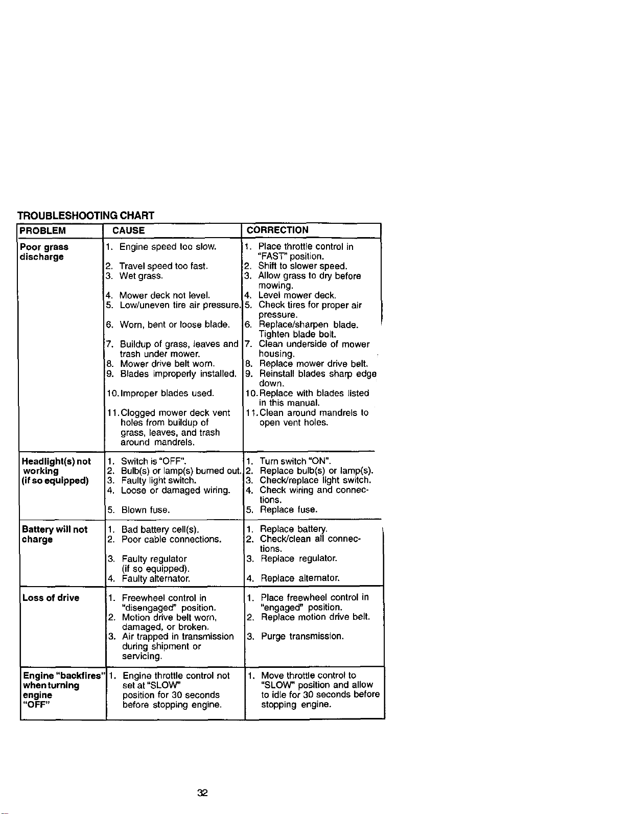
PROBLEM
Poor grass
discharge
TROUBLESHOOTING CHART
CAUSE
1. Engine speed too slow.
2. Travel speed too fast.
Headlight(s) not
working
(if so equipped)
Battery will not
charge
Loss of drive
3. Wet grass.
4. Mower deck not level.
5. Low/uneven tire air pressure.
6. Worn, bent or loose blade.
7. Buildup of grass, leaves and
trash under mower.
8. Mower drive belt worn.
9. Blades improperly installed.
10.Improper blades used.
11. Clogged mower deck vent
holes from buildup of
grass, leaves, and trash
around mandrels.
1. Switch is "OFF".
2. Bulb(s) or lamp(s) burned out.
3. Faulty light switch.
4. Loose or damaged wiring.
5. Blown fuse.
1. Bad battery cell(s).
2. Poor cable connections.
3. Faulty regulator
(if so equipped).
4. Faulty alternator.
11. Freewheel control in
"disengaged" position.
2. Motion drive belt worn,
damaged, or broken,
3. Air trapped in transmission
during shipment or
servicing.
CORRECTION
1. Place throttle control in
"FAST" position.
2. Shift to slower speed.
3. Allow grass to dry before
mowing.
4. Level mower deck.
5. Check tires for proper air
pressure.
6. Replace/sharpen blade.
Tighten blade bolt.
7. Clean underside of mower
housing.
8. Replace mower drive belt.
9. Reinstall blades sharp edge
down.
10. Replace with blades listed
in this manual.
11.Clean around mandrels to
open vent holes.
1. Turn switch "ON".
2. Replace bulb(s) or lamp(s).
3. Check/replace light switch.
4. Check wiring and connec-
tions.
5. Replace fuse.
1. Replace battery.
2. Check/clean all connec-
tions.
3. Replace regulator.
4. Replace alternator.
1. Place freewheel control in
"engaged" position.
2, Replace motion drive belt.
3. Purge transmission.
Engine "backfires' 1. Engine throttle control not 1. Move throttle control to
whenturning set at "SLOW" "SLOW" position and allow
engine position for 30 seconds to idle for 30 seconds before
"OFF" before stopping engine, stopping engine.
32
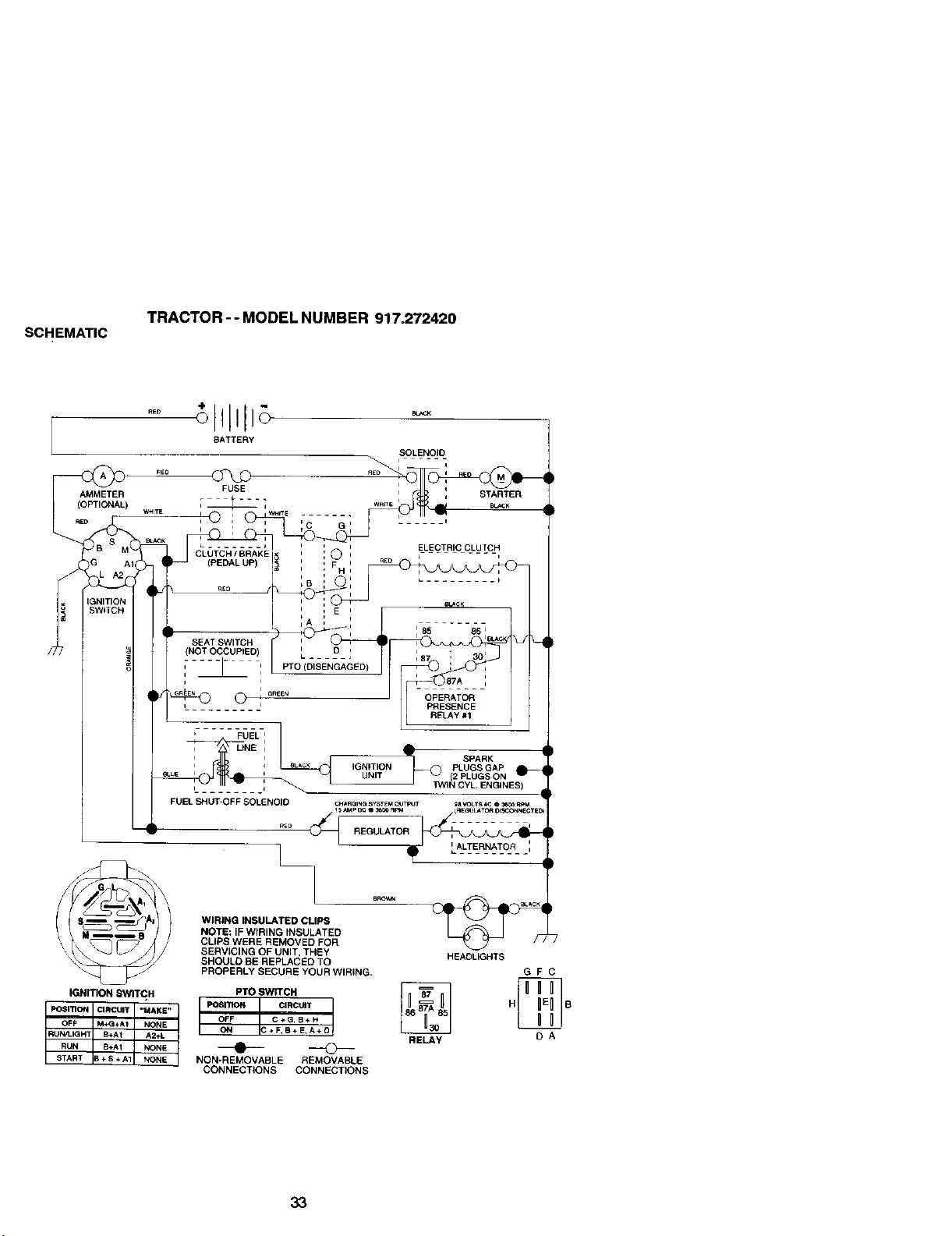
SCHEMATIC
TRACTOR - - MODEL NUMBER 917.272420
"°
BATTERY
SOLENOID
AMMETER _ USE _ _ ' , STARTER
/ ! O ' F_ =wHrrE , ! '_' II
"° : i , :c _: -- '
i i ELECTRIC CLUTCH
/'_ - '_ I #L_-.;_,_;,_L-,, O, ,_ -...... ,
' ', E '
IA: :
i- l t
/77 • 9_:
SPARK
(2 PLUGS ON
nnNIN CYL ENGINES I
FUEL SHUT-OFF__SOLENOID CHAA_R_iNocG SoYSTE3600MR0_ IT _RSEGV_uLTLAST__I_B000,_N_O_TE_
_z:::z_ _ NOTE: IF WIRING INSULATED
t,l,-_sj) CL,PSWEREREMOVED,OR_I'_
", t\_ _J J _ _ /Jl SERVICING OF UNIT, THEY H EAO_GHTS
_._ SHOULD BE REPLACED TO
_/ PROPERLY SECURE YOUR WIRING G F C
IGNITION SWITCH PTO SWITCH _
PO$mON CIRCUIT _MAKE" POSITION CIRCUIT H B
OFF M÷Q+AI NONE OFF C ÷ Q. B+ H
RUNA-IGHT B+At A2+L ON C÷F'B+ E'A÷O RELAy O A
RUN B+AI NONE _STAR'r B+B+AI NONE NON-REMOVABLE REMOVABLE
CONNECTIONS CONNECTIONS
33
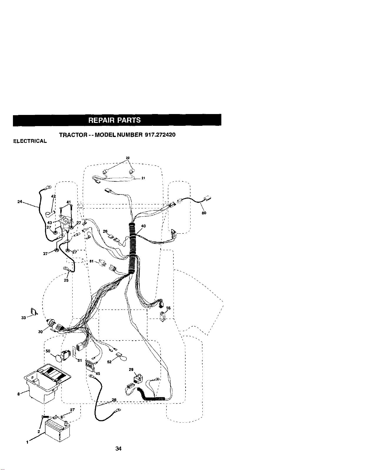
ELECTRICAL
TRACTOR -- MODEL NUMBER 917.272420
22
S
//
iI
I
I t
41
26
i
i
_ 25
4O
34
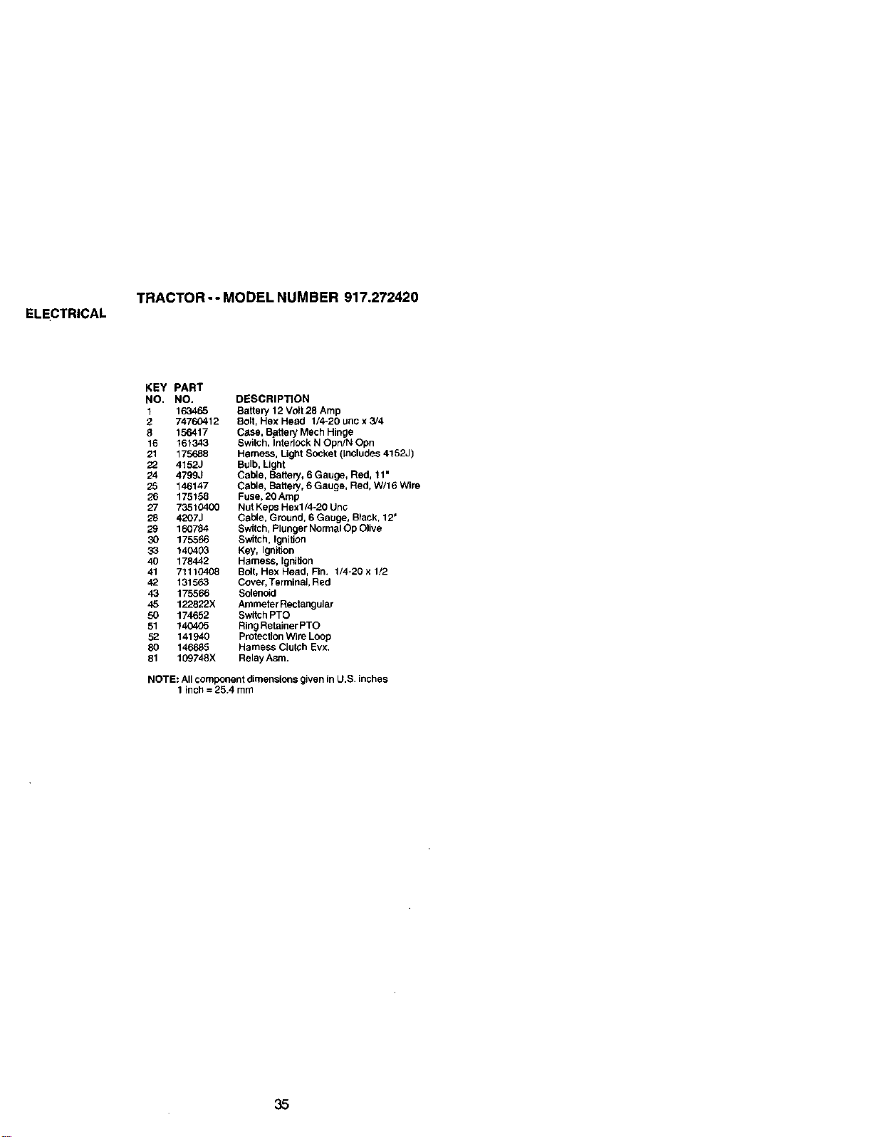
ELECTRICAL
TRACTOR -- MODEL NUMBER 917.272420
KEY PART
NO, NO. DESCRIPTION
1 163465 Battery 12 Volt 28 Amp
2 74760412 Bolt, Hex Head 1/4-20 unc x 3J4
8 156417 Case, Battery Mech Hinge
16 161343 Switch, Interlock N Opn/N Opn
21 175688 Harness, Light Socket (Includes 4152J)
22 4152J Bulb, Light
24 4799J Cable, Battery, 6 Gauge, Red, 11 •
25 146147 Cab4e, Battery, 6 Gauge, Red, W/16 Wire
26 175158 Fuse, 20Amp
27 73510400 Nut Keps Hexl/4-20 Unc
28 4207J Cable, Ground, 6 Gauge, Black, 12 •
29 160784 Switch, Plunger Normal Op Olive
30 175566 Switch, Ignition
33 140403 Key, Ignition
40 178442 Harness, Ignition
41 71110408 Boll, Hex Head, Fin, 1/4-20 x 1/2
42 131563 Cover, Terminal, Red
43 175566 Solenoid
45 122822X Ammeter Rectangular
50 174652 Switch PTO
51 140405 Ring Retainer PTO
52 141940 Protection Wire Loop
80 146685 Hamess Clutch Evx.
81 109748X Relay Asm.
NOTE: All component dimensions given in U.S. inches
1 inch = 25.4 mm
35
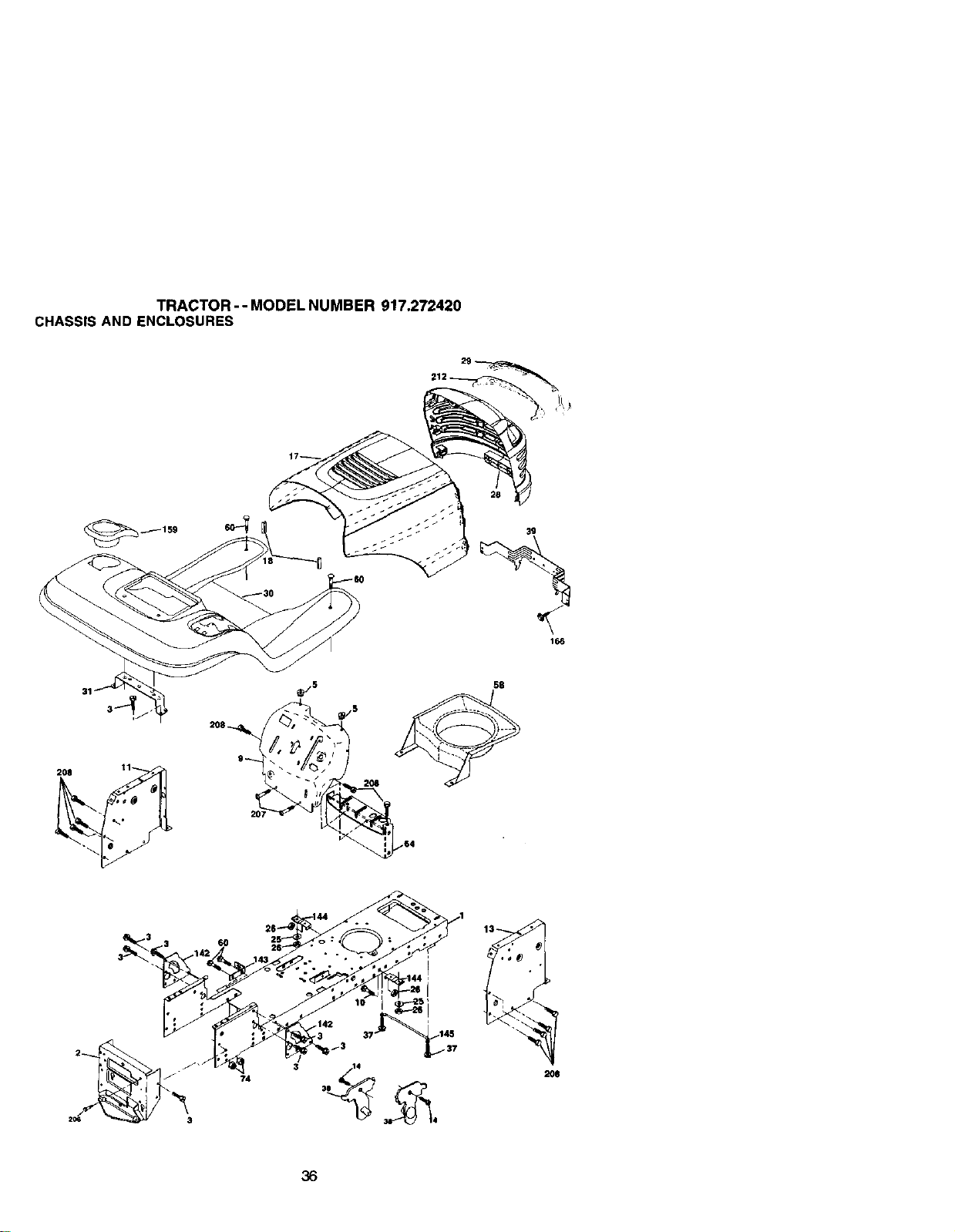
TRACTOR - - MODEL NUMBER 917.272420
CHASSIS AND ENCLOSURES
39
166
207
2O8
58
6O
74
36
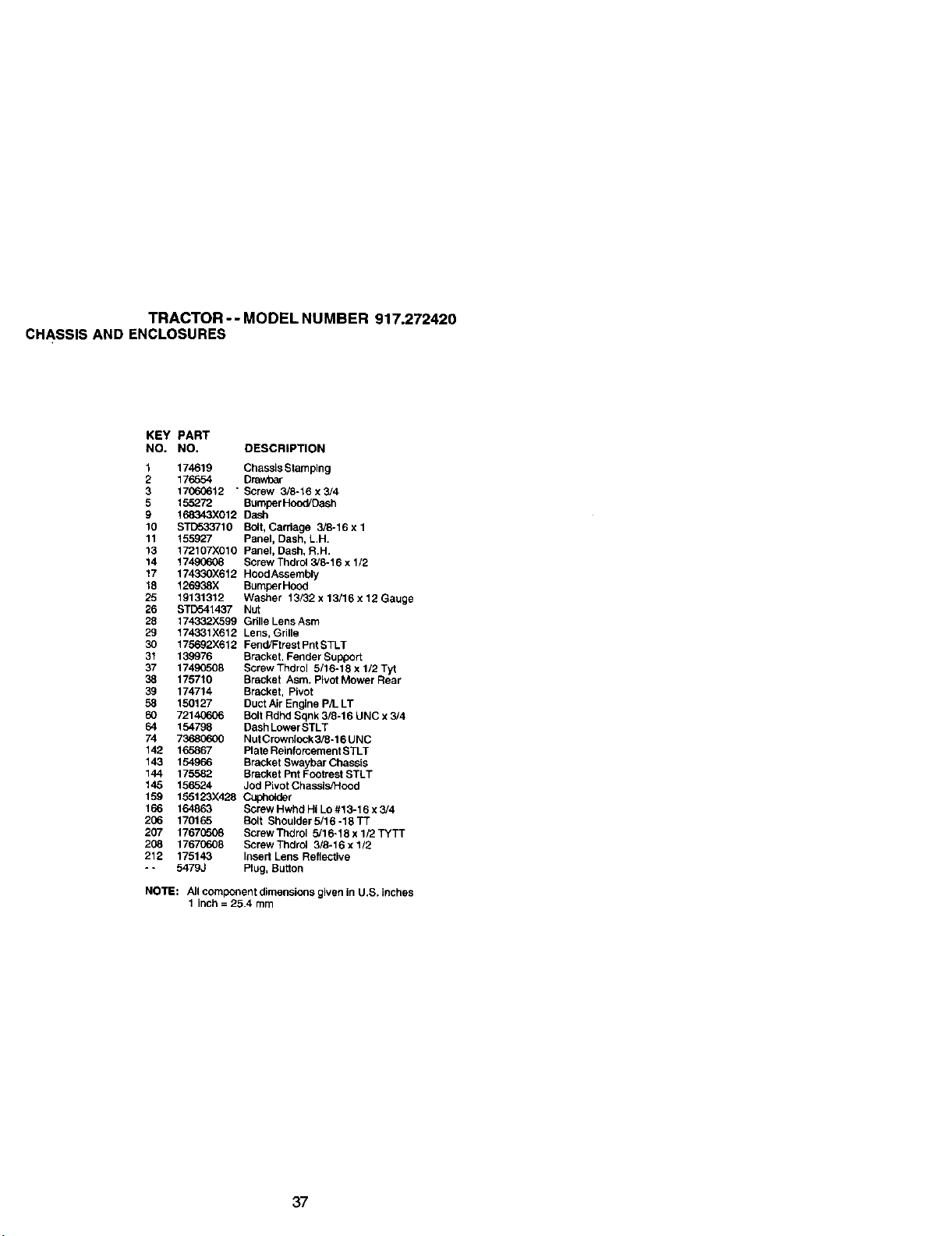
TRACTOR-- MODEL NUMBER 917.272420
CHASSIS AND ENCLOSURES
KEY PART
NO, NO, DESCRIPTION
1 174619 Chassis Stamping
2 176554 Drav/ear
3 17060612 " Screw 3/8-16x3/4
5 155272 Bumper Hood/Dash
9 168343X012 Dash
10 STD533710 Bolt, Cardage 3/8-16 x 1
11 155927 Panel, Dash, L,H,
13 172107X010 Panel, Dash, R,H,
14 17490608 Screw Thdrol 3/8-16 x 1/2
17 174330X612 Hood Assembly
18 126938X Bumper Hood
25 19131312 Washer 13/32 x 13/16 x 12 Gauge
26 STD541437 Nut
28 174332X599 Grille Lens Asm
29 174331X612 Lens, Grille
30 175692X612 Fend/Ftrest Pnt STLT
31 139976 Bracket, Fender Support
37 17490508 Screw Thdrol 5/16-18 x 1/2 Tyt
38 175710 Bracket Asm. Pivot Mower Rear
39 174714 Bracket, Pivot
58 150127 Duct Air Engine P/L LT
60 72140606 Bolt Rdhd Sqnk 3/8-16 UNC x 3/4
64 154798 Dash Lower STLT
74 7368(To00 Nut Crownlock 3/8-16 UNC
142 165867 Plate Reinforcement STLT
143 154966 Bracket Swaybar Chassis
144 175582 Bracket Pnt Footrest STLT
145 156524 Jod Pivot ChasslsS_ood
159 155123X428 C_ohc_der
166 164863 Screw Hwhd Hi Lo #13-16 x 3/4
206 170165 Bolt Shoulder 5/16 -18 TT
207 17670508 ScrewTndrol 5/16*18x1/2TYTT
206 17670608 Screw Thdrol 3/8-16 x 1/2
212 175143 Insert Lens Reflective
- - 5479J Plug, Button
NOTE: All component dimensions given in U.S. inches
1 inch = 25.4 mm
37
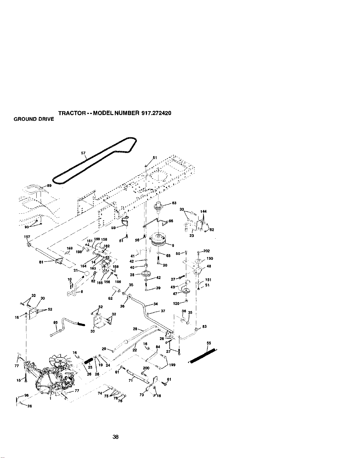
TRACTOR-- MODEL NUMBER 917.272420
GROUND DRIVE
23
144
200
61
55
38
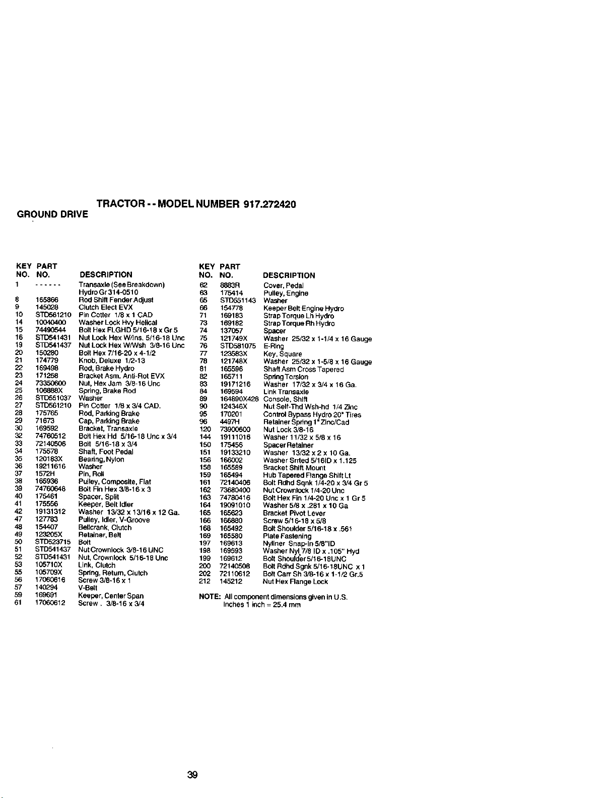
TRACTOR-- MODEL NUMBER 917.272420
GROUND DRIVE
KEY PART KEY
NO, NO. DESCRIPTION NO.
1 ...... Transaxle (See Breakdown) 62
HydroGr314-0510 63
8 165866 Rod Shift Fender Adjust 65
9 145G28 Clutch Elect EVX 66
10 STD561210 Pin Cotter 1/8 x 1 CAD 71
14 10040400 Washer Lock Hvy Helical 73
15 74490544 Bolt Hex FLGHD 5/16-18 x Gr 8 74
16 STD541431 Nut Lock Hex W/Ins. 5/16-18 Uric 76
19 $3_o41437 NutLockHexW/Wsh 3/8-16Unc 76
20 150_90 Bolt Hex 7/1 6-20 x 4-1/2 77
21 174779 Knob, Deluxe 1/3-13 78
22 169498 Rod, Brake Hydro 81
23 171258 Bracket Asm. Anti-Rot EVX 82
24 73350600 Nut, Hex Jam 3/9-16 Unc 83
25 106888X Spring, Brake Rod 84
26 STD551037 Washer 89
27 STD561218 Pin Cotter 1/8 x 3/4 CAB. 90 124346X
28 175765 Rod, Parking Brake 95 170201
29 71673 Cap, Parking Brake 96 4497H
30 169592 Bracket, Transaxle 120 73900600
32 74760512 BoltHexHd 5/16-18Uncx3/4 144 19111016
33 72140506 Bolt 5/16-18 x 3/4 150 175456
34 175578 Shaft, Foot Pedal 151 19133219
35 120183X Beadng, Nylon 156 166002
36 19211616 Washer 158 165589
37 1572H Pin, Roll 159 165494
38 165936 Putiey, Composite, Rat 161 72140406
39 74760648 Bolt Fin Hex 3/8-16 x 3 162 73680400
40 175461 Spacer, Split 163 74780416
41 175556 Keeper, Beft Idler 164 19091010
42 19131312 Washer 15/32 x 13/16 x 12 Ga. 165 165623
47 127783 Pulley, Idler, V-Groove 166 166880
48 154407 Bellcrank, Clutch 168 165492
49 123205X Retainer, Be8 169 165580
50 STD523715 Bolt 197 169613
51 STD541437 NutCrownlock 3/8-16UNC 198 169593
52 STD541431 Nut, Crownlock 5/16-18Unc 199 169612
53 105710X Link, Clutch 200 72140508
55 105709X Spdng, Return, Clutch 202 72110612
56 17060616 Screw 3/8-16 x 1 212 145212
57 140294 V-Belt
59 169691 Keeper, Center Span
61 17060612 Screw. 3/8-16 x 3/4
PART
NO, DESCRIPTION
8883R Cover, Pedal
175414 Polley, En_ne
STC55114.3 Washer
154778 Keeper Belt Engine Hydro
169183 Strap Torque Lh Hydro
169182 Strap Torque Rh Hydro
137057 Spacer
121749X Washer 25/32 x 1-1/4 x 16 Gauge
STO581075 E-Ring
123583X Key, Square
121748X Washer 25/32 x 1-5/8 x 16 Gauge
165596 Shaft Asm Cross Tapered
165711 SpshgToralon
19171216 Washer 17/32 x 3/4 x 16 Ga.
169594 Link Transaxle
164890X428 Console, Shift
Nut Self-Thd Wsh-hd 1/4 Zinc
Control Bypass Hydro 20" Tires
Retainer Sphng 1"Zinc/Cad
Nut Lock 3/8-16
Washer 11/32 x 5/8 x 16
Spacer Retainer
Washer 13/32 x 2 x 10 Ga.
Washer Srrted 5/16tD x 1.125
Bracket Shift Mount
Hub Tapered Flange Shift Lt
Bolt Rdhd Sqnk 1/4-20 x 3/4 Gr 5
Nut Crownlock 1/4-20 Unc
Bolt Hex Fin 1/4-20 Unc x 1 Gr 5
Washer 5/8 x .281 x 10 Ga
Bracket Pivot Lever
Screw 5/16-18 x 5/8
Bolt Shoulder 5/16-18 x .561
Plate Fastening
Nyliner Snap-In 5/8"1D
Washer Nyl 7/8 iD x .105" Hyd
Bolt Shoulder 5/16-18UNC
Bolt Rdhd Sgnk 5/16-18UNC x 1
Bolt Carr Sh 3_-16 x 1-1/2 Gr.5
Nut Hex Flange Lock
NOTE: AllcomponentdimensionsgiveninU.S.
Inches1 inch= 25.4mm
39
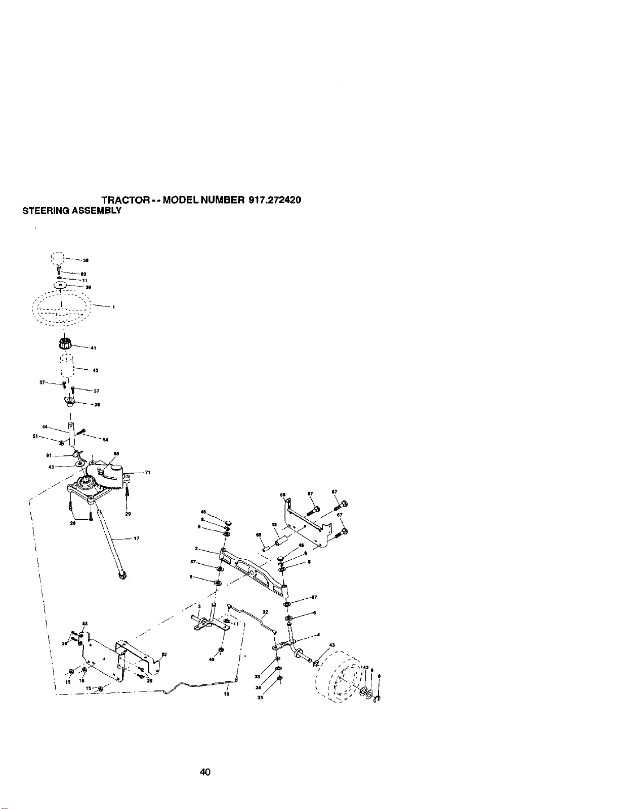
TRACTOR--MODELNUMBER917.272420
STEERINGASSEMBLY
_41
,L---_ 42
L ,
4O
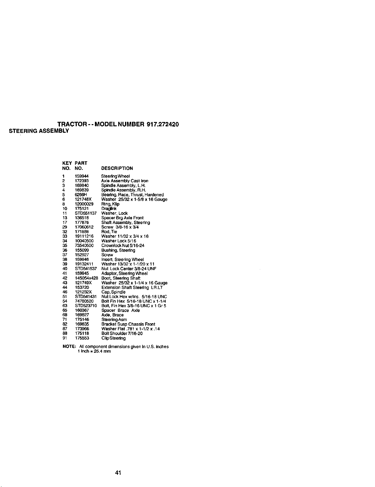
TRACTOR--MODELNUMBER917.272420
STEERINGASSEMBLY
KEY PART
NO, NO, DESCRIPTION
1
2
3
4
5
6
8
10
11
13
17
29
32
33
34
35
36
37
38
39
4O
41
42
43
44
46
51
54
63
65
68
71
82
87
88
91
159944 SteedngWheel
172393 Axle Assembly Cast Iron
169840 Spindle Asseml_y, LH.
169839 Spindle Assembly, R.H.
_66H Beadng, Race, Thrust, Hardened
121748X Washer 25/32 x 1-5/8 x 16 Gauge
12000029 Ring, Klip
175121 Draglink
STD551137 Washer, Lock
136518 Spacer Rrg Axle Front
177876 Shaft Assembly, Steering
17060612 Screw 3/8-16 x 3,/4
171888 Rod,Tie
19111216 Washer 11/32 x 3/4 x 16
10040500 Washer Lock 5/16
73540500 Crownlock Nut 5/16-24
155099 Bushing, Steedng
152927 Screw
159946 Insert, Steedng Wheel
19132411 Washer 13/32 x 1-1/20 x 11
STD541537 Nut Lock Center 3/8-24 UNF
159945 Adaptor, Steedng Wheel
145054x428 Boot, Steedng Shaft
121749X Washer 25/32 x 1-1/4 x 16 Gauge
153720 Extension Shaft Steedng LR.LT
121232X Cap,Spindle
STD541431 NutLockHexw/Ins. 5/16-18UNC
74780520 Bolt Fin Hex 5/16-18 UNC x 1-1/4
STD523710 Bolt, Fin Hex 3/8-16 UNC x 1 Gr 5
160367 Spacer Brace Axle
169827 Axle, Brace
175146 SteedngAsm
169835 Bracket Susp Chassis Front
173966 Washer Flat .781 x 1-I/2 x .14
175118 BoftShoulder 7/16-20
175553 Clip Steedng
NOTE: All component dimensions given In U.S. inches
1 inch = 25.4 mm
41
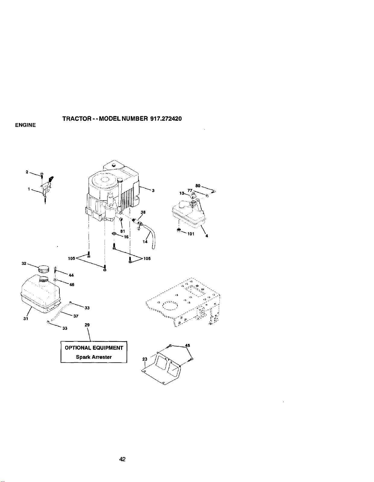
ENGINE
TRACTOR - - MODEL NUMBER 917.272420
! 81
31
J" _37
33
/
OPTIONAL EQUIPMENT
Spark Arrester
r
8O
38
14
42
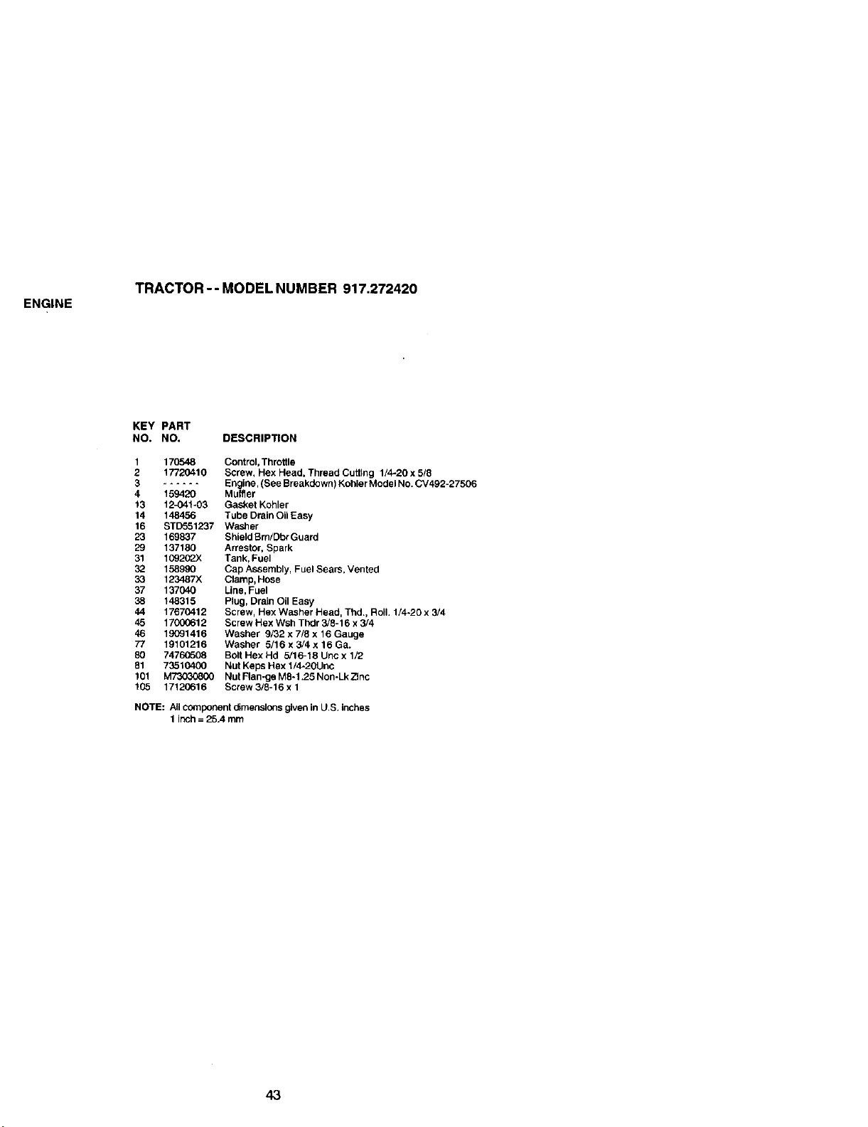
ENGINE
TRACTOR-- MODELNUMBER 917.272420
KEY PART
NO. NO. DESCRIPTION
1 170548 Control, Throttle
2 17720410 Screw, Hex Head, Thread Cuffing 1/4-20 x 5/8
3 ...... Engine, (See Breakdown) Kohler Model NO.CV492-27506
4 159420 Muffler
13 12_41-03 Gasket Kohler
14 148456 Tube Drain Oil Easy
16 STD551237 Washer
23 169837 Shield Brn/Dbr Guard
29 137180 Arrestor, Spark
31 109202X Tank, Fuel
32 158990 Cap Assembly, Fuel Sears, Vented
33 123487X Clamp, Hose
37 137040 Line, Fuel
38 148315 Plug, Drain Oil Easy
44 17670412 Screw, Hex Washer Head, Thd. Roll. 1/4-20 x 3/4
45 17000612 Screw Hex Wsh Thdr 3/8-16 x 3/4
46 19091416 Washer 9/32 x 7/8 x 16 Gauge
77 19101216 Washer 5/16 x 3/4 x 16 Ga.
80 74760508 Bolt Hex Hd 5/16-18 Uno x 1/2
81 73510400 Nut Keps Hex 1/4-20Unc
101 M_ Nut Flan-ge M8-1.25 Non-Lk Zinc
105 17120616 Screw 3/8-16 x 1
NOTE: All component olmenslons given in U.S. inches
1 inch = 25.4 mm
43
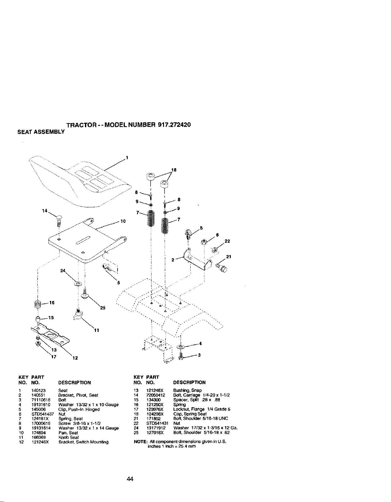
TRACTOR-- MODEL NUMBER 917.272420
SEAT ASSEMBLY
\
\ \
24 I i
_15
17 12
18
I i
i t
I I
I I
KEY PART
NO. NO. DESCRIPTION
1 140123 Seat
2 140551 Bracket, Pivot, Seat
3 71110616 Bolt
4 19131610 Washer 13/32 x 1 x 10 Gauge
5 145006 Clip, Push-In Hinged
6 STD541437 Nut
7 124181X Spring, Seat
8 1700_616 Screw 3/8-16 x 1-1/2
9 19131614 Washer 13/32 x 1 x 14 Gauge
10 174894 Pan, Seat
11 166369 Knob Seat
12 121246X Bracket. Switch Mounting
KEY
NO.
13
14
15
16
17
18
21
22
24
25
PART
NO. DESCRIPTION
121248X Bushing, Snap
72050412 Bolt, CalTlage 1/4-20 x 1-1/2
134300 Spacer, Split .26 x .88
121250X Spring
123976X Locknut, Flange 1/4 Grade 5
124238X Cap, Spdng Seat
171852 Bolt, Shoulder 5/16-18 UNC
STD541431 Nut
19171912 Washer 17/32 x 1-3/16 x 12 Ga.
127018X Bolt, Shoulder 5/16-18 x .62
NOTE: All component dimensions given In U.S.
inches 1 inch = 25.4 mm
44
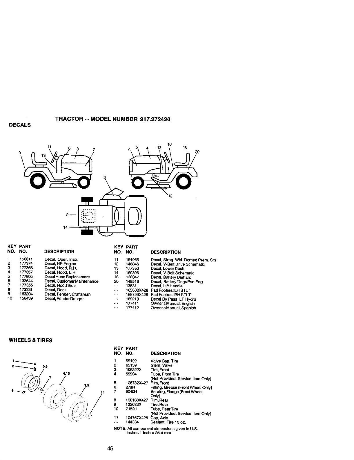
DECALS
TRACTOR -- MODEL NUMBER 917.272420
11 5 4 13 10 16
9 13 6 3 7 7 1 20
KEY PART KEY PART
NO. NO. DESCRIPTION NO, NO, DESCRIPTION
1 156811 Decal, Ober. Instr. 11 164065 Decal, Strng. Whl. Domed Prem. Srs
2 177374 Decai, HP Engine 12 146046 Decal, V-Belt Drive SchemalJc
3 177356 Decal, Hood, R.H. 13 177350 Decal, Lower Dash
4 177357 Decal, Hood, L,H. 14 160396 Decal, V-Belt Schernatic
5 177805 Decal Hood Replacement 16 138047 Decal, Battery Diehard
6 133644 Decal,CustomerMaintenance 20 149516 Decal, Battery Dngr/Psn Eng
7 177355 Decal, Hood Side -- 138311 Decal, Lift Handle
8 172331 Decal, Deck -- 165800X428 Pad Footrest LH STLT
9 163204 Decal, Fender, Craftsrnan -- 165799)(428 Pad Footrest RH STLT
10 156439 Decal, Fender Danger -- 169210 Decal By Pass LT Hydro
- - 177411 Owner's Manual, English
* - 177412 Owner's Manual, Spanish
WHEELS & TIRES
4,10
3,9
11
KEY PART
NO. NO. DESCRIPTION
1 59192 Valve Cap, Tire
2 65139 Stem, Valve
3 106222X Tire,Front
4 59904 Tube, Front Tire
(Not Provided, Service Item Only)
5 106732X427 Rim, Front
6 278H Fiffing, Grease (Front Wheel Only)
7 9040H Bearfng, Flange (Front Wheel
Only)
8 106108X427 Rim, Rear
9 122082X Tire, Rear
t0 7152J Tube, Rear Tire
(Not Provided, Service Item Only)
11 104757X428 Cap, Axle
- - 144334 Sealant, Tire 10 oz.
NOTE: All component dimensions given InU.S.
inches 1 inch = 25.4 mm
45
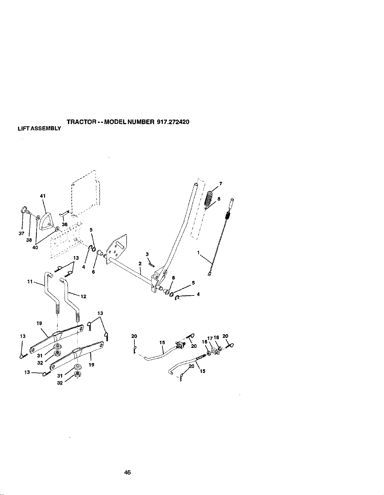
TRACTOR - - MODEL NUMBER 917.272420
LIFTASSEMBLY
2O
15
/ /
/ /
/ /
6
5
20
15
46
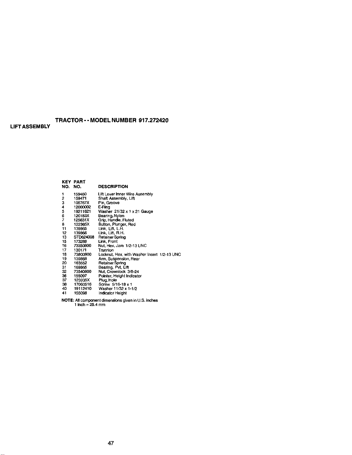
TRACTOR- - MODEL NUMBER 917.272420
LIFTASSEMBLY
KEY PART
NO. NO. DESCRIPTION
1 159460 Lift Lever Inner Wire Assembly
2 159471 Shaft ASSembly, Lift
3 105767X Pin, Groove
4 12006002 E-Ring
5 19211621 Washer 21/32 x 1 x21 Gauge
6 120183X Beadng, Nylon
7 125631X Gdp, Handle, Fluted
8 122365X Button, Plunger, Red
11 139865 Link, Lift, LH.
12 139866 Link, Lib, R.H.
13 STD624008 Retainer Spdng
15 173288 Link, Front
16 73350800 Nut, Hex, Jam 1/2-13 UNC
17 130171 Trunnion
18 73800800 Locknut, Hex, with Washer Insert 1/2-13 UNC
19 139868 Ann, Suspension, Rear
20 163552 Retainer Spring
31 169865 Beadng, Pvt, Lift
32 73540600 Nut, Crownlock 3/8-24
36 155097 Pointer, Height Indicator
37 123935X Plug, Hole
38 17060516 Screw 5/16-18 x 1
40 19112410 Washer 11/32. x 1-1/2
41 155098 Indicator Height
NOTE: All component dimensions given in U,S. inches
1 inch = 25.4 mm
47
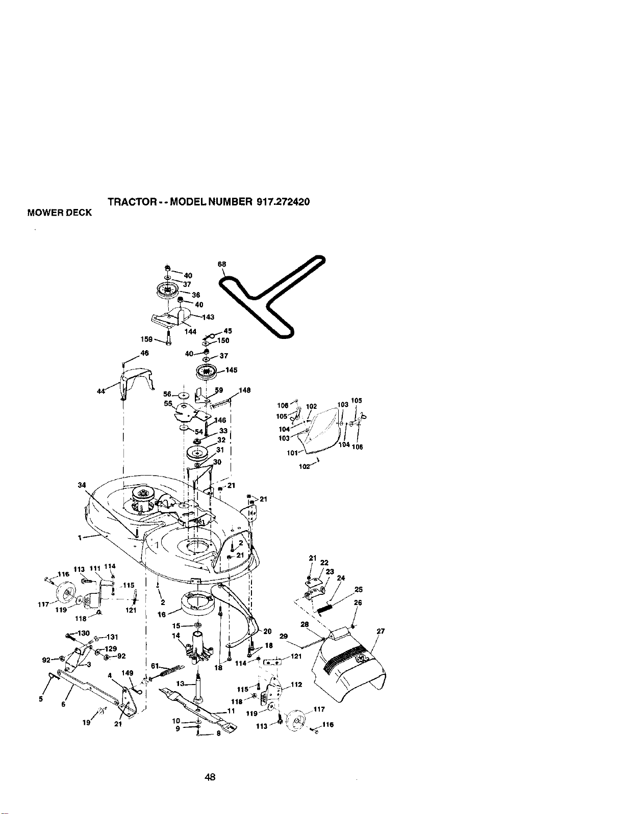
TRACTOR -- MODEL NUMBER 917.272420
MOWERDECK
34
"_'40
_3736
40 37
44_'_ 55, 145
/_ !05
106 ' 102 103
_o3J_/_- // /
101/'_ 104 106
116 113 111 114
118 _
5
6
19// 21
16
1
_.18
21 22
23 24
_ 6
28
'
,.j
117
_116
48
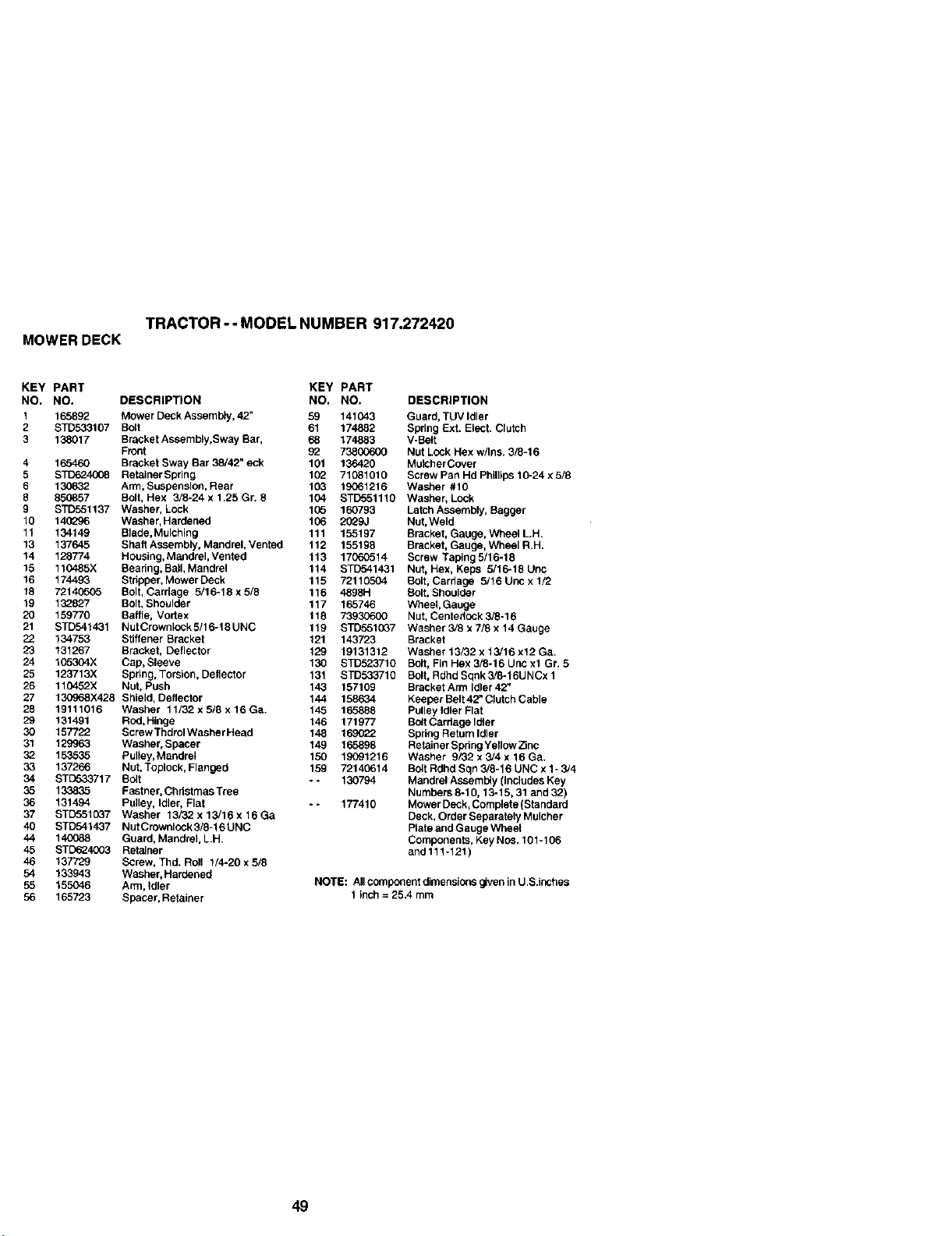
TRACTOR -- MODEL NUMBER 917.272420
MOWER DECK
KEY PART KEY PART
NO. NO. DESCRIPTION NO. NO,
1 165892 Mower Deck Assembly, 42" 59 141043
2 STD533107 Bo_t 61 174882
3 138017 Bracket Assembly,Sway Bar, 68 174883
Front 92 738G0600
4 165460 Bracket Sway Bar 38/42" eck 101 136420
5 STD624008 RetainerSpring 102 71081010
6 130_32 Arm, Suspension, Rear 103 19061216
8 850857 Bolt, Hex 3/8-24 x 1.25 Gr. 8 104 STD551110
9 STD551137 Washer, Lock 105 160793
10 140_J6 Washer, Hardened 106 2029J
11 134149 Blade, Mulching 111 155197
13 137645 Shaft Assembly, Mandrel, Vented 112 155198
14 128774 Housing, Mandrel,Vented 113 1706G514
15 110485X Beadng, Ball, Mandrel 114 STD541431
16 174493 Stripper, Mower Deck 115 72110504
18 72140505 Bolt, Carriage 5/16-18x5/8 116 4898H
19 132827 Bolt, Shoulder 117 165746
20 159770 Baffle, Vortex 118 73930600
21 STD541431 NutCrown[ock5/16-18UNC 119 STD5510B7
22 134753 Stiffener Bracket 121 143723
23 131267 Bracket, Deflector 129 19131312
24 105304X Cap, Sleeve 130 STD523710
25 123713X Spring, Torsion, Deflector 131 STD533710
26 110452X Nut, Push 143 157109
27 130968X428 Shield, Deflector 144 158634
28 19111016 Washer 11/32 x 5/8 x 16 Ga. 145 165888
29 131491 Rod, Hinge 146 171977
30 157722 Screw ThdrolWasher Head 148 169022
31 129963 Washer, Spacer 149 165898
32 153535 Pulley,Mandrel 150 19091216
33 137266 Nut, Toplock, Flanged 159 72140614
34 STETo33717 Bolt - - 130794
35 133835 Fastner, Christmas Tree
36 131494 Pulley, Idler, Flat - - 177410
37 STD5510_7 Washer 13/32. x13/16x16Ga
40 STD541437 Nut Crownlock 3/8-16 UNC
44 140088 Guard, Mandrel, L.H,
45 STD624003 Retainer
46 137729 Screw, Thd. Roll 1/4-20 x 5/8
54 133943 Washer, Hardened
55 155046 Arm, Idler
56 165723 Spacer, Retainer
DESCRIPTION
Guard, TUV Idler
Spring Ext. Elect. Clutch
V-Belt
Nut Lock Hex w/Ins. 3/8-16
Mulcher Cover
Screw Pan Hd Phillips 10-24 x 5/8
Washer #10
Washer, Lock
Latch Assembly, Bagger
Nut,Weld
Bracket, Gauge, Wheel L.H.
Bracket, Gauge, Wheel R.H.
Screw Taping 5/16-18
Nut, Hex, Keps 5/16-18 Unc
Bolt, Cardage 5/16 Unc x 1/2
Bolt, Shoulder
Wheel, Gauge
Nut, Centadock 5/8-16
Washer 3/8 x 7/8 x 14 Gauge
Bracket
Washer 13/82 x 13/16 x12 Ga.
Bolt, Fin Hex 3/6-16 Unc xl Gr. 5
Bolt, Rdhd Sqnk 3/8-16UNCx 1
Bracket Arm Idler 42"
Keeper Belt 42_ Clutch Cable
Pulley Idler Flat
Bolt Cardege Idler
Spring Retain Idler
Retainer Spdng Yellow Z_nc
Washer 9/82 x 3/4 x 16 Ga.
Bo4tRdhd Sqn 3/6-16 UNC x 1- 3/4
Mandrel Assembty (includes Key
Numbers 8-10, 13-15, 31 and 32)
Mower Deck, Complete (Standard
Deck, Order Separately Mulcher
Plate and Gauge Wheel
Components, Key NOS. 101-106
and111-121)
NOTE: All component dimensions given in U.S.inshes
1 Inch = 25.4 mm
49
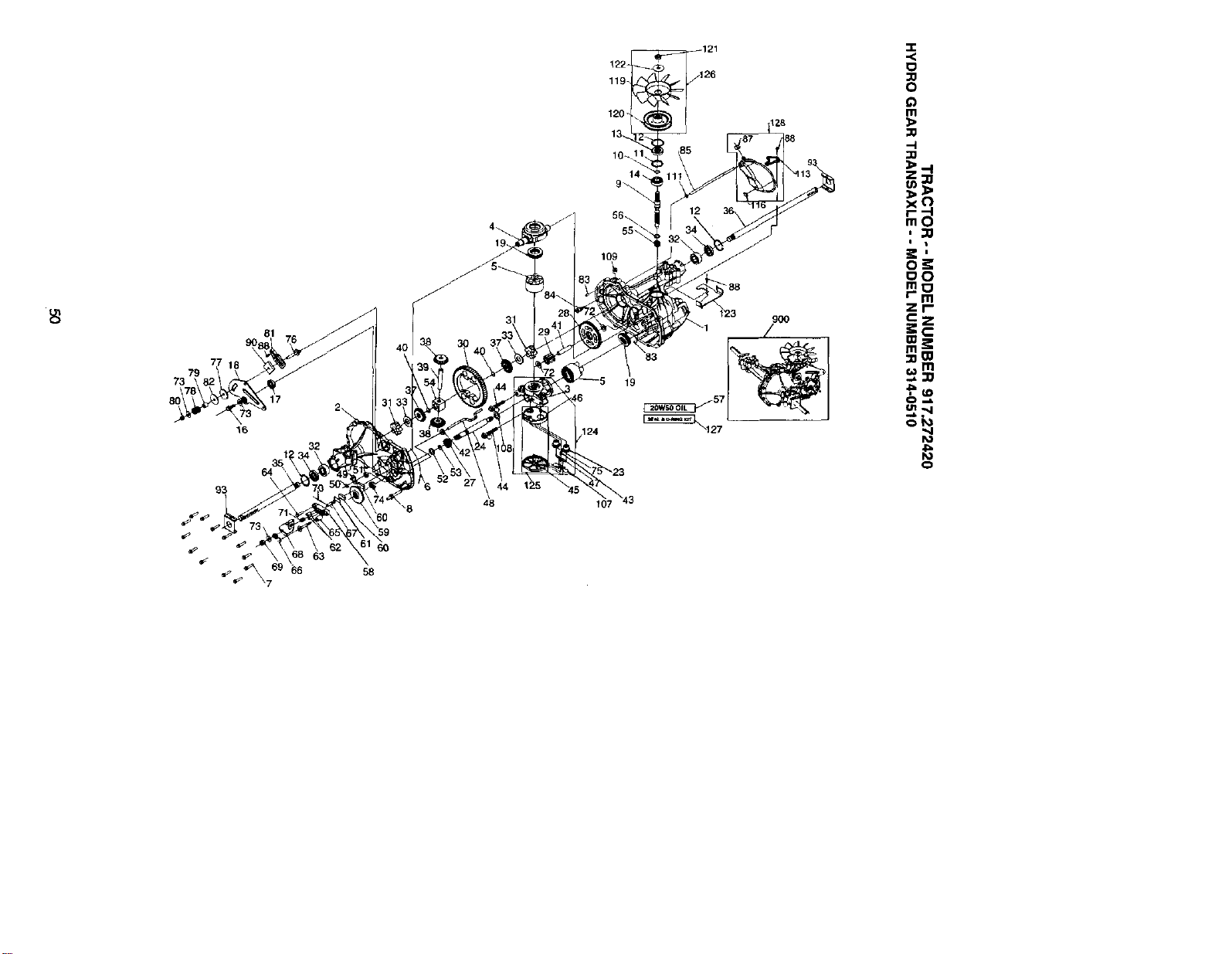
81
79
73
17
16
93
69
_7 66
58
119
120
14
109
19
124
107 43
128
12
88
123
9OO
/
-r
,,<
0
¢)
Ill
x('}
I t
o_
o0
mt_
r m
zr
!i
o_
0
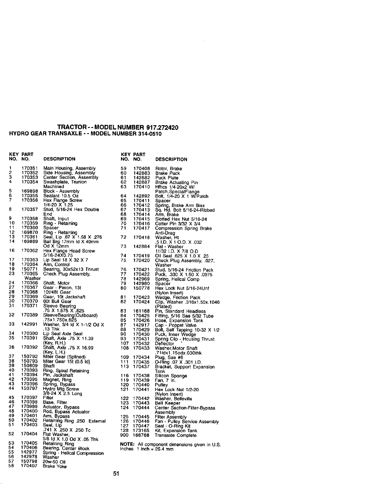
TRACTOR - - MODEL NUMBER 917.272420
HYDRO GEAR TRANSAXLE - - MODEL NUMBER 314-0510
KEY PART KEY PART
NO. NO. DESCRIPTION NO. NO. DESCRIPTION
1 170351 Main Housing, Assembly 59 170408 Rotor, Brake
2 170352 Side Housing, Assembly 60 142883 Brake Puck
3 170353 Center Section, Assembly 61 142882 Puck Plate
4 170354 Swashplate, Trunion 62 142887 Brake Actuating Pin
Machined 63 170410 Hfhcs 1/4-20x2. W/
5 169898 BlOCk- Assembly Patch,SpecialFlan e
6 170355 Sealant 10.50z 64 142892 Bolt, I/4-20 X 1 _/Patch
7 170356 Hex Flange Screw 65 170411 Spacer
1/4-20 X 1.25 66 170412 Spdne, Brake Arm Bias
8 170357 Stud, 5/16-24 Hex Double 67 170413 Sq. H"d. Bolt 5/16-24-Ribbed
End 66 170414 Arm, Brake
9 170358 Shaft, Input 69 170415 Slotted Hex Nut 5/16-24
10 170359 Ring - Retaining 70 170416 Cotter Pin 3/32 X 3/4
11 170360 Spacer 71 170417 Compression Spring Brake
12 169870 Rin - Retaining Anti-Drag
13 170361 Sea_ X 170418 Washer, Ht
, Lip .67 X 1.58 .276 72
14 169869 Ball Brg 17mm Id X 4Ornm .5 I.D. X 10.D. X .032
Od X 12mm 73 142884 Flat- Washer
16 170362 Hex Flange Head Screw 11/32 I.D. X 7/80.D
5/16-24X0.75 74 170419 Oil Seal .625 X 1.0 X .25
17 170363 Lip Seal 18 X 32 X 7 75 170420 Check Plug Assembly, .027,
18 170364 Arm, Control Washer
19 150771 Bearing, 30x52x13 Thrust 76 170421 Stud, 5/16-24 Friction Pack
23 170365 Check Plug Assembly, 77 170422 Puck, .330 X 1.50 X .0975
Washer 78 142969 Spring, Helical Cornp
24 170366 Shaft, Motor 79 142980 Spacer
27 170367 Gear - Pinion, 131 80 150778 Hex Lock Nut 5/16-24Unf
28 170368 10t/481 Gear (Nylon Insert)
29 170369 Gear, 101Jackshaft 81 170423 Wedge, Friction Pack
30 170370 60t Bull Gear 82 170424 Clip, Washer .316x1.50x.1046
31 170371 Sleeve Bearing (Plated
.75 X 1.578 X .625 83 161168 P n, Standard Headless
32 170389 SleeveBeadng(Outboard) 84 170425 Fitting, 5/16 Sae 5/32 Tube
.75x1.750x.625 85 170426 Hose, Expansion Tank
33 142991 Washer, 3/4 Id X 1-1/20d X 87 142917 Cap - Poppet Valve
.13 Thk 88 170429 Bolt, Self Tapping 10-32 X 1/2
34 170390 Lip Seal Axle Seal 90 170430 Puck, Inner Wedge
35 170391 Shaft, Axle .75 X 11.39 93 170431 Spring Clip - Housing Thrust
(Key, R.H.) 107 170432 Deflector "
36 170392 Shaft, Axle .75 X 16.99 108 170433 Washer, Motor Shaft
(Key, L.H.) .711dx1.15odx.030thk
37 150792 Miter Gear (Splined) 109 170434 Plug, See #6
38 150793 Miter Gear 151 (0.5 Id) 111 170435 O-Ring .07 X .301 I.D.
39 150809 Shaft 113 170437 Bracket, Support Expansion
40 170393 Ring, Spiral Retaining Tank
41 170394 Pin, Jackshaft 116 170438 Silicon Sponge
42 170395 Magnet, Ring 119 170439 Fan, 7 In.
43 170396 Spnng, Bypass 120 170440 Pulley
44 150797 Hydro Mtg Screw 121 170441 Hex Lock Nut I/2-20
3/8-24 X 2.5 Long (Nylon Insert)
45 170397 Filter 122 170442 Washer, Selleville
46 170398 Base, Filter 123 170443 Belt Keeper
47 170999 Actuator, Bypass 124 170444 Center Section-Filter-Bypass
48 170400 Rod, Bypass Actuator Assembly
49 170401 Arm, Bypass 125 170445 Filter Assembly
50 170402 Retaining Ring .250 External 126 170446 Fan - Pulley Service Assernbly
51 170403 Seal, Lip 127 170447 Seal - O-Ring Kit
.741 X .250 X .250 TC 128 173165 Kit, Expansion Tank
52 170404 Flat Washer, 900 166768 Transaxle Complete
5/8 Id X 1.00d X .05 Thk
53 170405 Retaining Ring NOTE: All component dimensions g_ven in U.S.
54 170406 Bearing, Center Block inches 1 inch = 25.4 mm
55 142977 Spring - Helical Compression
56 142978 Washer
57 150798 20w-50 Oil
58 170407 Brake Yoke
51
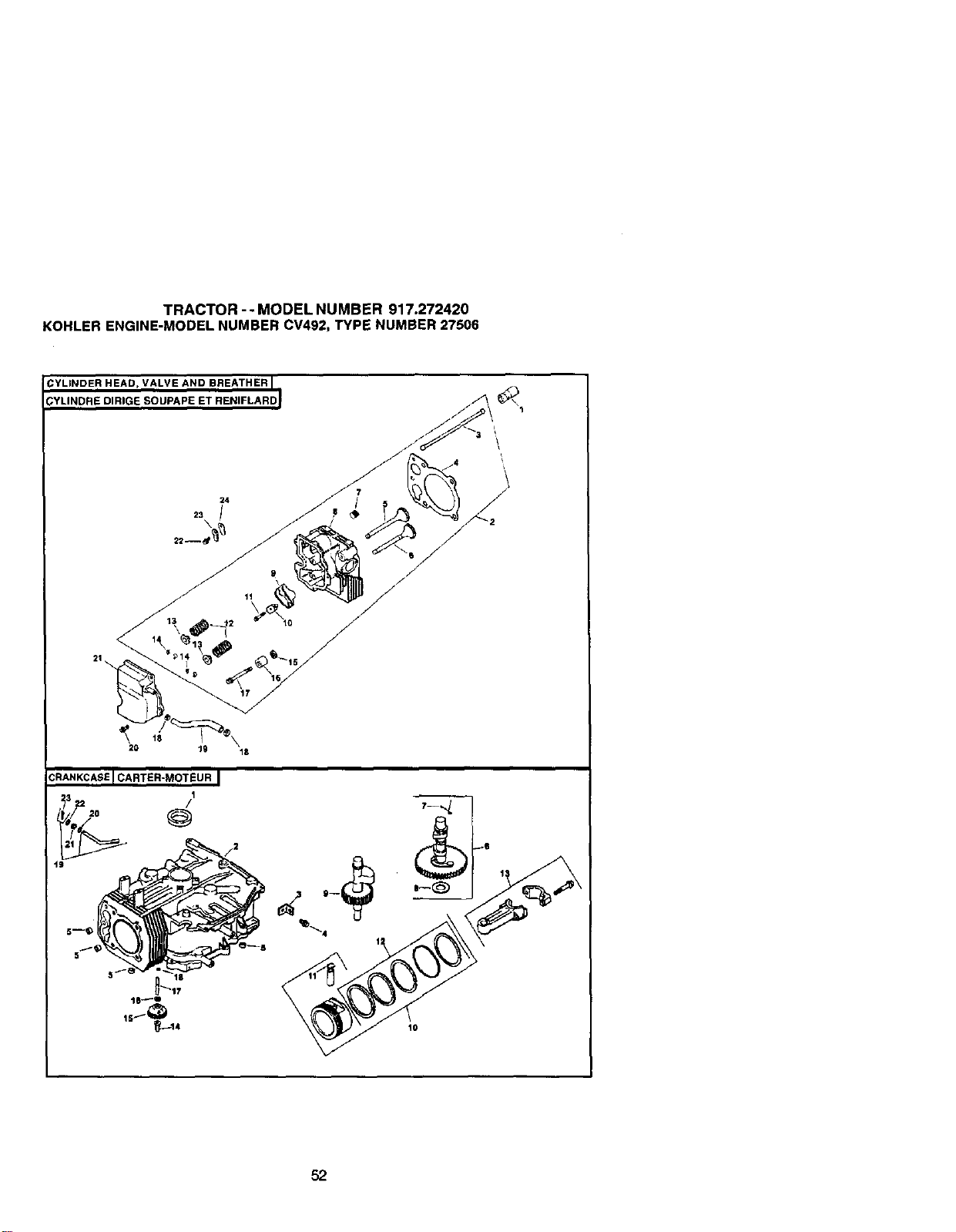
TRACTOR -- MODEL NUMBER 917.272420
KOHLER ENGINE-MODEL NUMBER CV492, TYPE NUMBER 27506
YLINDER HEAD, VALVE AND BREATHER I
YLINDRE DIRIGE SOUPAPE ET RENIFLARDI
1
20 lg
CRANKCASE I CARTER-MOTEUR I
t9
52
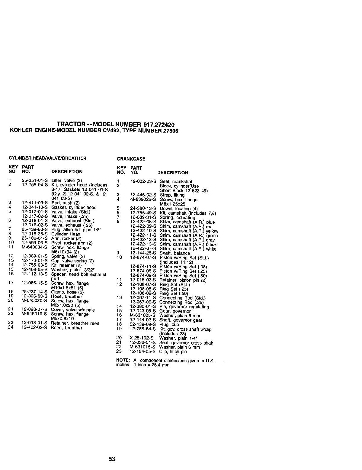
TRACTOR - - MODEL NUMBER 917.272420
KOHLER ENGINE-MODEL NUMBER CV492, TYPE NUMBER 27506
CYLtNDER READ/VALVE/BREATHER
CRANKCASE
KEY PART KEY PART
NO. NO. OESCRIPTION NO. NO. DSSCRIP_ON
1 25-351-01-S Lifter valve !2 1 12-032-03-S
2 12-755-94-S Kit, cylindernead ncudes 2
3-17, Gaskets 12 041 01-S
Qty. 2),12 041 02-S, & 12 3 12-445-02-S
041 03-5 4 M-839025-S
3 12-41t-03-S Rod, push (2)
4 12-041-10-S Gasket, cylinder head 5 24-380-13-S
5 12-017-01-S Valve, intake (Std.) 6 12-755-49-S
12-017-02-S Valve, intake .25) 7 12-089-31-S
6 12-015-01-S Valve, exhaust Std.) 8 12-422-08-S
12-016-02-S Valve, exhaust .25) 12-422-09-S
7 25-139-60-S Plug, allen hd. ppe 1/8 12-422-10-S
8 12-318-36-S Cylinder Head 12-422-11-S
9 25-186-01-S Arm, rocker (2) 12-422-12-S
10 12-599-03-S Pivot, rocker arm (2) 12-422-13-S
t f M-640034-S Screw, hex. flange 12-422.07-S
M6xk0x34 (2) 9 12-144-28-S
12 12-089-01-S Spring, valve (2) 10 12-874-07-S
13 12-173o01-S Cap, valve spring (2)
14 12-755-03-S KiL retainer (2) 12-874-11-S
15 12-468o05-S Washer, plain 13/32" 12-874-08-S
16 12-112o13-S Spacer, head bolt exhaust 12-874-09-S
port 11 12 018 02-S
17 12-086-t5-S Screw, hex. f_ange 12 12-t08-07-S
M10x1.5x81 (5) 12-108-05-S
18 25-237-14-S Clamp, hose (2) 12-108-09-S
19 12-326-03-S Hose, breather 13 12-067-11-S
20 M-645020-S Screw, hex, flange 12-067-05-S
M6x1,0x2O (5) 14 12-380-01-S
21 12-096-07-S Cover, valve w/nipple 15 12-043-05-S
22 M-545010-S Screw, hex. flange 16 M-531005-S
M5x0.8x 10 17 12-144-02-S
23 12-018-01-S Retainer, breather reed 18 52-139-09-S
24 12-402-02-S Reed, breather 19 12-755.64-S
20 X-25-102-S
21 12-032°01-S
22 M-631015-S
23 12-154-05-S
Seal, crankshaft
Block, cylinder(Use
Short Block 12 522 49)
Strap, lifting
Screw, hex. flange
Max1.25:<25
Dowel, lOCating (4)
Kit, camshaft (Includes 7,8)
Spring, actuating
Shim, camshaft (A.R.) btue
Shim, camshaft (A.R. red
Shim, camshaft (A.R.) yellow
Shim, camshaft (A.R.) green
Shim, camshaft (A.R.) gray
Shim camshaft (A.R. black
Shim, camshaft (A.R. white
Shaft, batance
Piston w/Ring Set (Std.)
plneludes 11,12)
iston w/Ring Set (.08)
Piston w/Ring Set (.25)
Piston w/Ring Set (.50)
Retainer, piston pin (2)
Ring Set (Std.)
Ring Set .25
Ring Set 1.50{
Connecting Rod }.S2tdi)
Connecting Rod
Pin, governor regulating
Gear, governor
Washer, ptain 5 mm
Shaft, governor gear
Plug, cup
Kit, gov.cross shaft w/clip
Includes 23)
Washer, pan 1/4"
Seal, governor cross shaft
Washer, ptain 6 mm
Clip, hitch pin
NOTE: All component dimensions given in U.S.
inches I inch = 25.4 mm
53
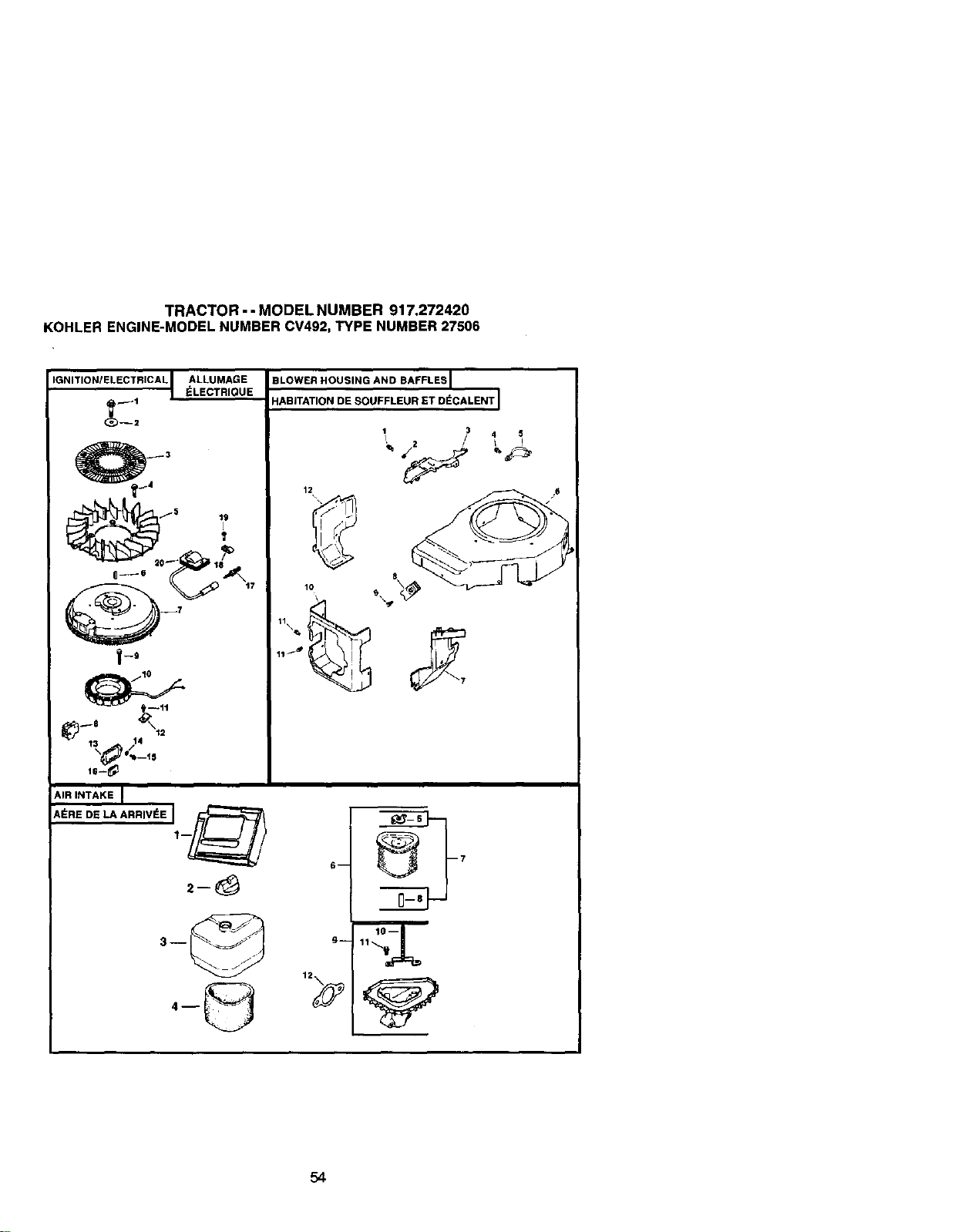
TRACTOR - - MODEL NUMBER 917.272420
KOHLER ENGINE-MODEL NUMBER CV492, TYPE NUMBER 27506
IGNITIONIELECTRICAL t ALLUMAGE_LECTRIQUE
_3
12
--7
1t\,_
13 14
AIR INTAKE I
A_REDE_ ARRIVSEJ1._/_
3--
BLOWER HOUSING AND BAFFLES I
HABITATION DE SOUFFLEUR ET D_CALENT J
4 $
lO
6-- _7
54
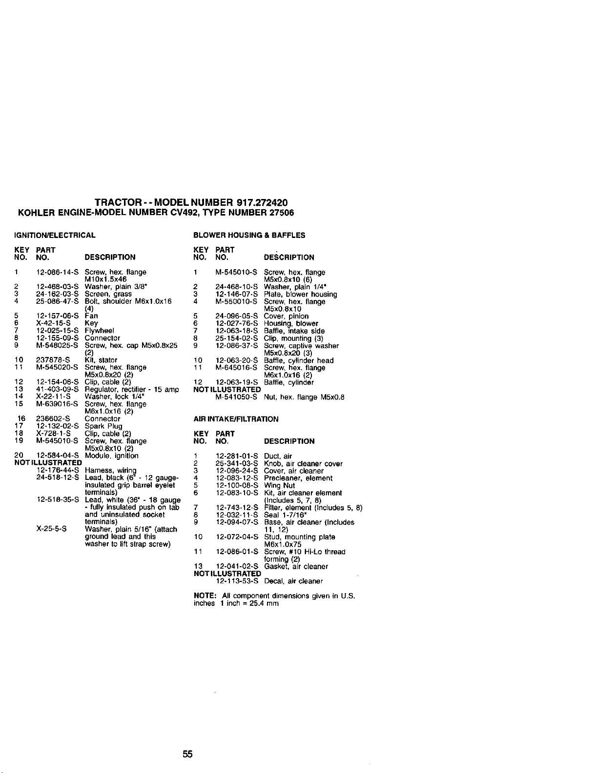
TRACTOR--MODELNUMBER917.272420
KOHLERENGINE-MODELNUMBERCV492,TYPENUMBER27506
IGNITION/ELECTRICAL BLOWER HOUSING & BAFFLES
KEY PART KEY PART
NO. NO. DESCRIPTION NO. NO, DESCRIPTION
1 12-086-14-S Screw, hex. flange 1 M-545010-S Screw, hex. flange
M10x1.5x46 M5x0.8xlO (6)
2 12-468-03-S Washer, plain 3/8" 2 24-468-10-S Washer, plain 1/4"
3 24-162-03-S Screen, grass 3 12-146-07-S Plate, blower housing
4 28-086-47-S Bolt, shoulder M6x1.0x16 4 M-550010-S Screw, hex. flange
(4) M5xO,Sxl0
5 12-157-06-S Fan 5 24-096-05-S Cover, pinion
6 X-42-15-S Key 6 12-027-76-S Housing, blower
7 12-025-15-S Flywheel 7 12-063-18-S Baffle, intake side
8 12-155-09-S Connector 8 25-154-02-S Clip, mounting (3)
9 M-548025-S Screw, hex. cap M5x0.8x25 9 12-086-37-S Screw, captive washer
(2) MSxO.8x2O (3)
10 237878-S Kit, stator 10 12-063-20-S Baffle, cylinder head
11 M-545020-S Screw, hex. flange 11 M-645016-S Screw, hex. flange
M5x0.8x20 (2) M6x1.Ox16 2)
12 12-154-06-S Clip, cable (2) 12 12-063-19-S Baffe, cyinder
13 41-403-09-S Regulator, rectifier- 15 amp NOTILLUSTRATED
14 X-22-11-S Washer, lock 1/4" M-541080-S Nut, hex flange M5x0.8
15 M-63g016-S Screw, hex. flange
M6x1,0x16 (2)
16 236602-S Connector AIR INTAKE/FILTRATION
17 12-132-02-S Spark Plug
18 X-728-1-S Clip, cable (2) KEY PART
19 M-545010-S Screw, hex. flange NO. NO, DESCRIPTION
M5xO.8xl0 (2)
20 12-584-04-S Module, ignition 1 12-281-01-S Duct, air
NOTILLUSTRATED 2 25-341-03-S Knob, air cleaner cover
12-176-44-S 3 12-096-24-S Cover, air cleaner
24-518-12-S 4 12-083-12-S Precleaner, element
12-518-35-S
Harness, wirin_l
Lead, black (6 - 12 gauge-
insulated grip barrel eyelet
terminals)
Lead, white (36" - 18 gauge
- fully insulated push on tab
and uninsulated socket
terminals)
Washer, plain 5/16" (attach
ground lead and this
washer to lift strap screw)
X-25-5-S
5 12-100-08-S Wing Nut
6 12-083-10-S Kit, air cleaner element
(Includes 5, 7, 8)
7 12-743-12-S Filter, element (includes 5, 8)
8 12-032-11-S Seal 1-7/16"
9 12-094-07-S Base, air cleaner (Includes
11, 12)
10 12-072-04-S Stud, mounting plate
M6x1.0x75
11 12-086-01-S Screw, #10 Hi-Lo thread
forming (2)
13 12-041-02-S Gasket, air cleaner
NOT ILLUSTRATED
12-113-53-S Decal, air cleaner
NOTE: All component dimensions given in U.S.
inches 1 inch = 25.4 mm
55
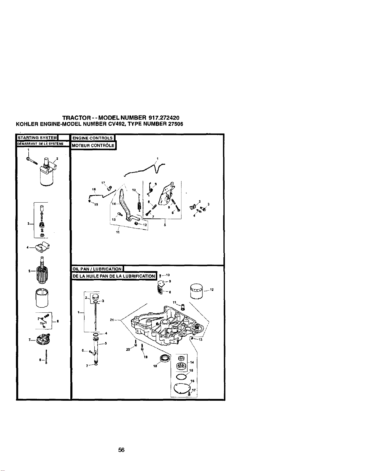
TRACTOR - - MODEL NUMBER 917.272420
KOHLER ENGINE-MODEL NUMBER CV492, TYPE NUMBER 27506
STARTING SYSTEM|
D_MARRANT DE L_ SYST_ME
1
I
0
.t
ENGINE CONTROLS
MOTEUR CONTROLE
t
/
11
2
/ 3
4'
t--
OIL PAN I LUBRICATION |
DE LA HUILE PAN DE LA LUBRIFICATION _--t0
_,, Z.-3 11
56
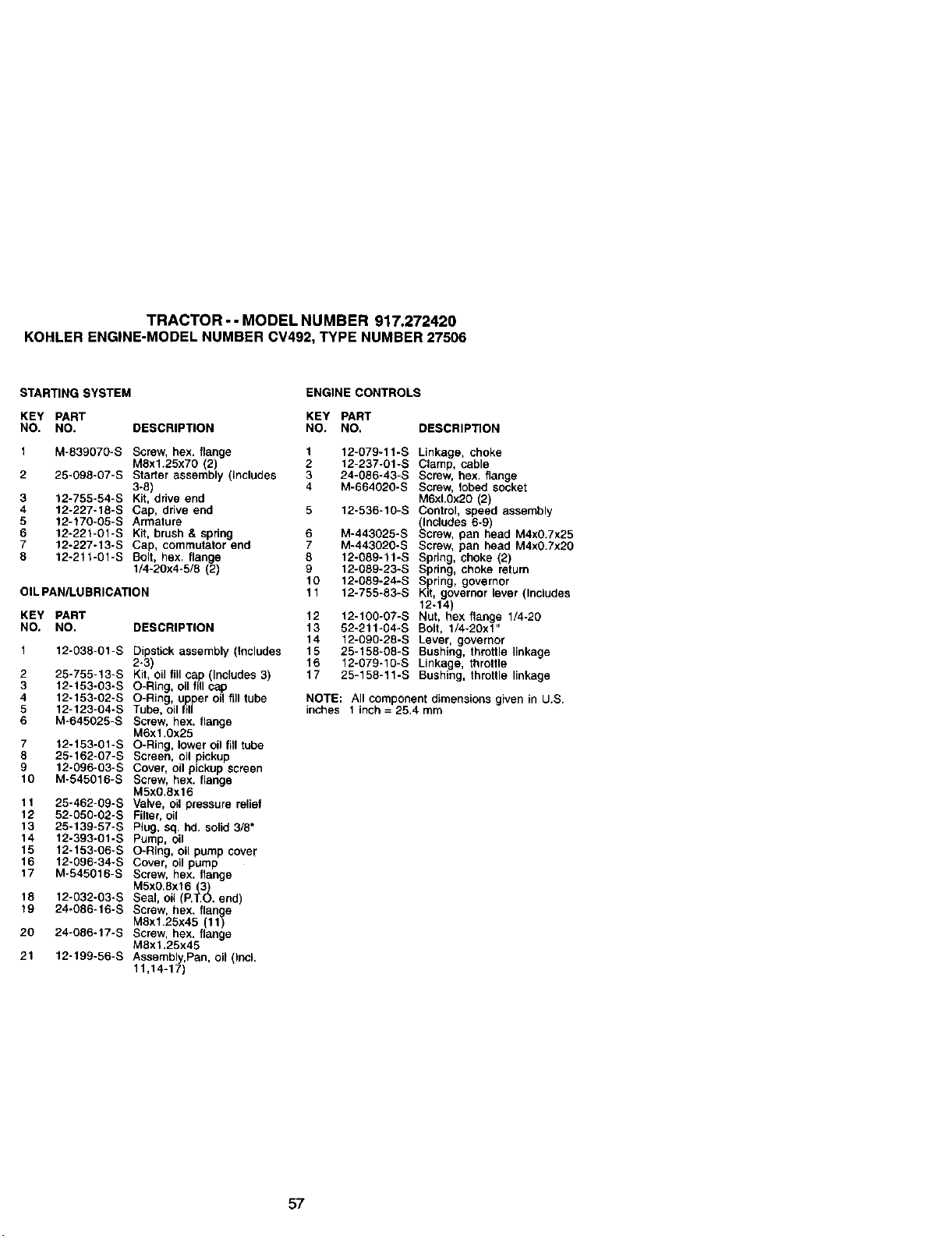
TRACTOR -- MODEL NUMBER 917.272420
KOHLER ENGINE-MODEL NUMBER CV492, TYPE NUMBER 27506
STARTING SYSTEM
ENGINE CONTROLS
KEY PART KEY PART
NO. NO. DESCRIPTION NO. NO, DESCRIPTION
1 M-839070-S Screw, hex. flange 1 12-079-11-S
M8x1.25x70 2 2 12-237-01-S
2 25-098-07-S Starter assereby ncudes 3 24-086-43-S
3-8) 4 M-664020-S
3 12-755-54-S Kit, drive end
4 12-227-18-S Cap, drive end 5 12-536-10-S
5 12-170-05-S Armature
6 12-221-01-S Kit, brush & spring 6 M-443025-S
7 12-227-13-S Cap, commutator end 7 M-443020-S
8 12-211-01-S Bolt hex. flange 8 12-089-11-S
1/4-20x4-5/8 2 9 12-089-23-S
10 12-089-24-S
12-755-83-S
OIL PAN/LUBRICATION 11
KEY PART
NO. NO. DESCRiPTiON
1 12-038-01-S Dipstick assembly (Includes
2-3)
2 25-755-13-S Kit, oil fill cap (Includes 3)
3 12-153-03-S O-Ring, oil fill cap
4 12-153-02-S O-Ring, upper oil fill tube
5 12-123-04-S Tube, oil fill
6 M-645025-S ScTew, hex. flange
M6x1.0x25
7 12-153-01-S O-Ring, lower oil fill tube
8 25-162-07-S Screen, oil pickup
9 12-09B-03-S Cover, oil pickup screen
10 M-545016-S Screw, hex. flange
M5x0.8x16
11 25-462-09-S Vah/e, oil pressure relief
12 52-050-02-S Filter,oil
13 25-139-57-S Plug, sq. hd, solid 3/8"
14 12-393-01-S Pump, oil
15 12-153-06-S O-Ring, oil pump cover
16 12-096-34-S Cover, oil pump
17 M-545016-S Screw, hex. flange
M5x0.8x16 _3)3
18 12-032-03-S Seal, oil (P._O. end)
19 24-086-16-S Screw, hex. flange
M8xl.25x45 (11)
20 24-086-17-S Screw, hex. flange
M8x1.25x45
21 12-199-56-S Assembly,Pan, oil (Incl.
11,14-17)
12 12-100-07-S
13 52-211-04-S
14 12-090-28-S
15 25-158-08-S
16 12-079-10-S
17 25-158-11-S
Linkage, choke
Clamp, cable
Screw, hex. flange
Screw, lobed socket
M6xL0x20 (2)
Control, speed assembly
(Includes 6-9)
Screw, pan head M4xO.7x25
Screw, pan head M4xO.7x20
Spring, choke (2)
Spring, choke return
Spring, governor
Kit, governor lever (Includes
12-14)
Nut, hex ran e 1/4-20
Bolt, 1/4-20x_"
Lever, governor
Bushing, throttle linkage
Linkage, throttle
Bushing, throttle {inkage
NOTE: All component dimensions given in U.S.
inches 1 inch = 25.4 mm
57
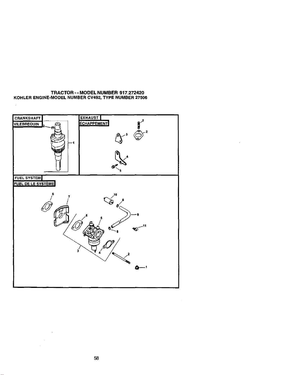
TRACTOR -- MODEL NUMBER 917.272420
KOHLER ENGINE-MODEL NUMBER CV492, TYPE NUMBER 27506
CRANKSHAFT J_
VILEBREQUIN I2_i i
FU EL SYSTEM J
'UEL DE LE SYSTEMEI
6
!
Dt
EXHAUST I
ECHAPPEMENT I
58
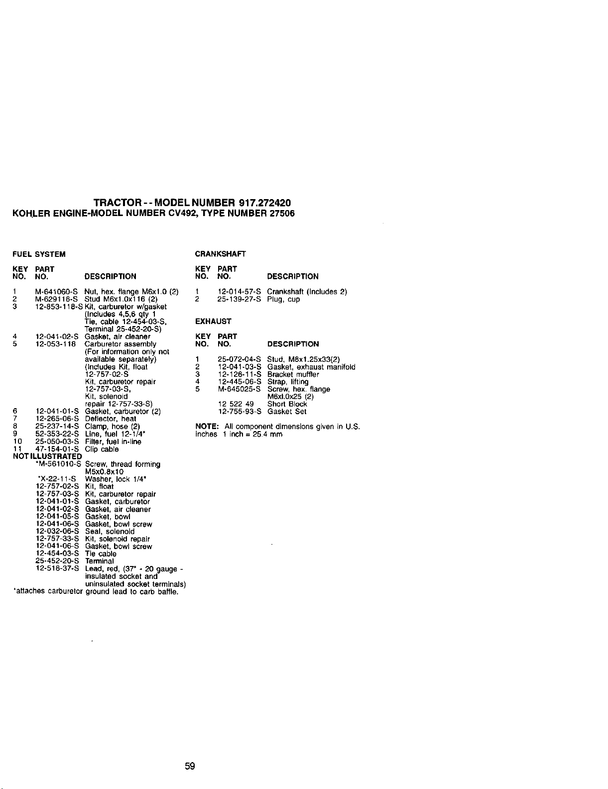
TRACTOR--MODELNUMBER917.272420
KOHLERENGINE-MODELNUMBERCV492,TYPENUMBER27506
FUEL SYSTEM
KEY PART
NO. NO. DESCRIPTION
1 M-641060-S Nut, hex. flange M6xl.0 (2)
2 M-629116-S Stud M6x1.Ox116 (2)
3 12-853-118-S Kit, carburetor w/gasket
(Includes 4,5,6 qty 1
Tie, cable 12.454-03-S,
Tsrmlnat 25-452-20-S)
4 12-041-02-S Gasket, air cleaner
5 12-053-118 Carburetor assembly
For information only not
ava abe separately)
_Ln¢_udesKit, float
12-757-02-S
Kit, carburetor repair
12-757-03-S,
Kit, solenoid
repair 12-757-33-S)
6 12-041-01-S Gasket, carburetor (2)
7 12-265-06-S Deflector, heat
8 25-237-14-S Clamp, hose (2)
9 52-353-22-S Line, fuel 12-f/4"
10 25-050-03-S Filter, fuel in.line
1t 47-_54-01-S C_ip cable
NOT ILLUSTRATED
*M-561010-S Screw, thread forming
M5xO.8xlO
*X-22-11-S Washer, lock 1/4"
12-757-02-S Kit, float
12-757-03-S Kit, carburetor repair
12-041-01-S Gasket, carburetor
12-041-02-S Gasket, air cleaner
12-041-05-S Gasket, bowl
12-041-06-S Gasket, bowl screw
12-032-06-S Seal, solenoid
12-757-33-S Kit, solenoid repair
12-041-06-S Gasket, bow[ screw
12-454-03-S Tie cable
25-452-20-S Terminal
12-518-37-S Lead, red, 37"- 20g
insu ated socket and auge
uninsulated socket terminals)
"attaches carburetor ground lead to carb baffle.
CRANKSHAFT
KEY PART
NO. NO. DESCRIPTION
I 12-014-57-S Crankshaft (Includes 2)
2 25-139-27-S Plug, cup
EXHAUST
KEY PART
NO. NO. DESCRIPTION
1 25-072-04-S Stud, M8xl.25x33(2)
2 12-041-03-S Gasket, exhaust manifold
3 12-126-11-S Bracket muffler
4 12-445-06-S Strap, lifting
5 M-645025-S Screw, hex. flange
M6xL0x25 (2)
12 522 49 Shod Block
12-755-93-S Gasket Set
NOTE: All component dimensions given in U.S.
inches 1 inch = 25.4 mm
59

SERVICE NOTES
6O

SERVICE NOTES
61

SERVICE NOTES
62
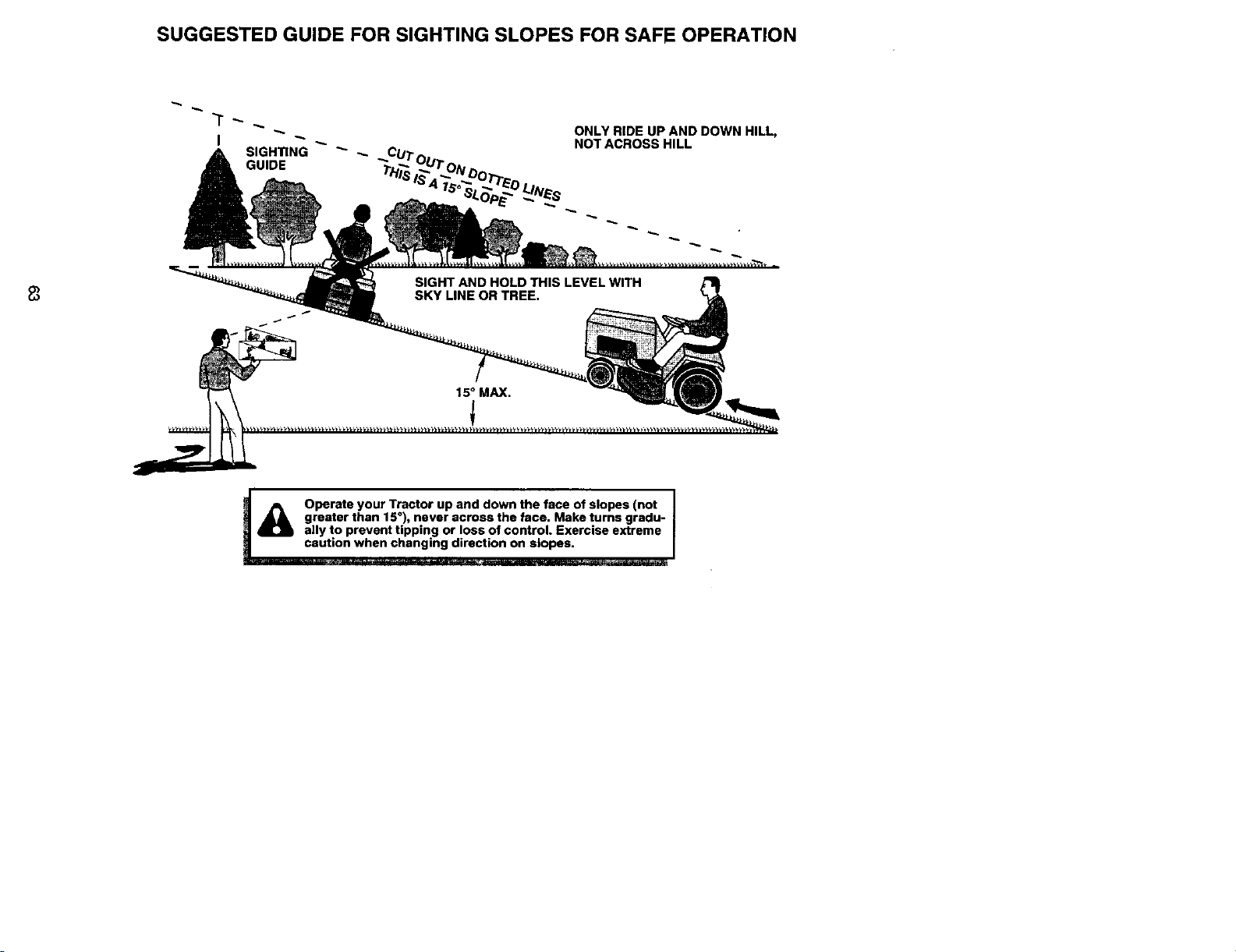
SUGGESTED GUIDE FOR SIGHTING SLOPES FOR SAFE OPERATION
ONLY RIDE UP AND DOWN HILL,
NOT ACROSS HILL
t_ ca/_ Operate your Tractor up and down the face of slopes (not I
I
_U_ greater than 15°), never across the face. Make turns gradu-
f
O ally to prevent tipping or loss of control. Exercise extreme
ution when changing direction on slopes.

Get itfixed, at your home or ours!
Forrepairofmajor brandappliancesin your own home, ..
no matterwhomade it,nomatterwho soldit!
1-800-4-MY-HOME _ Any_ dayornigtlt
(1_) (U.S.A.and Canada)
wY/iN.seal_.corll '_lt/W._6_ELC_I
Forrepair ofcarry-inproducts like vacuums,lawnequipment,ar_
electronics,call forthenearestSears Parts and Repair Center.
1-800-488-1222 /u_rne,dayorright(U.SA.only)
www.sear_corn
Forthe replacement parts,accassoriesand owner's manuals
that you need to do-it-yourseff,callSears ParLsDirectSM!
1-800-366-PART
(1-80o-366-7278)
6 a.m.- 11p.m., 7days aweeK
(u.s.A.o,_)
To purchase orinquireabouta SearsServiceAgreement
orSears Maintenance Agreement:.
1-800-827-6655 (u.s.A.) 1-800-361-6665 (Canada)
7am.-S p.m.,CST,IVk_,-Sat. 9a.m.-8p.m.EST,M- F,4p.m.Sat.
Parapedrserviciodemparack_a
_onicJo,y paraordenaroiezas:
1-888-SU.HOGARsM
(1.-888-784_27)
AuCanadapoursewiceen_ar_:
1-8004.E-FOYERMc
(1-800-5,33-6937)
www.ssars,ca
® Registered Trademark / TMTrademark / suService Mark of Seam, Roebuck and Co.
® Marca Registrada / TMMarca de Fabdca / SMMarca de Sewicio de Sears, Roebuck and Co,
MCMarque de commerce / _o Marque d_posde de Sears, Roebuck and Co,
177411 02.28.01 RH Printed in U.S.A.