
Loading ...
Loading ...
Loading ...
10
Wiring
OPTIONAL CONNECTIONS (cont’d)
VOICE BOARD OPTION
The voice board provides one of two verbal warnings that the fire door
is closing. Typically, depending on the length of the delay chosen on the
release device, a warning tone will occur prior to the message, which
is approximately 10 seconds in length (for example, a 20 second delay
setting on the release device will result in a 10 second warning tone
followed by the verbal warning message). There are two messages that
may be selected:
Message 1: Warning tone followed by the message, “Warning! An
emergency condition exists and this fire door is about to close;
please remove any obstructions from its path and stand clear.”
Message 2: Warning tone followed by the message, “Warning!
This fire door will close in 10 seconds... 5 seconds... the fire door
is now closing; please remove any obstructions from its path and
stand clear.”
The release device has an 4-position DIP Switch mounted on the
circuit board, and the switch at position #3 permits selection of either
message. In the “ON” position, Message 1 is activated; in the “OFF”
position, Message 2 is activated (Figure 12).
The voice board can drive up to two 70.7V speakers (Model LMSP24R)
or speaker inputs to speaker strobes (Model LMSS24R). Maximum
delivered power is 5 watts.
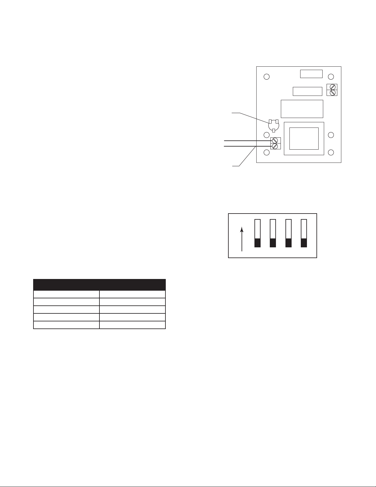
A potentiometer (VR1) is mounted on the board and rotation
counterclockwise increases the volume (clockwise to decrease volume)
(Figure 11).
DIP SWITCH SELECTION
The release device will provide a factory default delay of 10 seconds (to
minimize nuisance alarms) before releasing the fusible link chain upon
alarm or power loss. A 4-position DIP Switch found on the PC board
within the release device can be used to adjust the length of the delay to
one of four preset delays.
The optional delay settings are as follows:
NOTE: Set all DIP switch options before applying power to the system.
1 2
10 Seconds Off Off
20 Seconds Off On
30 Seconds On Off
60 Seconds On On
Delay Settings Switch Position
Figure 11
Figure 12
Wire to Speaker
Volume Control
CCW for Max
1 2 3 4
ON
NOTE: Position 4 is unused and should remain in the OFF position.
Position 3 is used to select one of the two available voice messages.
Factory default setting of 10 seconds shown.
Loading ...
Loading ...
Loading ...