Loading ...
Loading ...
Loading ...
COMPACT CASSETTE TECHNICAL OVERVIEW
D-6
ENGLISH
Testing
Indoor Fan Motor Test Procedure
If the indoor fan motor does not run:
1. Disconnect power to the system.
2. Remove the return air cover and access the circuit board connection.
3. Reset power and turn the remote control fan command to Fan On mode.
Testing Temperature Sensors
The easiest problems to solve will involve codes that are related to potential failure of temperature sensors. Common problems
may include loose connections, open electrically, and out of calibration. Checking the condition of the sensors requires a
temperature probe and an ohmmeter.
The Reference Section of this manual contains temperature resistance tables that can be used to check the calibration of the
sensors. The measured resistance must be within the tolerances printed on the top of the tables.
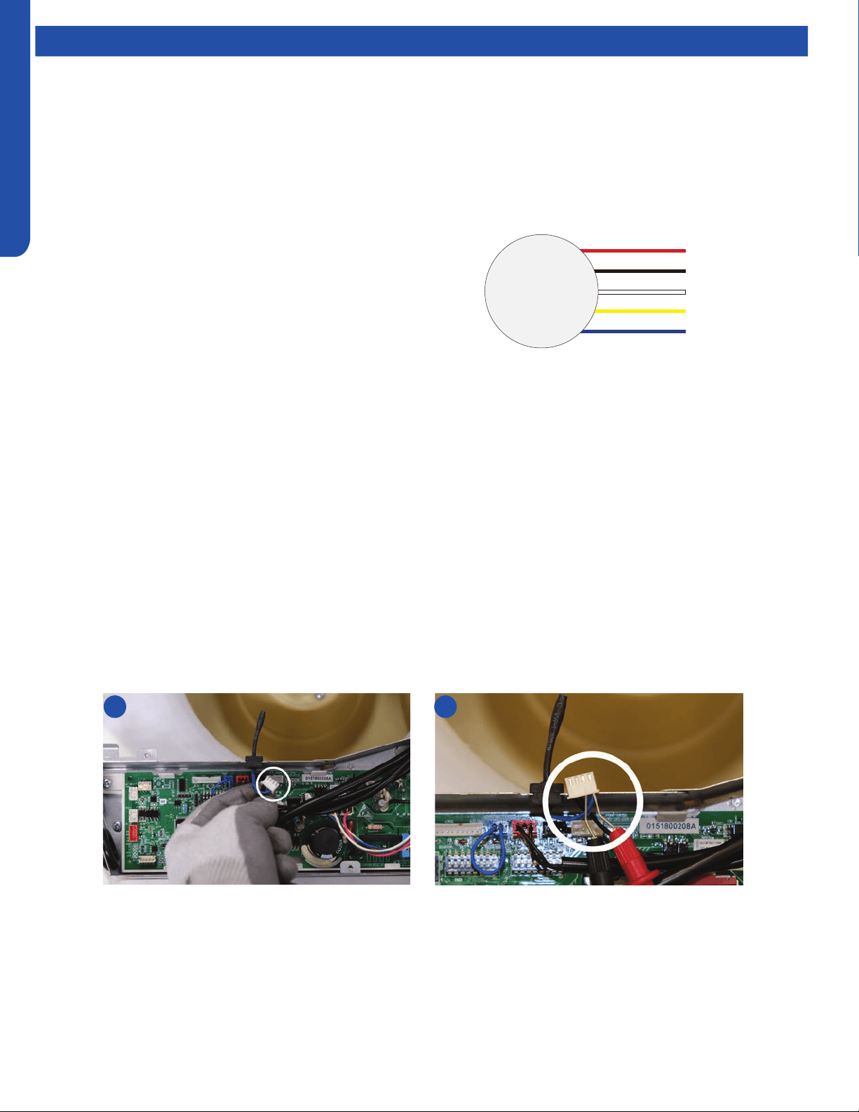
To test the electrical condition of a temperature sensor perform the following:
1. Conrm the sensor is rmly attached to the circuit board connection plug.
2. Remove the sensor wires form the connection plug by releasing holding tension on the plugs tension tab.
3. Use an ohmmeter to test the electrical resistance of the sensor.
4. Measure the air temperature near the sensor and compare the required resistance against measured resistance. (See chart in
reference section) If the sensor is within calibration, the sensor is good. If the sensor is out of calibration, replace the sensor.
(Tube Sensors should be removed from socket and exposed to air temperature during test.)
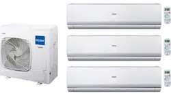
Motor Test:
1. If the motor doesn’t run, check for 310VDC between Pins 1
and 3. If it is not present, the indoor board is bad. If voltage
is present, continue on.
2. Check the voltage between Pins 3 and 4. The voltage
should be +15VDC. If it is not present, the board is bad. If
voltage is present, continue on.
3. Check for voltage between Pins 3 and 6. If no DC voltage
is present, the board is bad. If voltage is present, change
the motor.
2 4
DC Motor
+310 VDC
DC Ground
+15 VDC
Signal
Feedback
Red
Black
White
Yellow
Blue
Loading ...
Loading ...
Loading ...