Loading ...
Loading ...
Loading ...
12
M6000-01 • 04/16/12 • Casablanca Fan Company
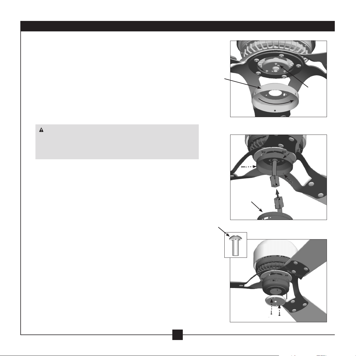
7 • Installing the Switch Housing
12
7-1. To attach the upper switch housing, partially install two housing
assembly screws into the switch housing mounting plate.
7-2. Feed the upper plug connector through the center opening of
the housing.
7-3. Align the keyhole slots in the housing with the housing
assembly screws.
7-4. Turn the housing counterclockwise until the housing assembly
screws are rmly situated in the narrow end of the keyhole
slots. Install the remaining screw into the housing. Tighten all
three screws rmly.
CAUTION: Make sure the upper switch housing is securely
attached to the switch housing mounting plate. Failure to properly
attach and tighten all three assembly screws could result in the
switch housing xture falling.
7-5. To attach the lower switch housing, connect the upper plug
connector from the motor to the lower plug connector in the
lower switch housing.
Note: Both plug connectors are polarized and will only t
together one way. Make sure the connectors are properly
aligned before connecting them. Incorrect connection could
cause improper operation and damage the product.
7-6. Place the lower switch housing assembly over the upper
switch housing. Align the side screw holes in the upper and
lower switch housings. Attach the lower switch housing to the
upper switch housing with three housing assembly screws.
Note: You can customize your Casablanca fan with a number
of accessory light kits. To install an optional light kit, remove
the logo cap by removing the two screws located on the inside
of the lower switch housing.
7-7. Use the optional switch housing cap to attach light kits
that mount using a center stem attachment. Follow the
instructions included with the light kit for the wiring,
mounting, and assembly.
Steps 7-1 – 7-4
Housing
Assembly
Screw
Housing
Assembly
Screw
Upper
Switch
Housing
Lower
Switch
Housing
Steps 7-5 – 7-6
Step 7-7
Loading ...
Loading ...
Loading ...