Questions?/ Des questions?/ ¿Preguntas? 1-800-334-6871 [email protected]
1
Instruction Manual / Manuel d’instructions/ Instrucciones
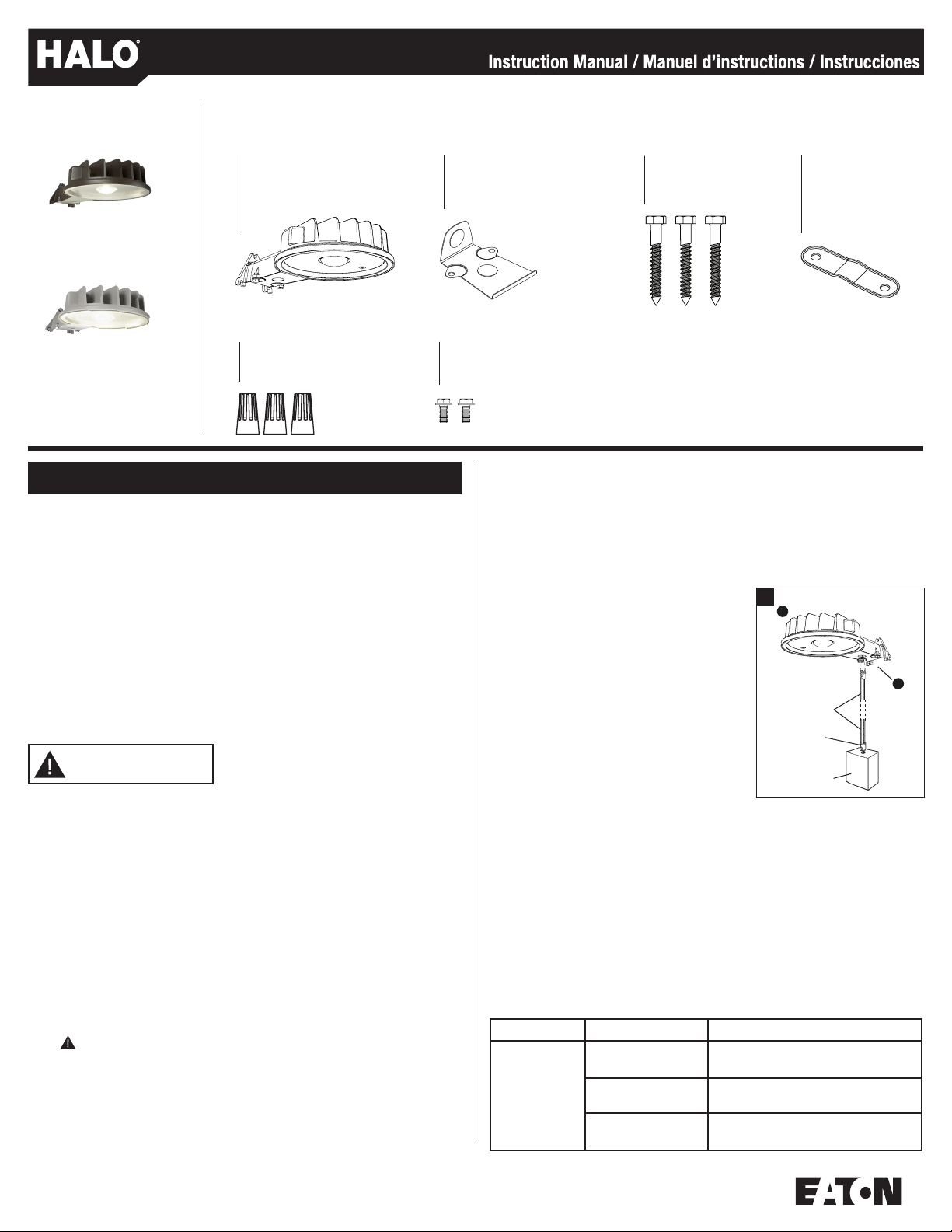
PACKAGING CONTENTS /CONTENU DE L’EMBALLAGE/CONTENIDO DEL PAQUETE
®
1. Turn off the power at the main fuse/breaker box.
2. Using the pattern on the box, mark and drill holes for mounting.
NOTE: Mount this fixture in an upright and level position.
3. Install the two bottom mounting screws (C) first, leaving enough room between the
mounting screws and the mounting surface to accommodate mounting the fixture.
4. Screw the top mounting screw (C) into the predrilled hole and back the screw out. This
will leave the hole threaded and make installation of the fixture easier.
5. Remove cover plate by loosening the two screws inside the cover plate. Do not remove
the screw.
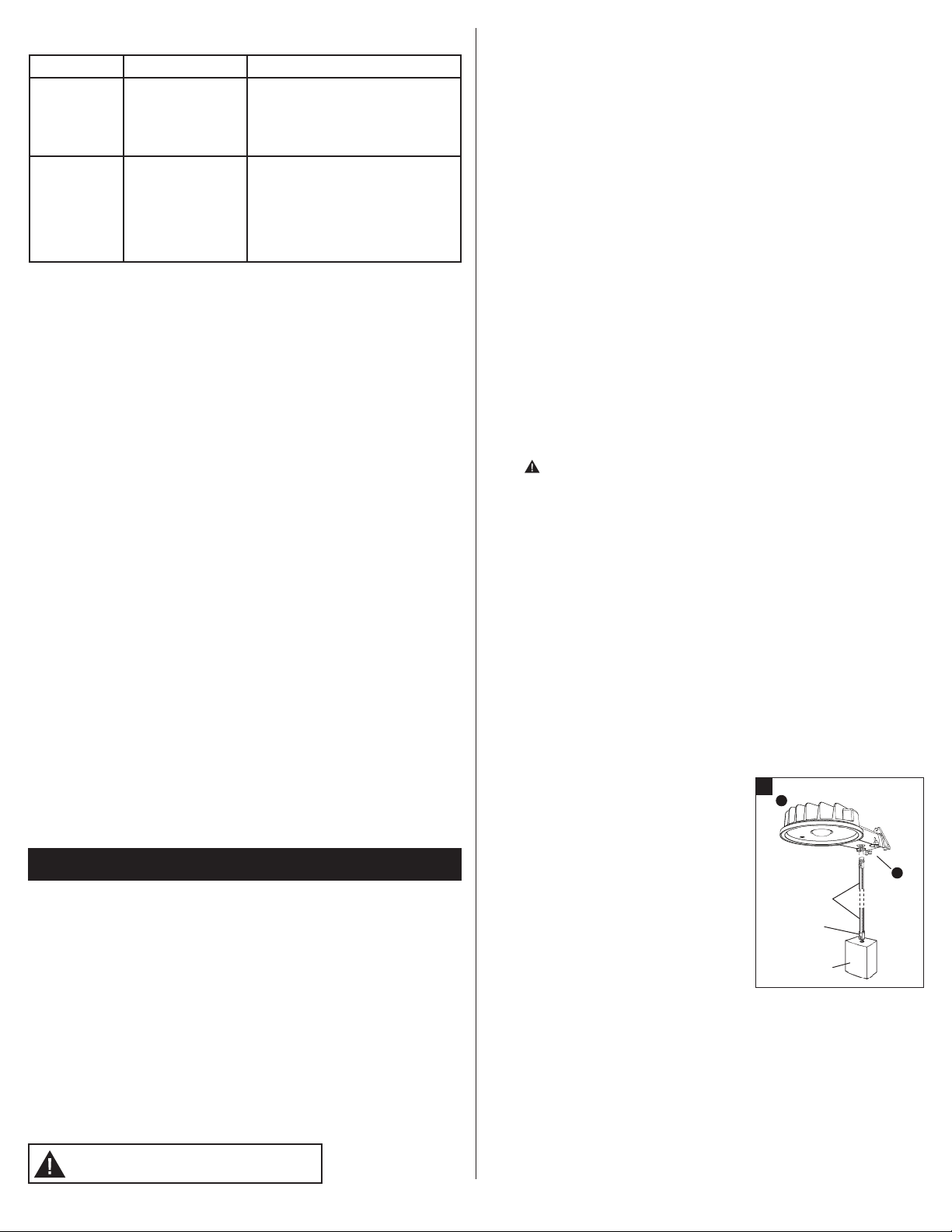
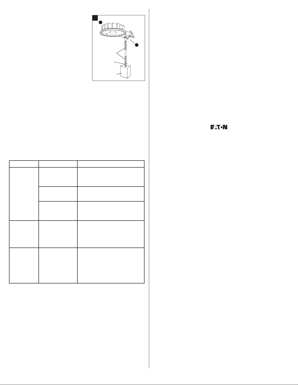
6. Remove access cover (B) from fixture (A). Install
the first conduit connector and conduit (sold
separately) into the access cover (B) (Fig. 1).
7. Feed supply wires into conduit. Attach ground wire
that is attached to fixture housing (A) to the junction
box earth ground wire.
8. Connect the black fixture wire to the black supply
wire (hot) with UL-approved wire connector (E).
Connect the white fixture wire to the white supply
wire (neutral) with UL-approved wire connector (E).
NOTE: Be careful to connect the wires correctly.
Make sure no bare strands of wire extend from the
wire nut or other approved wire connectors (E).
9. Attach access cover (B) to the light fixture (A)
using the two access cover mounting screws
provided (F) (Fig. 1).
NOTE: Make sure all wiring is placed into the arm prior to tightening the access
cover screws.
10. Place the fixture (A) on the two lower mounting screws (C) and install the upper mounting
screw (C). Tighten all mounting screws to secure the fixture (A).
11. Reinstall the cover plate, making sure to tighten the two screws to secure the lens to the
fixture (A)
12. Connect second conduit and conduit connector at the junction box (Fig. 1).
NOTE: This fixture can be mounted on 1-5/8 in. diameter extension arms (sold separately).
When installing fixture onto an extension arm, remove the access cover (B) and use the
included pole mounting clamp (D) and access cover mounting screws (F).
13. Turn power back ON
ITEMS REQUIRED
(Purchase separately)
• Phillips screwdriver
• Adjustable wrench or ratchet wrench with 10mm socket
• Drill with 3/16 in. drill bit
• 1/2 in. diameter conduit (if applicable, length depends on application)
• 1/2 in. watertight conduit connectors (if applicable)
• Wire connectors
IMPORTANT SAFETY INSTRUCTIONS
When using product, basic precautions should always be followed, including the following:
• Heed all warnings, including below warnings AND those included on product.
• Save these instructions and warnings.
• For outdoor use only.
• cULus LISTED for wet location use.
• Read and follow these instructions.
• Disconnect at fuse or circuit breaker before installing or servicing.
• Edges may cut. Handle with care.
CAUTION
• Connect fixture to a 120 volt, 60 Hz power source. Any other connection voids
the warranty.
• Fixture should be installed by persons with experience in household wiring or by a
qualified electrician. The electrical system, and the method of electrically connecting
the fixture to it, must be in accordance with the National Electrical Code and local
building codes.
• Upside down installation can result in overheating or accumulation of water in fixture.
Install right side up.
• This device complies with Part 15 of the FCC Rules. Operation is subject to the
following two conditions: (1) This device may not cause harmful interference, and (2)
this device must accept any interference received, including interference that may cause
undesired operation
WARNING: FCC Regulations state that any unauthorized changes or
modifications to this equipment not expressly approved by the manufacturer
could void the user’s authorization to operate this equipment.
SAVE THESE INSTRUCTIONS.
MOUNTING AND WIRING YOUR FIXTURE
NOTE: This fixture is intended to be conduit connected to a properly installed and properly
grounded metal weatherproof junction box (not included). All conduit connectors, conduit, and
junction boxes (sold separately) should be cULus Listed suitable for wet locations.
ENGLISH
WARNING
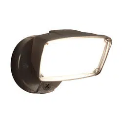
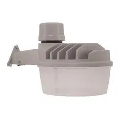
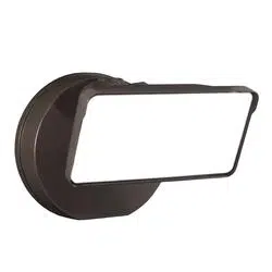
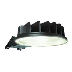
A. Light fixture
Appareil d’éclairage
Accesorio
B. Access cover
Cache d’accès
Cubierta de acceso
C. (3) Mounting screws
(3)Vis de montage
(3) Tornillos de montaje
D. Pole mounting clamp
Patte pour montage
sur bras
Abrazaderapara
montajede poste
E. (3) Wire connectors
(3) Capuchons de connexion
(3) Conectores de cables
F. (2) Access cover mounting screws
(2) Vis de montage du cache d’accès
(2) Tornillos de la cubierta de acceso
AL4850LPCBZ
(Bronze/Bronze/ Bronce)
AL4850LPCGY
(Gray/ Gris/ Gris)
Problem Cause Solution
Light does not
come on or
light comes
on for only a
few seconds.
No power to the fixture. • Check if circuit breaker tripped.
• Confirm wall switch is ON.
Light sensor is not
working properly.
• Check if light is being reflected into the
sensor, causing the fixture to turn off.
Wiring to the unit
is loose.
TURN OFF POWER BEFORE CONTINUING.
• Confirm wiring is properly secured.
TROUBLESHOOTING
1
Conduit
Conduit
connector
Junction
B
A
B
2
FRANÇAIS
5-YEAR LIMITED WARRANTY
THE FOLLOWING WARRANTY IS EXCLUSIVE AND IN LIEU OF ALL OTHER WARRANTIES,
WHETHER EXPRESS, IMPLIED OR STATUTORY INCLUDING, BUT NOT LIMITED TO, ANY
WARRANTY OF MERCHANTABILITY OR FITNESS FOR ANY PARTICULAR PURPOSE.
Eaton warrants to customers that, for a period of five years from the date of purchase, Eaton
products will be free from defects in materials and workmanship. The obligation of Eaton
under this warranty is expressly limited to the provision of replacement products. This
warranty is extended only to the original purchaser of the product. A purchaser’s receipt or
other proof of date of original purchase acceptable to Eaton. This is required before warranty
performance shall be rendered. This warranty does not apply to Eaton products that have been
altered or repaired that have been subjected to neglect, abuse, misuse or accident
(including shipping damages). This warranty does not apply to products not manufactured by
Eaton which have been supplied, installed, and/or used in conjunction with Eaton products.
Damage to the product caused by replacement bulbs or corrosion or discoloration of brass
components are not covered by this warranty.
LIMITATION OF LIABILITY:
IN NO EVENT SHALL EATON BE LIABLE FOR SPECIAL, INDIRECT, INCIDENTAL, OR
CONSEQUENTIAL DAMAGES (REGARDLESS OF THE FORM OF ACTION, WHETHER IN CONTRACT,
STRICT LIABILITY, OR IN TORT INCLUDING NEGLIGENCE), NOR FOR LOST PROFITS; NOR SHALL
THE LIABILITY OF EATON FOR ANY CLAIMS OR DAMAGE ARISING OUT OF OR CONNECTED
WITH THESE TERMS OR THE MANUFACTURE, SALE, DELIVERY, USE, MAINTENANCE, REPAIR OR
MODIFICATION OF COOPER LIGHTING PRODUCTS, OR SUPPLY OF ANY REPLACEMENT PARTS
THEREFORE, EXCEED THE PURCHASE PRICE OF EATON PRODUCTS GIVING RISE TO A CLAIM. NO
LABOR CHARGES WILL BE ACCEPTED TO REMOVE OR INSTALL FIXTURES.
To obtain warranty service, please contact Eaton at 1-800-334-6871, press option 2 for
Customer Service, or via e-mail [email protected] and include the following
information:
• Name, address and telephone number
• Date and place of purchase
• Catalog and quantity purchase
• Detailed description of problem
All returned products must be accompanied by a Return Goods Authorization Number issued
by the Company and must be returned freight prepaid. Any product received without a Return
Goods Authorization Number from the Company will be refused. Eaton is not responsible for
merchandise damaged in transit. Repaired or replaced products shall be subject to the terms
of this warranty and are inspected when packed. Evident or concealed damage that is made
in transit should be reported at once to the carrier making the delivery and a claim filed with
them.
Reproductions of this document without prior written approval of Eaton are strictly prohibited.
For assistance, call 1-800-334-6871 or e-mail us at [email protected]
Printed in China
TROUBLESHOOTING
Problem Cause Solution
Light does not
shut off during
daytime.
Light sensor is not
receiving enough light
to trigger switch.
• Shine a flashlight into the light sensor for
2-3 minutes. The fixture should switch
off after two minutes. This means the
sensor is not receiving enough light;
reposition or relocate the fixture.
Light cycles on
and off.
Light sensor is sensing
reflected light.
• Cover light sensor with a piece of black
electrical tape. The fixture should turn
on after a slight delay. This means that
extraneous or reflected light from the
fixture is causing the sensor to turn the
unit off. Install fixture where there is no
reflective light.
ARTICLES REQUIS :
(à acheter séparément)
• Tournevis cruciforme
• Clé à molette ou clé à rochet avec douille de 10mm
• Perceuse avec foret de 3/16po
• Conduit d’un diamètre de 1/2po (au besoin, longueur selon l’installation)
• Raccords de conduit étanches de 1/2po (au besoin)
• Capuchons de connexion
IMPORTANTES INSTRUCTIONS DE SÉCURITÉ
Des précautions de base doivent être suivies lors de l’utilisation de ce produit, incluant :
• Le respect de tous les avertissements incluant les avertissements ci-dessous
ET ceux indiqués sur le produit.
• Conservez ces instructions et ces avertissements.
• Exclusivement réservé à un usage extérieur.
• Homologation cULus pour l’utilisation dans des endroits humides.
AVERTISSEMENT
• Lisez et suivez ces instructions.
• Coupez l’alimentation électrique au fusible ou au disjoncteur avant l’installation
ou l’entretien.
• Les bords peuvent être coupants. Manipuler avec soin.
MISE EN GARDE
• Raccordez le luminaire à une source d’alimentation de 120 V, 60 Hz.
Tout autre raccordement annule la garantie.
• L’appareil d’éclairage doit être installé par des personnes ayant l’expérience du
câblage domestique ou par un électricien qualifié. Le système électrique et la méthode
de raccordement électrique de l’appareil d’éclairage doivent être conformes au Code
national de l’électricité et aux codes locaux du bâtiment.
• Si l’appareil d’éclairage est installé à l’envers, il peut y avoir surchauffe ou
accumulation d’eau. Installez-le à l’endroit.
• Après la mise à l’essai, cet équipement a été déclaré conforme aux limites établies
pour un dispositif numérique de catégorieB en vertu de la section 15 des règlements
de la FCC. Ces limites sont conçues pour assurer une protection raisonnable
contre toute interférence nuisible dans une installation résidentielle. Cet équipement
génère, utilise et dégage de l’énergie radiofréquence. S’il n’est pas installé et utilisé
conformément aux instructions, il est susceptible de créer des interférences nuisibles
aux communications radio. Toutefois, il n’est absolument pas garanti qu’aucune
interférence ne se produira dans une installation donnée. Si l’équipement crée
des interférences nuisibles à la réception d’émissions de radio ou de télévision (pour le
savoir, allumez-le et éteignez-le), il est conseillé à l’utilisateur d’essayer d’éliminer ces
interférences en adoptant une ou plusieurs des mesures suivantes:
- Réorientez ou déplacez l’antenne réceptrice.
- Augmentez la distance entre l’équipement et le récepteur.
- Branchez l’équipement sur la prise électrique d’un circuit autre que celui sur lequel
le récepteur est branché.
- Demandez de l’aide au distributeur ou à un technicien radio ou TV qualifié.
AVERTISSEMENT : Les réglementations de la FCC mentionnent que toute
modification ou altération apportée à cet équipement n’étant pas expressément
approuvée par le fabricant peut annuler le droit de l’utilisateur à faire
fonctionner cet équipement.
CONSERVEZ CES INSTRUCTIONS.
MONTAGE ET CÂBLAGE DE L’APPAREIL D’ÉCLAIRAGE
REMARQUE : Cet appareil d’éclairage a été conçu pour le raccordement en conduit à un
boîtier de jonction en métal étanche, mis à la terre et adéquatement installé (non inclus).
Tous les conduits, raccords et boîtiers de jonction (vendus séparément) doivent posséder
l’homologation cULus pour l’utilisation dans des endroits humides.
1. Coupez le courant à la boîte de fusibles ou de disjoncteurs principale.
2. À l’aide du gabarit du boîtier, marquez et percez les trous de montage.
REMARQUE : Cet appareil d’éclairage doit être installé en position verticale et de niveau.
3. Installez d’abord les 2 vis de montage du bas (C), en laissant assez d’espace pour
l’appareil d’éclairage jusqu’à la surface de montage.
4. Vissez la vis de montage du haut (C) dans le trou prépercé, puis dévissez-la.
Cette mesure vise à fileter le trou pour faciliter l’installation de l’appareil d’éclairage.
5. Retirez la plaque de recouvrement en desserrant les deux vis à l’intérieur de la plaque de
recouvrement. Ne retirez pas la vis.
6. Retirez le cache d’accès (B) de l’appareil
d’éclairage (A). Installez le premier raccord
de conduit et le conduit (vendus séparément)
dans le cache d’accès (B) (fig.1).
7. Passez les fils d’alimentation dans le conduit.
Raccordez le fil de terre fixé au logement
de l’appareil d’éclairage (A) au fil de mise à la
terre du boîtier de jonction.
8. Raccordez le fil noir de l’appareil d’éclairage au
fil noir de l’alimentation (sous tension) à l’aide
d’un capuchon de connexion homologué UL (E).
Raccordez le fil blanc de l’appareil d’éclairage
au fil blanc de l’alimentation (neutre) à l’aide
d’un capuchon de connexion homologué UL (E).
REMARQUE : Prenez soin de bien raccorder les
fils. Vérifiez qu’aucun brin dénudé ne sort des
capuchons de connexion fournis ou d’autres
capuchons de connexion approuvés (E).
9. Fixez le cache d’accès (B) à l’appareil d’éclairage
(A) à l’aide des 2 vis de montage du cache d’accès fournies (F) (fig.1).
REMARQUE : Avant de serrer les vis du cache d’accès, vérifiez que vous avez
passé tous les fils dans le bras.
10. Placez l’appareil d’éclairage (A) sur les deux vis de montage du bas (C),
et posez la vis de montage du haut(C). Serrez toutes les vis de montage pour
bien fixer l’appareil d’éclairage (A).
11. Réinstallez la plaque de protection en veillant à bien serrer les deux vis pour fixer l’objectif
à la fixation (A).
1
Conduit
Conduit
connector
Junction
B
A
B
3
12. Raccordez le deuxième conduit et le raccord de conduit au boîtier de jonction (fig. 1).
REMARQUE : Il est possible de monter cet appareil d’éclairage sur un bras de 4,1cm
(1-5/8po) de diamètre (vendu séparément). Dans ce cas, retirez le cache d’accès (B) et
utilisez la patte pour montage sur bras (D) et les vis de montage du cache d’accès (F).
13. Rétablissez l’alimentation.
DÉPANNAGE
GARANTIE LIMITÉE DE 5 ANS
LA PRÉSENTE GARANTIE CONSTITUE LA SEULE GARANTIE POUR CE PRODUIT ET PRÉVAUT
SUR TOUTE AUTRE GARANTIE, QU’ELLE SOIT EXPRESSE OU TACITE Y COMPRIS, SANS
TOUTEFOIS S’Y LIMITER, TOUTE GARANTIE DE QUALITÉ MARCHANDE ET POUR UN USAGE
PARTICULIER.
Eaton garantit à ses clients, pendant une période de cinq ans à compter de la date d’achat,
que ses produits Eaton sont exempts de tout défaut de matériaux et de fabrication. En vertu
de la présente garantie, l’obligation de Eaton se limite expressément à fournir des produits de
remplacement. La présente garantie n’est proposée qu’à l’acheteur initial du produit. Eaton
requiert un reçu ou autre preuve d’achat qu’elle jugera acceptable sur lequel est indiquée la
date de l’achat initial. Cette preuve d’achat est requise pour obtenir l’exécution de la garantie.
La garantie ne s’applique pas aux produits Eaton qui ont été modifiés ou réparés, ou qui ont
fait l’objet d’une négligence ou d’un usage abusif ou inapproprié, ou qui ont été endommagés
en raison d’un accident (y compris durant le transport). Cette garantie ne s’applique pas aux
produits qui ne sont pas fabriqués par Eaton et qui ont été fournis, installés et/ou utilisés avec
des produits Eaton. Les dommages au produit causés par une ampoule de rechange ou la
corrosion, et la décoloration des pièces de laiton ne sont pas couverts par cette garantie.
LIMITATION DES RESPONSABILITÉS :
EATON NE SERA EN AUCUN CAS TENU RESPONSABLE DES DOMMAGES SPÉCIAUX, INDIRECTS,
ACCESSOIRES ET CONSÉCUTIFS (QUELLE QUE SOIT LA RAISON, MÊME SI CETTE
RESPONSABILITÉ REPOSE SUR UN CONTRAT, LA RESPONSABILITÉ STRICTE, OU DES DÉLITS, Y
COMPRIS LA NÉGLIGENCE), NI POUR LA PERTE DE PROFITS, ET MÊME SI LA RESPONSABILITÉ
DE EATON POUR DES RÉCLAMATIONS OU DES DOMMAGES FAIT SUITE À LA PRÉSENTE
GARANTIE OU EST LIÉE AUX MODALITÉS DES PRÉSENTES, À LA FABRICATION, À LA VENTE,
À LA LIVRAISON, À L’UTILISATION, À L’ENTRETIEN, À LA RÉPARATION, OU À LA MODIFICATION
DE PRODUITS EATON, OU À LA FOURNITURE DE TOUTE PIÈCE DE RECHANGE CONNEXE, LE
COÛT DES DOMMAGES NE PEUT DÉPASSER LE COÛT D’ACHAT DU PRODUIT EATON FAISANT
L’OBJET DE LA RÉCLAMATION AU TITRE DE LA PRÉSENTE GARANTIE. AUCUN FRAIS DE MAIN-
D’OEUVRE NE SERA REMBOURSÉ POUR ENLEVER OU INSTALLER UN LUMINAIRE.
Pour faire une réclamation au titre de la garantie, veuillez appeler Eaton, au 1 800 334 6871,
en choisissant l’option 2 pour le Service à la clientèle, ou envoyer un courriel à Consumer-
[email protected] et fournir les renseignements ci-après :
• Nom, adresse et numéro de téléphone
• Date et lieu de l’achat
• Numéro de catalogue et quantité achetée
• Description détaillée du problème
Tout produit retourné doit comporter un numéro d’autorisation de retour de produit fourni par
l’entreprise et être expédié port payé. Nous refuserons tout produit qui n’est pas
accompagné d’un numéro d’autorisation de retour de produit fourni par l’entreprise. Eaton
n’est pas responsable de la marchandise endommagée durant le transport. Les produits
réparés ou remplacés seront soumis aux modalités de la présente garantie et seront inspectés
au moment d’être emballés. Tout dommage apparent ou non survenant pendant le transport
doit être signalé immédiatement au transporteur effectuant la livraison et une réclamation
doit être adressée à ce dernier. La reproduction de ce document est strictement interdite sans
Problème Cause Solution
La lampe ne
s'allume pas
ou ne s'allume
que quelques
secondes.
Aucune tension n'arrive
à l'appareil d'éclairage.
• Vérifiez si le disjoncteur du circuit s'est
déclenché.
• Vérifiez que l'interrupteur mural est bien
allumé.
Le capteur fonctionne
mal.
• Vérifiez si une lumière se réfléchit dans
le capteur et déclenche l'extinction de
l'appareil d'éclairage.
Des fils de l'appareil
sont desserrés.
COUPEZ L'ALIMENTATION AVANT DE
POURSUIVRE.
• S'assurer que le câblage est installé
correctement.
La lampe ne
s'éteint pas
pendant la
journée.
Le capteur de
luminosité ne reçoit
pas suffisamment
de lumière pour que
l'interrupteur se
déclenche.
• Allumez une lampe de poche devant
le capteur de luminosité pendant 2 à
3minutes. L'appareil d'éclairage devrait
s'éteindre au bout de 2minutes. Si c'est le
cas, le capteur ne reçoit pas suffisamment
de lumière. Repositionnez ou déplacez
l'appareil d'éclairage.
La lampe
s'allume
et s'éteint
continuellement.
Le capteur de
luminosité détecte la
lumière réfléchie.
• Recouvrez le capteur de luminosité
de ruban noir d'électricien. L'appareil
d'éclairage devrait s'allumer après un court
instant. Dans ce cas, la lumière extérieure
ou réfléchie par l'appareil déclenche
l'extinction de la lampe par le capteur.
Installer la lampe dans un endroit ne
réfléchissant pas la lumière.
ARTÍCULOS NECESARIOS
(se compran por separado)
• Destornillador en cruz (Phillips)
• Llave inglesa ajustable o llave de trinquete con cubo de 10mm
• Taladro con broca de 3/16 pulgada
• Conducto portacables flexible de 1/2 pulgada (1,27 cm) de diámetro
(si aplica, la longitud depende de la aplicación)
• Conectores herméticos de conducto portacables de 1/2 pulgada (1,27 cm) (si aplica)
• Conectores de cable
INSTRUCCIONES IMPORTANTES DE SEGURIDAD
• Tenga en cuenta todas las advertencias, incluyendo las advertencias a continuación
Y aquellas incluidas en el producto.
• Guarde estas instrucciones y advertencias.
• Sólo para uso en exteriores.
• Homologado cULus para ubicaciones mojadas.
• Lea y siga estas instrucciones.
• Antes de la instalación o reparación, desconecte la alimentación eléctrica
en el fusible o interruptor de circuito.
• Las orillas pueden cortar. Manipule con cuidado.
PRECAUCION
• Conecte el accesorio a una fuente de energía de 120 Voltios, 60 Hz. Cualquier
otro tipo de conexión anula la garantía.
• El accesorio debe ser instalado por personas con experiencia en cableado
doméstico o por un electricista calificado. El sistema eléctricoy el método de conexión
eléctrica del accesorio debe cumplir con el Código eléctrico nacional y los códigos
locales sobre edificios.
• Utilice siempre el mismo vataje y tipo de bombilla que se incluye con el accesorio.
Si no lo hace se anulará la garantía. Vea el accesorio para el vataje requerido.
• Una instalación invertida podría resultar en sobrecalentamiento o acumulación de
agua en el accesorio. Este accesorio debe ser montado en posición vertical.
• Este equipo ha sido probado, y se ha verificado que cumple con los límites de
un dispositivo digital Clase B, de acuerdo con la Parte 15 de las Reglas de la FCC.
Estos límitesestán diseñados a fin de proveer una protección razonable contra la
interferencia dañina en una instalación residencial. Este equipo genera, usa y puede
irradiar energía de radio frecuencia, y si no se instala y utiliza de acuerdo con las
instrucciones, puede causar interferencia dañina en las comunicaciones de radio. Sin
embargo, no se garantiza que no vaya a producirse interferencia en una instalación en
particular. Si este equipo efectivamente causa una interferencia dañina en la recepción
de radio o televisión, lo que puede determinarse apagándolo y encendiéndolo, se
recomienda al usuario que trate de corregir la interferencia por medio de una o más
de las siguientes medidas:
- Reoriente o cambie de lugar la antena receptora.
- Aumente la separación entre el equipo y el receptor.
- Conecte el equipo en un tomacorriente que esté en un circuito difer ente de aquél al
que se conecta el receptor.
- Consulte a su proveedor, o a un técnico de radio/TV experimenta do, para que
le ayuden.
ADVERTENCIA: Las Reglamentaciones de la FCC establecen que todo
cambio o modificación no autorizados en este equipo, que no estén aprobados
expresamente por el fabricante, podrían anular la autorización del usuario para
operar el equipo.
GUARDE ESTAS INSTRUCCIONES.
MONTAJE Y CABLEADO DEL ACCESORIO
NOTA: Este accesorio ha sido diseñado para ser conectado a través de un conducto
portacables a una caja de conexiones (no se suministra) de metal resistente a la
intemperie adecuadamente instalada y conectada a tierra. El conducto portacables,
sus conexiones y las cajas de conexiones (cómprelos por separado) deben ser
clasificadas cULus para ubicaciones húmedas.
1. Desconecte la alimentación en la caja principal de fusibles/interruptor de circuito.
2. Con la ayuda del patrón en la caja, marque y taladre los agujeros para el montaje.
NOTA: Este accesorio debe ser montado en posición vertical y a nivel.
3. Instale primero los dos tornillos de montaje de la parte inferior (C), dejando suficiente
espacio entre los dos tornillos y la superficie de montaje para acomodar el accesorio.
4. Enrosque el tornillo de montaje (C) de la parte superior en el agujero previamente
taladrado y sáquelo. Esto dejará el agujero roscado, lo que facilitará la instalación
del accesorio.
ESPAÑOL
ADVERTENCIA
l’autorisation préalable par écrit de Eaton.
a reproduction de ce document est strictement interdite sans l’autorisation préalable par écrit de Eaton
Pour assistance, appelez le 1-800-334-6871 ou envoyez-nous un courriel à [email protected].
Imprimé au Chine
4
DIAGNOSTICO Y SOLUCION DE PROBLEMAS
Problema Causa Posible Acción Correctiva
La luz no se
enciende o la
luz se enciende
sólo durante
unos segundos.
No llega electricidad
al accesorio.
• Revise si el interruptor de circuito
ha saltado.
• Confirme que el interruptor de pared
esté encendido.
El detector de luz
no está funcionando
adecuadamente.
• Revise si hay luz reflejándose en el
detector causando que el accesorio
se apague.
El cableado hacia la
unidad está flojo.
DESCONECTE LA CORRIENTE ELECTRICA
ANTES DE COMPROBARLO.
• Confirme que el cableado esté
correctamente asegurado.
La luz no se
apaga durante
el día.
El detector no está
recibiendo suficiente
luz como para activar
el interruptor.
• Ilumine una linterna hacia el detector de
luz durante 2-3 minutos. El accesorio
debiera apagarse después de dos
minutos. Esto quiere decir que el
detector no está recibiendo suficiente
luz. Reubique o reoriente el accesorio.
La luz se
enciende
y apaga.
El detector de luz está
recibiendo luz reflejada.
• Cubra el detector de luz con un pedazo
de cinta aislante negra. El accesorio
debiera encenderse después de un
leve retraso. Esto quiere decir que otra
luz o luz reflejada del accesorio está
causando que el detector apague la
unidad. Instale el aparato en lugares
donde no haya luz reflectora.
5. Retire la placa de la cubierta aflojando los dos tornillos dentro de la placa de la cubierta. No
quite el tornillo.
6. Retire la cubierta de acceso (B) del accesorio (A).
Instale el primer conector del conducto y el
conducto (cómprelo por separado) en la cubierta
de acceso (B) (Fig. 1).
7. Pase los cables de alimentación en el conducto
portacables. Conecte el cable a tierra que se
encuentra conectado a la caja del accesorio (A) con
el cable a tierra de la caja de conexiones.
8. Conecte el cable negro del accesorio al cable negro
de suministro (activo) con un conector de cable
(E) aprobado por UL. Conecte el cable blanco del
accesorio al cable blanco de suministro (neutral)
con un conector de cable (E) aprobado por UL.
9. Conecte la cubierta de acceso (B) al accesorio (A)
utilizando los tornillos de la cubierta de acceso
suministrados (F) (Fig. 1).
NOTA: Tenga cuidado de conectar correctamente los cables. Asegúrese de que
no se extiendan tiras peladas de cable de la tuerca para cable ni de otro conector
de cable (E) aprobado.
10. Coloque el accesorio (A) en los dos tornillos inferiores de montaje (C) e instale el
tornillo superior de montaje (C). Ajuste todos los tornillos de montaje para asegurar
el accesorio (A).
11. Vuelva a instalar la cubierta, asegurándose de apretar los dos tornillos para asegurar la
lente al accesorio (A)
12. Conecte el segundo conducto y conector del conducto a la caja de conexiones (Fig. 1).
NOTA: El accesorio (A) se puede montar en brazos de extensión de 40mm (1-5/8 pulg.)
(se venden por separado). Al instalar el accesorio (A) en un brazo de extensión, retire la
cubierta de acceso (B) y use la abrazaderapara montajede poste (D) y los tornillos de
montaje para la cubierta de acceso que se incluyen (F).
13. Vuelva a conectar la alimentación.
GARANTÍA LIMITADA DE 5 AÑOS
LA SIGUIENTE GARANTÍA ES EXCLUSIVA Y REEMPLAZA A TODAS LAS DEMÁS GARANTÍAS, YA
SEAN IMPLÍCITAS, EXPLÍCITAS O ESTATUTARIAS, INCLUIDAS, ENTRE OTRAS, LAS GARANTÍAS
DE COMERCIABILIDAD E IDONEIDAD PARA UN FIN PARTICULAR.
Eaton garantiza a sus clientes que los productos de Eaton no presentarán defectos en los
materiales y en la fabricación durante un período de cinco años desde la fecha de compra.
La obligación de Eaton según esta garantía se limita expresamente al suministro de los
productos de reemplazo. Esta garantía se extiende sólo para el comprador original del
producto. Un recibo de compra u otra prueba de la fecha de compra original aceptable para
Eaton. Esto es necesario para la ejecución de la garantía. Esta garantía no se aplica a los
productos de Eaton que hayan sido alterados o reparados o que estuvieron sujetos a
negligencia, abuso, mal uso o accidente (incluso los daños durante el envío). Esta garantía
no se aplica a los productos Eaton no fabricados por Eaton que hayan sido suministrados,
instalados o utilizados junto con los productos Eaton. Los daños del producto causados por
bombillas de reemplazo, corrosión o decoloración de los componentes de latón no están
cubiertos por esta garantía.
LIMITACIÓN DE RESPONSABILIDAD:
EATON NO SERÁ RESPONSABLE LEGAL EN NINGÚN CASO DE DAÑOS INDIRECTOS,
®
1
Conduit
Conduit
connector
Junction
B
A
B
ACCIDENTALES O RESULTANTES (SIN IMPORTAR LA ACCIÓN LEGAL, YA SEA POR CONTRATO,
RESPONSABILIDAD ESTRICTA O DE FORMA EXTRACONTRACTUAL INCLUYENDO LA
NEGLIGENCIA), NI POR TAMPOCO DE LA PÉRDIDA DE GANANCIAS; EATON TAMPOCO SE HACE
RESPONSABLE POR DAÑOS QUE SURJAN O ESTÉN CONECTADOS CON ESTOS TÉRMINOS O CON
LA FABRICACIÓN, VENTA, ENTREGA, USO, MANTENIMIENTO, REPARACIÓN O MODIFICACIÓN
DE LOS PRODUCTOS DE EATON O DEL SUMINISTRO DE CUALQUIER PIEZA DE REPUESTO QUE
EXCEDA EL PRECIO DE COMPRA DE LOS PRODUCTOS DE EATON QUE ORIGINAN UN RECLAMO.
NO SE ACEPTARÁN CARGOS POR MANO DE OBRA PARA QUITAR O INSTALAR LOS
ACCESORIOS.
Para obtener el servicio de la garantía comuníquese con Eaton, al 1-800-334-6871, presione
la opción 2 para el Servicio al Cliente, o por correo electrónico a ConsumerProducts@eaton.
com e incluya la siguiente información:
• Nombre, dirección y número de teléfono
• Fecha y lugar de compra
• Catálogo y cantidad de la compra
• Descripción detallada del problema
Todos los productos devueltos deben estar acompañados por un Número de autorización de
productos devueltos emitido por la compañía y deben devolverse con flete prepagado. Se
rechazará todo producto recibido sin un Número de autorización de productos devueltos desde
la compañía. Eaton no se hace responsable por la mercancía dañada durante el transporte.
Los productos reparados o reemplazados estarán sujetos a los términos de esta garantía
y se inspeccionan al ser empacados. El daño evidente y oculto que se provoque durante el
transporte se debe informar de inmediato al transportista que realiza la entrega y se debe
presentar un reclamo.
La reproducción de este documento sin la aprobación previa por escrito de Eaton está estrictamente prohibida. Para solicitar
ayuda, llame al 1-800-334-6871 o envíe un correo electrónico a [email protected].
Impreso en China
1121 Highway 74 South, Peachtree City, GA 30269
www.eaton.com/lighting
© 2018 Eaton
9/18
IL502311ML