Loading ...
Loading ...
Loading ...
INSTALLING THE ROUTER ADAPTER PLATE
TOOLS REQUIRED (not included)
• Allen wrench (included with router table)
• Phillips screwdriver
• Straight edge
• Small sized adjustable wrench
NOTE: The fences must NOT be installed on the
router table for the following procedures.
PRELIMINARY INSTALLATION OF THE
ROUTER ADAPTER PLATE (FIGURE 18A
THROUGH FIGURE 18D)
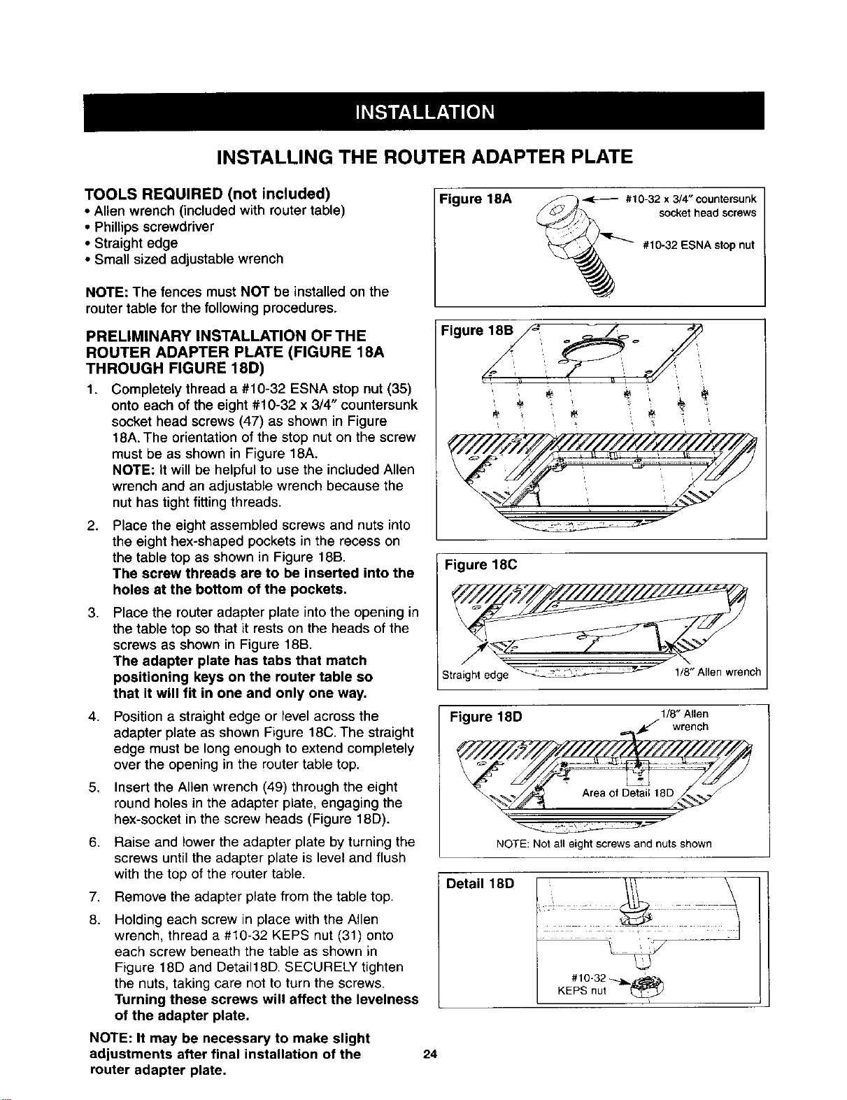
1. Completely thread a #10-32 ESNA stop nut (35)
onto each of the eight #10-32 x 3/4" countersunk
socket head screws (47) as shown in Figure
18A. The orientation of the stop nut on the screw
must be as shown in Figure 18A.
NOTE: it will be helpful to use the included Allen
wrench and an adjustable wrench because the
nut has tight fittingthreads.
2,
3.
4,
5.
6,
7,
8.
Place the eight assembled screws and nuts into
the eight hex-shaped pockets in the recess on
the table top as shown in Figure 18B.
The screw threads are to be inserted into the
holes at the bottom of the pockets.
Place the router adapter plate into the opening in
the table top so that it rests on the heads of the
screws as shown in Figure 18B.
The adapter plate has tabs that match
positioning keys on the router table so
that it will fit in one and only one way.
Position a straight edge or level across the
adapter plate as shown Figure 18C. The straight
edge must be long enough to extend completely
over the opening in the router table top.
Insert the Allen wrench (49) through the eight
round holes in the adapter plate, engaging the
hex-socket in the screw heads (Figure 18D).
Raise and lower the adapter plate by turning the
screws until the adapter plate is level and flush
with the top of the router table.
Remove the adapter plate from the table top.
Holding each screw in place with the Allen
wrench, thread a #10-32 KEPS nut (31) onto
each screw beneath the table as shown in
Figure 18D and Detai118D. SECURELY tighten
the nuts, taking care not to turn the screws.
Turning these screws will affect the levelness
of the adapter plate.
NOTE: It may be necessary to make slight
adjustments after final installation of the
router adapter plate.
Figure 18A _--_ _ #10-32 x 3/4" countersunk
_ socket head screws
'_''_ #10-32 ESNA stop nut
F,0",o,y
Figure 180
Straight edge" " _': _ _ " 1/8"Allen wrench
Figure 18D 1/8"Allen
NOTE: Not all eight screws and nuts shown
Detail 18D
#10-32 _,_ '
KEPS nut
24
Loading ...
Loading ...
Loading ...