Loading ...
Loading ...
Loading ...
4
3
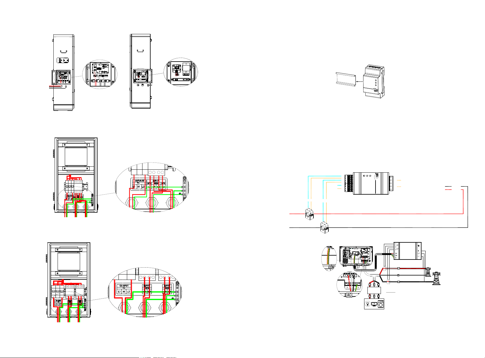
1.2.1 Installation and Wiring of Electric Meter SM-US-200
Fig 1.4 ARO Battery Wiring Diagram
Fig 1.5 ATS-5K Wiring Diagram
Fig 1.6 ATS-11.4K Wiring Diagram
a) Meter Mounting
Ø The meter should be mounted in a Power Distribution Box.
Ø Mount the meter on a 35mm DIN rail.
b) CT Installation
Install the two CTs with the Arrow pointing to the LOAD.
Ø Make sure the CT of L1 matched L1 input of the Service Panel that also match the L1 to
the inverter.
Ø Make sure the CT of L2 matched L2 input of the Service Panel that also match the L1 to
the inverter.
c) Meter Wiring
Ø When connecting the meter to the inverter, refer to the connection diagram below.
Fig 1.8
Fig 1.7
Fig 1.9
Ø RS485 cables Ground, B- & A+ was installed from the left to right when facing the
meter,Please refer to the silk screen on the meter.
4
L 1 CT
L 2 CT
3
2
1
4
3
2
1
B-
A+
RS485wires
Block1 Block2
1
2
3
4
5
wires from AC:
Green/Yellow(GND)-to pin 5
White(N)-to pin 3
Black(L2)-to pin 2
Red(L1)-to pin1
L1
L2
To the load
AC:CT wires
blue to pin 1,3
brown to pin 2,4
Loading ...
Loading ...
Loading ...