GR-UM-251-A-00
Download
Manual
Growatt New Energy
Growatt USA,Inc
9227 Reseda Blvd,#435 Northridge,CA 91324,USA.
1(866) 686-0298
www.growatt-america.com
T
E usaservice@ginverter.com
W
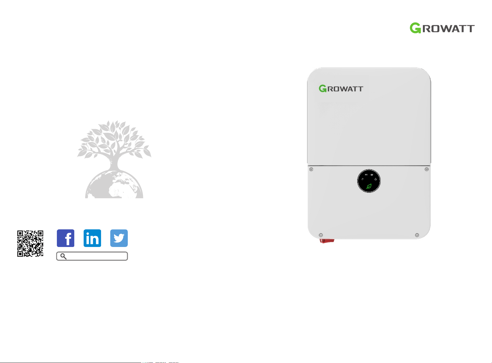
MIN 3K-11.4K TL-XH-US
&
Commissioning Guide

List
1.1 Energy Management System
Introduction
1.2 Check System Installation &
Power On
1 Power on the system
2 ShineTools APP Setup
2.1 APP Download
2.2 APP Introduction
2.3 Connecting to Local Wi-Fi
Network
3 Grid Code Mapping Table
4 Wi-Fi Network Configuration
5 Energy Management System
5.1 Management System Mode
Introduction
5.2 Energy Management System
setting
6 Battery Life Maintenance
7 Troubleshooting
Commissioning Error Code
8.1 Register an Account
8.2 Create a power plant
8.3 Add Data Logger to power plant
8 ShineServer Operation
9 Shinephone Introduction
9.1 APP Download
9.2 APP Introduction

1 Power on the system
1.1 Energy Management System Introduction
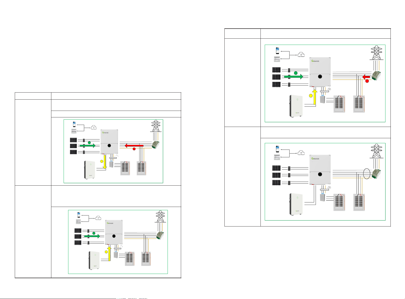
MIN 3K-11.4KTL-XH-US energy storage system diagram is shown in the figure below:
1
2
The system wiring diagram is as follows:
1.1.1 System Configuration Contains
1.2 Check System Installation & Power On
All components were installed according to the installation guides, please check the
following highlighted installation locations:
Energy Storage System / Off-Grid System.
Ø MIN 3-11.4KTL-XH-US inverter.
Ø ARO battery(s).
Ø ATS.
Ø Electric meter SM-US-200 .
Inverter Grid-Connected System.
Ø MIN 3-11.4K TL-XH-US inverter.
Ø Electric meter SM-US-200 (Optional ).
Product
Model
Function
Note
Inverter
MIN 3K-11.4KTL-XH-US
Energy
conversion
ARO Battery
ARO 6.6-9.9L-C1-US
Energy storage
UP TO 4
ATS
ATS 5K/11.4KT-US
EPS switching
Smart meter
SM-US-200
Energy
management
Button
RSD Button
Rapid shutdown
Accessory (included
in the package)
MIN 3- 11.4KTL XH-
US Inverter
Smart
Meter
US-200
Whole Home
Load
Backup
Load
Emergency
stop switch
Main Panel
Sub Panel
ATS
ARO Battery
Power Wire
Signal Wire
RS 485
MIN XH-US Inverter
L1 L2N
Back up
L1L2
ATS-US
L1 L2
L1
L2
N
L1 L2
EPS
BACKUP
L1
L2
N
Home Load
Backup Load
Power Grid
AC Grid
Output
Input
AC Panel
Sub AC Panel
Neutral bus-bar
Ground bar
GRID
EPS
BACKUP
SM-US-200
N
L2
N
L1
L1
+
+
-
-
CT
CT
Fig 1.1
Fig 1.2
Power on the system according to the MIN 3000-11400TL-XH-US Quick Guide which is
included in the inverter package/box.
Fig 1.3 Inverter Box Wiring Diagram
4
3
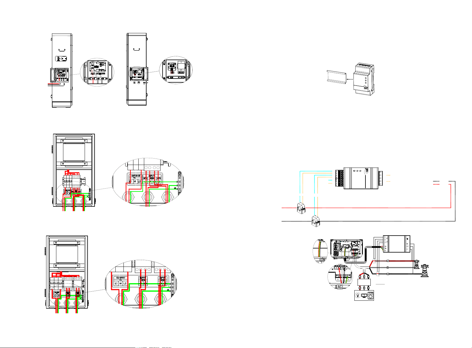
1.2.1 Installation and Wiring of Electric Meter SM-US-200
Fig 1.4 ARO Battery Wiring Diagram
Fig 1.5 ATS-5K Wiring Diagram
Fig 1.6 ATS-11.4K Wiring Diagram
a) Meter Mounting
Ø The meter should be mounted in a Power Distribution Box.
Ø Mount the meter on a 35mm DIN rail.
b) CT Installation
Install the two CTs with the Arrow pointing to the LOAD.
Ø Make sure the CT of L1 matched L1 input of the Service Panel that also match the L1 to
the inverter.
Ø Make sure the CT of L2 matched L2 input of the Service Panel that also match the L1 to
the inverter.
c) Meter Wiring
Ø When connecting the meter to the inverter, refer to the connection diagram below.
Fig 1.8
Fig 1.7
Fig 1.9
Ø RS485 cables Ground, B- & A+ was installed from the left to right when facing the
meter,Please refer to the silk screen on the meter.
4
L 1 CT
L 2 CT
3
2
1
4
3
2
1
B-
A+
RS485wires
Block1 Block2
1
2
3
4
5
wires from AC:
Green/Yellow(GND)-to pin 5
White(N)-to pin 3
Black(L2)-to pin 2
Red(L1)-to pin1
L1
L2
To the load
AC:CT wires
blue to pin 1,3
brown to pin 2,4
6
5
2 ShineTools APP Setup
2.1 APP Download
There are two ways to download the ShineTools APP:
a) Scan the QR code
Ø Scanning the QR code through phone camera for downloading the APP.
Fig2.1 ShineTools App QR code
b) APP Store
Ø Search for ShineTools App from app stores (App or Play Store).
Ø The ShineTools App icon is displayed the same as the Figure 4.
Ø Download and install the App by following the installation instructions.
Fig2.2 ShineTools App QR code
2.2 APP Introduction
ShineTools is used to connect the inverter with built-in WIFI at close range. We can view
the inverter system information and system fouction settings with it.
2.3 Connecting to Local Wi-Fi Network
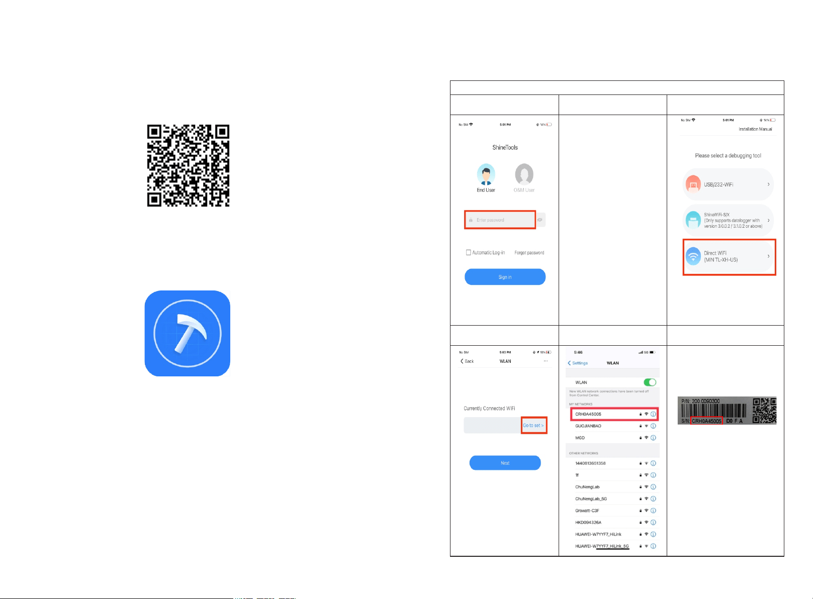
The steps for using APP are as follows:
Setup local Wi-Fi to communicate with the inverter
1.Login interface
2.Enter the default
password and log in
3.Tap in Direct WiFi
The default password is
oss+ day. Ex: if today's
date is Dec 29, 2020, the
default password would
be oss20201229, You can
change the password
according to the prompts
below.
4.Tap in Go to set
5. Open the Wi-Fi settings
on the mobile phone
6. The Wi-Fi name is the
Serial Number on the label
at the left side of the inverter.
The Wi-Fi password is
12345678
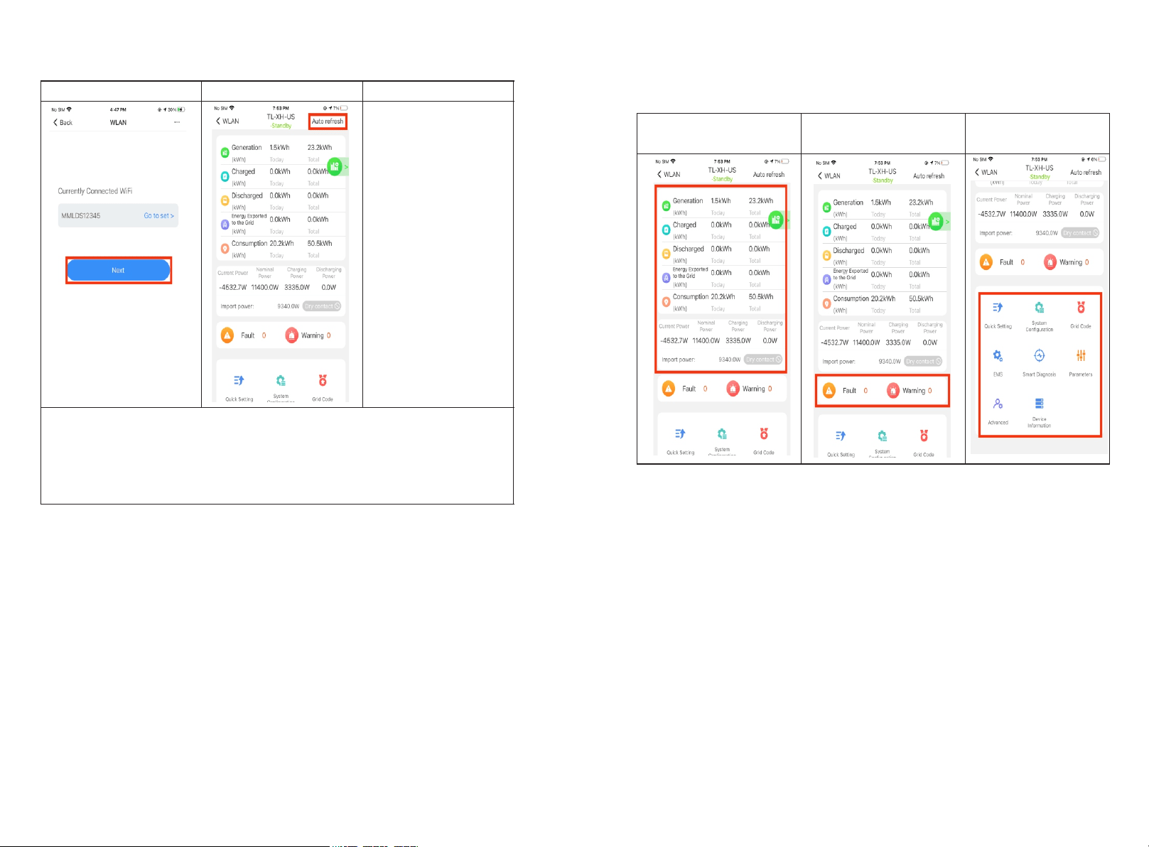
The main interface of local commissioning consists of three parts:
7. Tap in Next
8. Tap in Auto refresh
Now this APP has been
connected to the built-in
WIFI of the inverter.
Note:
When no data was present, the communication connection is unsuccessful and you will
need to reconnect the build-in WIFI of the inverter by turning off Wifi setting in the
phone and turn on again OR power cycle the system.
Also, keep the mobile phone within 3 meters of the inverter to ensure stable connection
between phone and inverter.
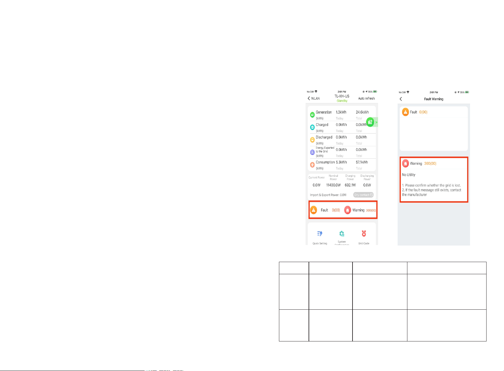
2.4 Local Commissioning Main Interface Introduction
Power generation
information
Fault warning message
Internal information
viewing and parameter
setting
8
7
The factory Default grid mode of the inverter is IEEE1547-240, which can adapt to the
most power grids. The different grid code can be changed according to local regulation
in the network configuration interface from Quick Setting in ShineTools App.
3 Grid Code Mapping Table
No.
Grid Code
Description
No.
Grid Code
Description
1
HECO-208
US Hawaii low-
voltage power grid
2
HECO-240
US Hawaii low-
voltage power grid
3
IEEE1547-208
US low-voltage
power grid
4
IEEE1547-240
US low-voltage
power grid
5
PRC-East-208
Eastern US low-
voltage power grid
6
PRC-East-240
Eastern US low-
voltage power grid
7
PRC-Quebec-
208
Canada Quebec
low-voltage power
grid
8
PRC-Quebec-
240
Canada Quebec
low-voltage power
grid
9
RULE21-208
US California low-
voltage power grid
10
RULE21-240
US California low-
voltage power grid
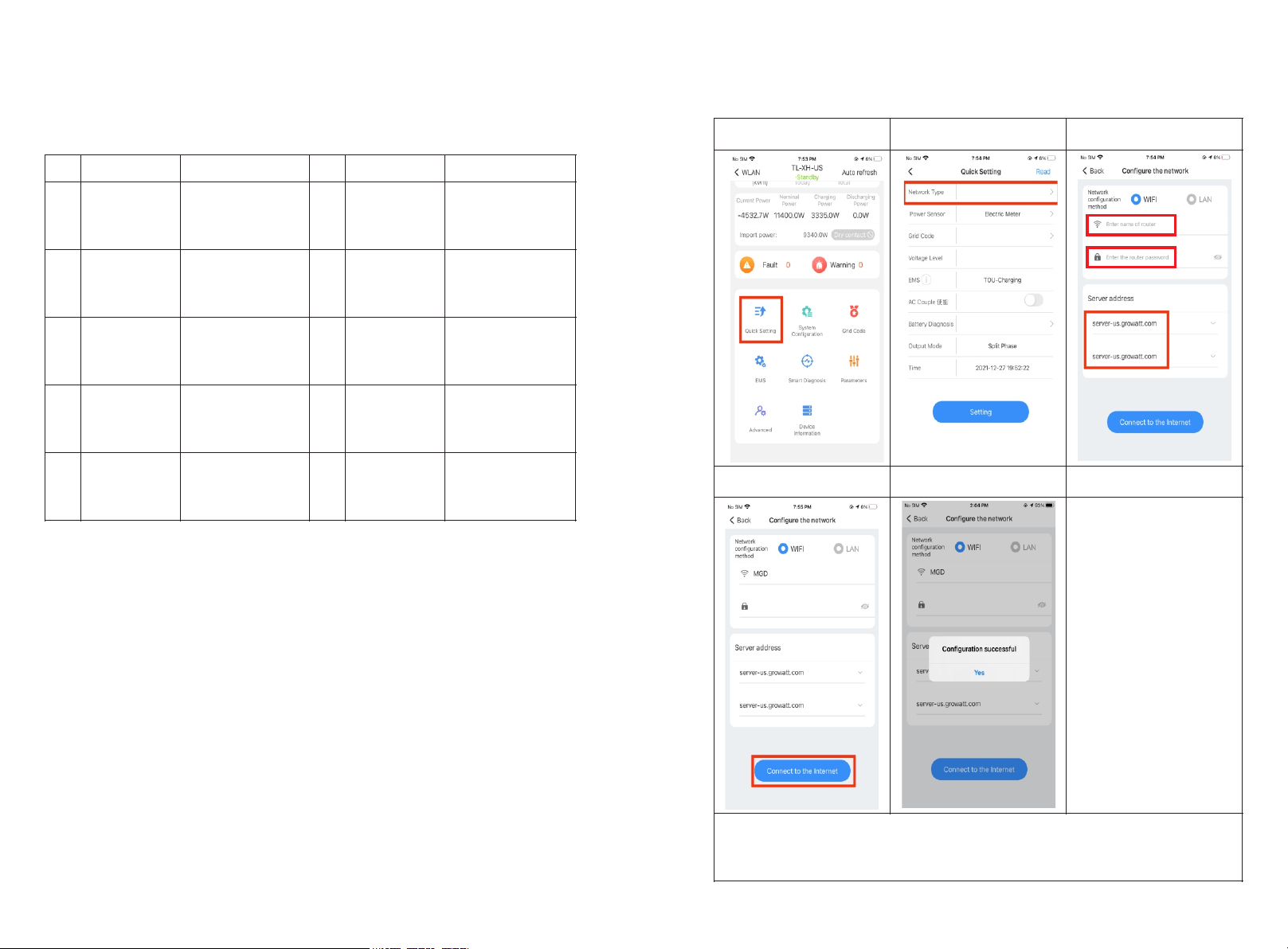
Wi-Fi Network Configuration 4
First time install the inverter, the inverter needs to be configured to connect to the home
Wi-Fi to ensure the remote monitoring.
1.Tap in Quick Setting icon
2.Choose Network
configuration
3.Enter network
information
4.Tap in Connect to the
internet icon
5.Prompt message for
successful configuration
Note:
If the network configuration has failed, please carefully check the Wi-Fi name,
password and antenna installation connection, and then try again.
Notice: The inverter does not support 5GHz WiFi network.
10
9
5 Energy Management System
Notice: First time install the energy storage system, charge the battery for at least 1 hours
or up to 60% SOC before powering off the system. This action will keep up the battery
power to avoid running out while waiting for PTO.
There are two ways to charge the battery.
Ø The first is to connect the PV array to the PV of the inverter and turn off the AC output
breaker of the inverter.
Ø The second method is to connect the AC output of the inverter to the grid without any
PV input, set the EMS mode of the system to TOU Battery Charging (5.2.3), and turn
on the AC charging function (5.2.2).
5.1 Management System Mode Introduction
The MIN 3K-11.4K TL-XH-US system provides four energy storage modes to choose from. .
Storage Mode
Description
TOU Battery
Charging
Charge battery from PV production and grid power (if needed) until
it is full. Only then use PV production for self-consumption and grid
export
TOU Battery
Discharging
If PV Production < Inverter Maximum Production (nameplate or
limited power), discharge battery for self-consumption and grid
export until the inverter reaches its power limit or max battery
discharge power.
Maximum self-
consumption
Use PV production for self-consumption, then charge/discharge
battery as needed to maximize self-consumption
Maximum self-
consumption
Export Limit
The power output from the system to the grid is limited at the set
value
5.2 Energy Management System setting
For the photovoltaic energy storage system, several functions of the system need to set
after the first installation and power-up.
11
Shine Phone
Shine Server
PV Panel
PV Panel
PV Panel
Cloud Server
Inverter
HV Battery
Grid
Power Meter
Backup load Panel Home load Panel
PV1+
Bus+
Bus-
Bat+
Bat-
L1
L2
N
PE
L1 L2
L1
L2
N
RS485
PV1-
PV2+
PV2-
PV3+
PV3-
L2 N PEL1
PE
1
2
3
Shine Phone
Shine Server
PV Panel
PV Panel
PV Panel
Cloud Server
Inverter
HV Battery
Grid
Power Meter
Backup load Panel Home load Panel
PV1+
Bus+
Bus-
Bat+
Bat-
L1
L2
N
PE
L1 L2
L1
L2
N
RS485
PV1-
PV2+
PV2-
PV3+
PV3-
L2 N PEL1
PE
1
2
Shine Phone
Shine Server
PV Panel
PV Panel
PV Panel
Cloud Server
Inverter
HV Battery
Grid
Power Meter
Backup load Panel Home load Panel
PV1+
Bus+
Bus-
Bat+
Bat-
L1
L2
N
PE
L1 L2
L1
L2
N
RS485
PV1-
PV2+
PV2-
PV3+
PV3-
L2 N PEL1
PE
1
3
2
Shine Phone
Shine Server
PV Panel
PV Panel
PV Panel
Cloud Server
Inverter
HV Battery
Grid
Power Meter
Backup load Panel Home load Panel
PV1+
Bus+
Bus-
Bat+
Bat-
L1
L2
N
PE
L1 L2
L1
L2
N
RS485
PV1-
PV2+
PV2-
PV3+
PV3-
L2 N PEL1
PE
Export Limit
1.Tap in Quick Setting icon
2.Choose Network
configuration
3.Enter network
information
4.Tap in setting
5.Prompt message for
successful setting
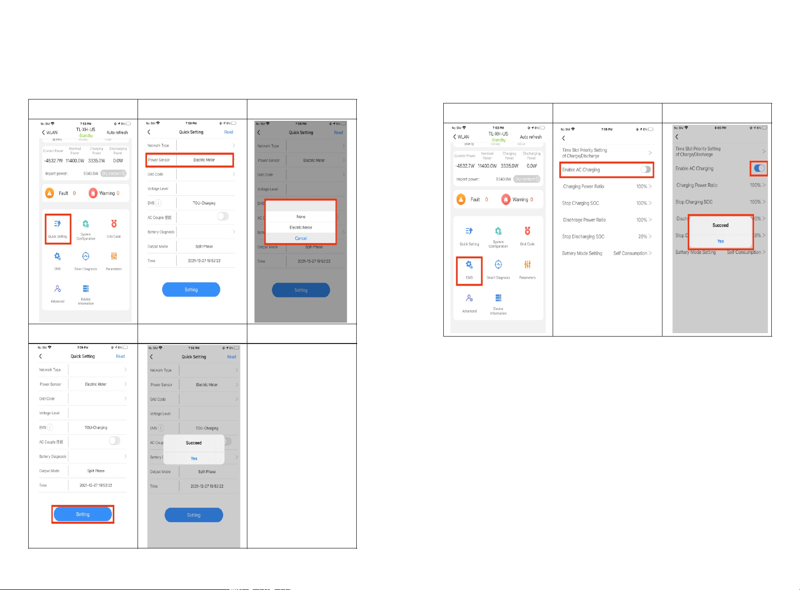
5.2.2 AC Charging Setting
The AC charging is used to set whether to allow charging the battery from the Grid.
Factory Default is Disabled.
1.Tap in Charge and
Discharge Management
2.Find Enable AC Charging
3.Tap in ON/OFF button.
1413
5.2.1 Power Sensor Setting
If an electric meter is installed in the system, please set. Factory Default is Disabled.
Note: Power Sensor: iOS = Electric meter
Android = Meter
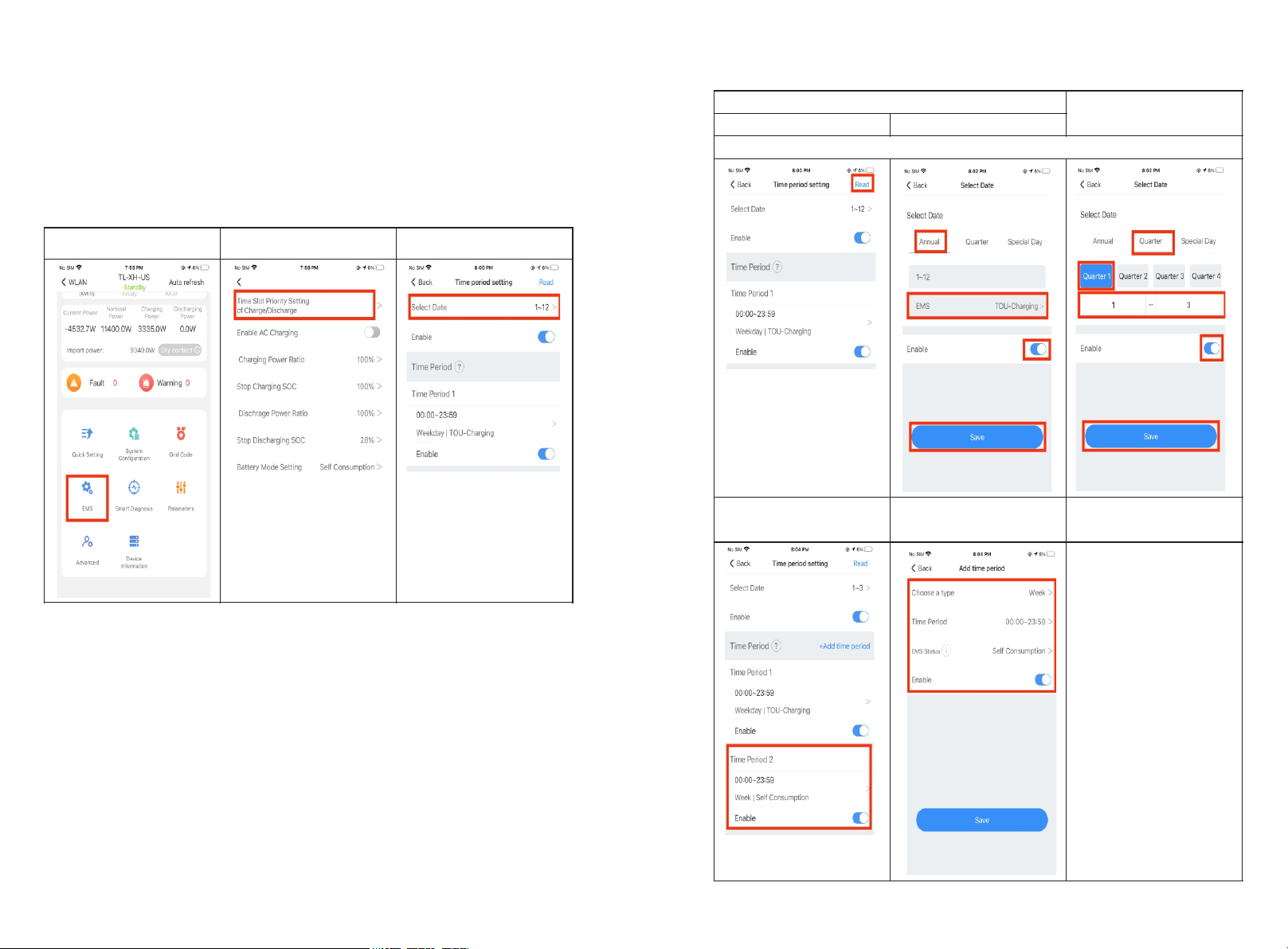
1.Tap in EMS
2.Tap in Time Slot…
3.Create the date and time
period.
For Backup ONLY scenarios ,it's done on No. 5
4.Select the Quarter to be
set, Four quarters can be
set
4.Select the TIME to be set
5.Select the YEAR to be set
You only need to select the season or year to set.
5.Increase time period,
Maximum support 9 time
periods
6.Set the mode within the
time period
7. If you need to set more
quarter or time periods, you
need
to operate step 4, 5, 6
multiple times You can also
set the energy storage
mode for special days if
necessary.
1616
5.2.3 EMS Mode Setting:
If an ARO battery is installed in the system, you need to set the energy storage mode.
Factory Default is Maximum Self-Consumption.
Example: If the energy storage system is to be used as backup and only use the battery
when the grid is powered off, set the battery charging and discharging time period to 24
hours for TOU Battery Charging.
15
6 Battery Life Maintenance
(Important)
a) TUnplug Battery power, Battery Communication cables and turn OFF battery modules
power (Check battery quick installation guide for the detail) .
if the following conditions were met:
Ø The installation is not completed.
Ø No PV and AC power can charge the battery.
b) Charge the battery SOC above 60% or higher after installation is complete and
pending for AHJ/city review and approval.
Commissioning Error Code 7
Troubleshooting
Enter the local commissioning home page, and view the fault and alarm information on
the main interface if there are exist after installation. The fault and alarm code on the
ShineServer Page will be the same in the APP.
If you find a fault or alarm, please click it, and then you will be redirected to the interface
of fault explanation and handling tips.
1. Common Fault and warning Codes
Fault code
Fault name
Possible cause
suggestion
Error 200
AFCI Fault
There is a problem on
the wiring connection
1.After shutdown, check the
panel terminal.
2.Decrease AFCI sensitivity
and restart.
3.If error message still exists,
contact manufacturer.
Error 201
Residual current
High
PV panel insulation
problem
1.Restart inverter. (Related
to Grounding fault?)
2.If error message still exists,
contact manufacturer.
1817
Error 202
PV Voltage High
Too many PV panels
connected in series
1.Immediately disconnect the
DC switch and check the PV
voltage.
2.If the fault code still exists
after the normal voltage is
restored, contact manufacturer.
Error 203
PV Isolation Low
PV panel insulation
problem
1. Check PV panel and wiring.
Error 204
PV Reversed
PV positive and
negative are
reversed
1.After shutdown, Check the
inverter terminal.
2. Restart inverter.
3.If error message still exists,
contact manufacturer.
Error 300
AC overvoltage
Grid voltage
overvoltage
1.Check grid voltage.
2. If the error message still exists
despite the grid voltage being
within the spec range, contact
manufacturer.
Error 301
AC reversed
AC wiring error
1.Check AC terminals.
2.If error message still exists,
contact manufacturer.
Error 302
No AC
Connection
No AC Connection
1.After shutdown, Check AC
wiring.
2. If error message still exists,
contact manufacturer.
Error 303
NE abnormal
N or PE wring error
1.Check PE wiring.
2.Check N wiring.
Error 304
AC F Outrange
Abnormal grid
frequency
1. Restart inverter.
2. If error message still exists,
contact manufacturer.
Warning
217
BDC Abnormal
ARO battery error
1.Check ARO battery terminals
2.Check the connection.
between the inverter and the
ARO battery.
Warning
218
BDC Bus
Disconnect
Inverter and BDC
wiring failure
1. Check the wire connection
between the inverter and the
ARO battery.
2.If error message still exists,
contact manufacturer.
ShineServer Operation 8
ShineServer is the online monitoring platform that allows remote access through the
ShinePhone App or any web browser. However, the premise is that the Wi-Fi network has
been configured.
Account and plant information will be the same in both the web browser version and on
the ShinePhone App.
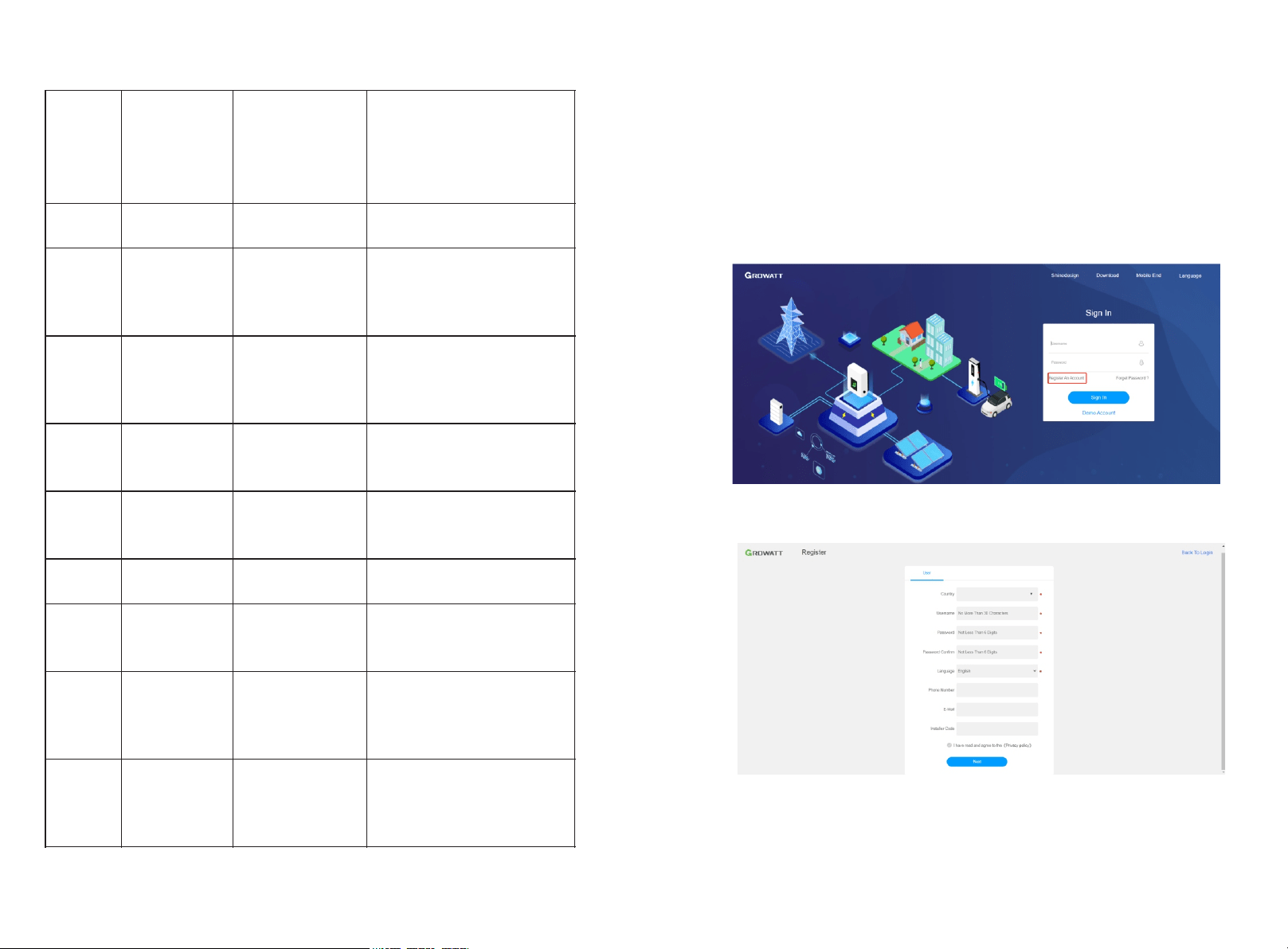
8.1 Register an Account
a) Log in to our monitoring website http://server-us.growatt.com and click Register an
Account.
b) Fill in the appropriate information on the registration interface and log into the
account after the registration is completed.
8.2 Create a power plant
a) When you log into your account for the first time, you will be prompted to register a
power plant.
b) Click Add Plant on the upper right hand corner to create a power plant. A single
account can contain multiple power plants.
2019
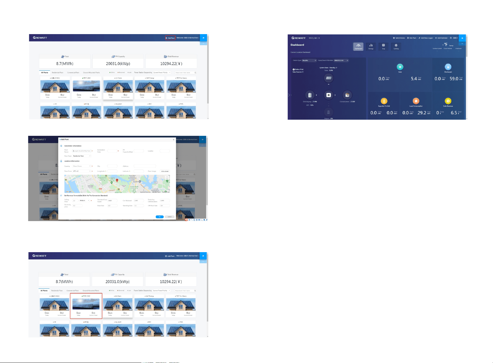
c) Fill in the appropriate power plant information in order to complete the power plant
creation.
8.3 Add Data Logger to power plant
a) Click on the power plant just created, enter the power plant page, and then add a
data logger.The SN number of the collector is on the barcode on the side of the
inverter, starting with VC. A power plant can contain multiple data loggers.
b) When you have completed these steps, you will be able to view the inverter system
remotely through the ShinePhone APP and through any browser.
2221
9 Shinephone Introduction
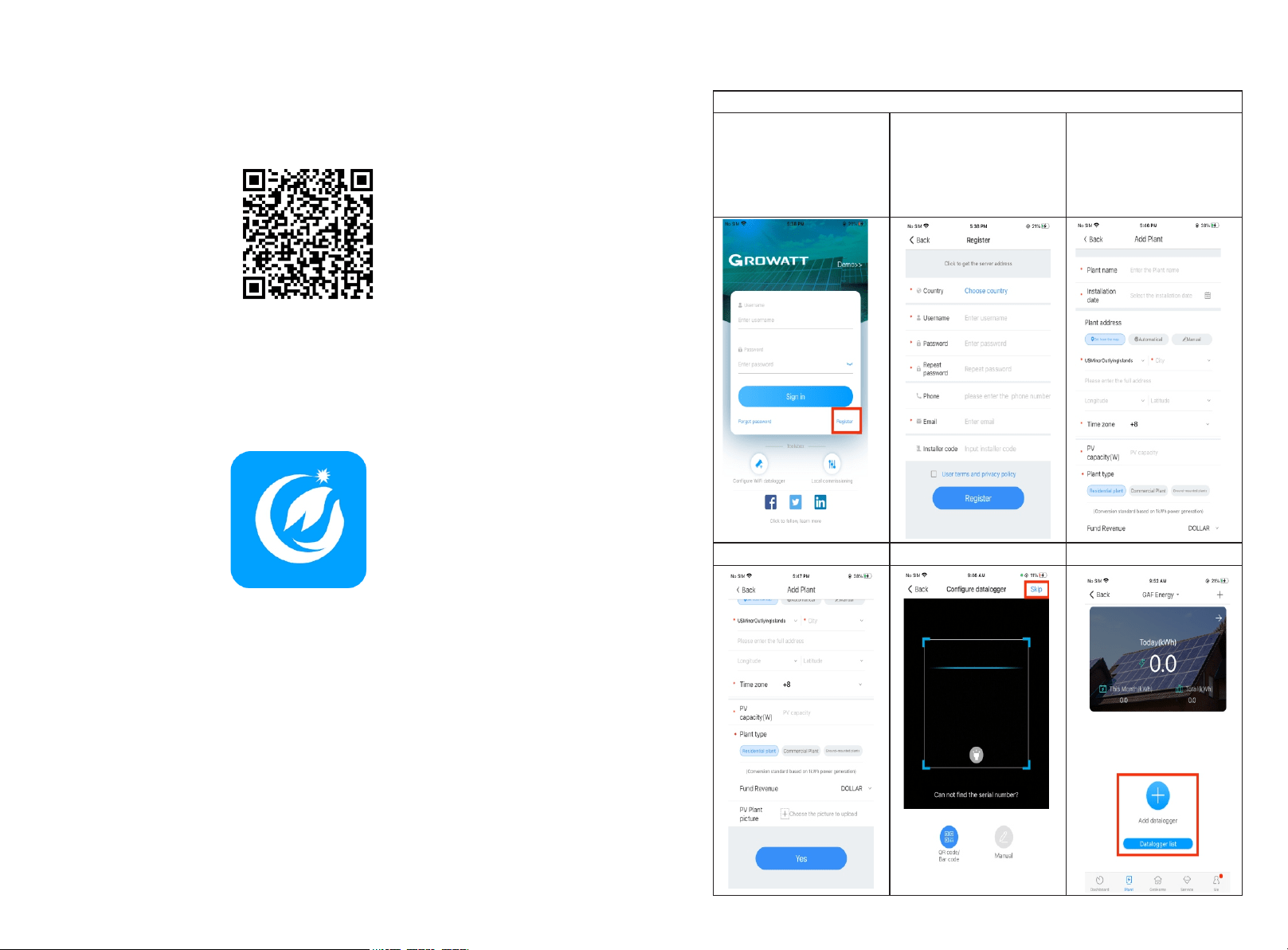
9.1 APP Download
There are two ways to download the ShinePhone APP:
c) Scan the QR code
Fig 9.1 ShinePhone downloading QR code
Scanning the QR code through WeChat or IOS's Camera, then download the APP.
d) APP Store
Search for ShinePhone from app stores, download the installation package, and install
the ShinePhone app by following the instructions.the ShinePhone icon is displayed on
the home screen.
Fig 9.2 Icon of APP
9.2 APP Introduction
Shinephone can remotely monitor the inverter system information, which has the same
function as shineserver, and the two information are shared. We can also register and
create power stations through the shinephone app.
Setup local Wi-Fi to communicate with the inverter
1.Tap in Register
2. Fill the register info,
Notice: For Installer code:
ask for your installer, once
you fill your installer code,
your PV system would be
authorized and monitored
by your installer.
3.Fill the plant info
4.Continue fill the plant
5.Tap in skip
6. Add collector
24
23
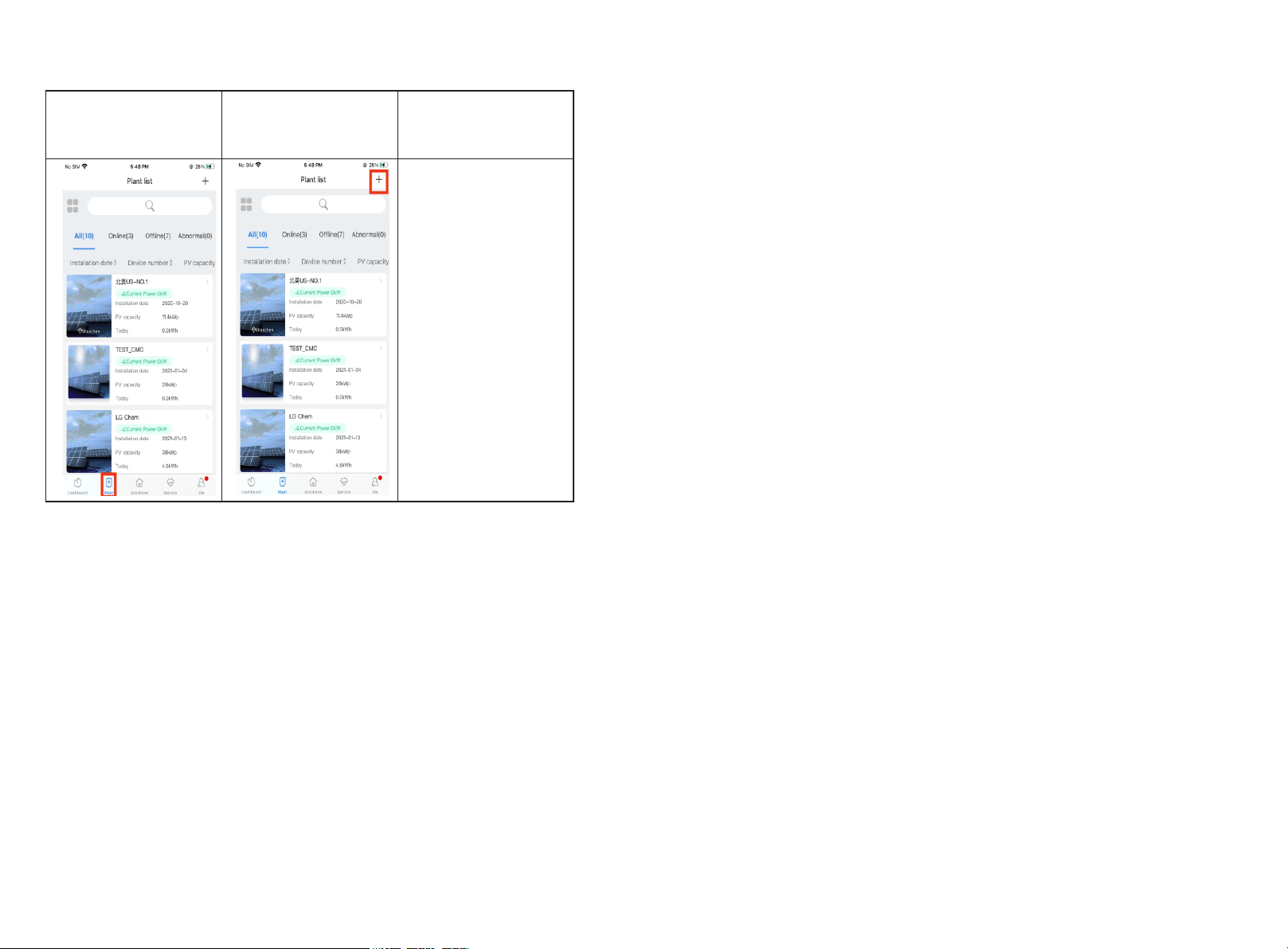
7. The Plant page display
the list of plants under the
plant account
8.tap in “+” to add the
Plant.
25
Growatt USA,Inc
9227 Reseda Blvd,#435 Northridge,CA 91324,USA.
1(866) 686-0298
www.growatt-america.com
T
E usaservice@ginverter.com
W
