OWNERS GUIDE
MARVEL PROFESSIONAL UNDERCOUNTER REFRIGERATION
THE ORIGINAL REFRIGERATION EXPERTS SINCE 1892
FOR MODEL # MPBV415
OWNER'S GUIDE
MARVEL PROFESSIONAL UNDERCOUNTER REFRIGERATION
THE ORIGINAL REFRIGERATION EXPERTS SINCE 1892
FOR MODEL # MPRE424
Welcome to the Marvel Experience
Thank you for choosing our quality American-built product
to add to your home. We are thrilled to welcome you to
our growing community of Marvel owners, who trust in our
products and our support.
The information in this guide is intended to help you install
and maintain your new Marvel undercounter model to
protect and prolong its lifetime. We encourage you to
contact our Technical Support team at (616) 754-5601 with
any questions.
Got a Marvelous Design?
We would love to see how your Marvel product looks in its
new home. Send us photos at marketing@marvelrefrigera-
tion.com, and we might feature your Marvel home design
on our website and social media!
Bonus Third-Year Warranty Free with Product
Registration
Your Marvel Professional product
qualies for a one-year extension
of the two-year warranty coverage
from your date of purchase, free of
charge. To take advantage of this
third-year warranty, be sure to reg-
ister your product with Marvel within
60 days from the date of purchase at
marvelrefrigeration.com and provide
proof of purchase.
Thank you again for investing in Marvel for your home!
WELCOME
XXXXXXXXXXXX
XXXXXXXXXXXX
MARVEL
g
R600A
It is important you send in your warranty registration card
immediately after taking delivery of your appliance or you
can register online at www.marvelrefrigeration.com.
The following information will
be required when registering
your appliance:
Service Number
Serial Number
Date of Purchase
Dealer’s name and address
The service number and serial number can be found on the
serial plate which is located inside the cabinet on the left
side near the top.
Warranty Registration
Online registra-
tion available at
www.marvelrefrig-
eration.com

TABLE OF CONTENTS
Tip: Click on any section below to jump directly there
Safety
Important Safety Instructions
Installation
Unpacking Your Appliance
Electrical
Cutout & Product Dimensions
Installing Your Appliance
Side-by-Side & Stacking Installations
Installing the anti-tip device
Door Reversal
Maintenance
Care and Cleaning
Stainless Steel Maintenance
Extended Non-Use
Operating Instructions
Using Your Electronic Control
Interior Adjustments
Energy Savng Tips
Service
Obtaining Service
Wire Diagram
Product Liability
Warranty Claims
Parts List
Ordering Replacement Parts
R600a Specifications
System Diagnosis Guide
Compressor Specifications
Troubleshooting Extended
Control Operation - Service
Service Mode
Thermistor
Defrost
Remove Fan and Cover
Warranty
3
NOTE
!
CAUTION
Important Safety Instructions
Warnings and safety instructions appearing in this guide
are not meant to cover all possible conditions and situa-
tions that may occur. Common sense, caution, and care
must be exercised when installing, maintaining, or operat-
ing this appliance.
Recognize Safety Symbols,
Words, and Labels.
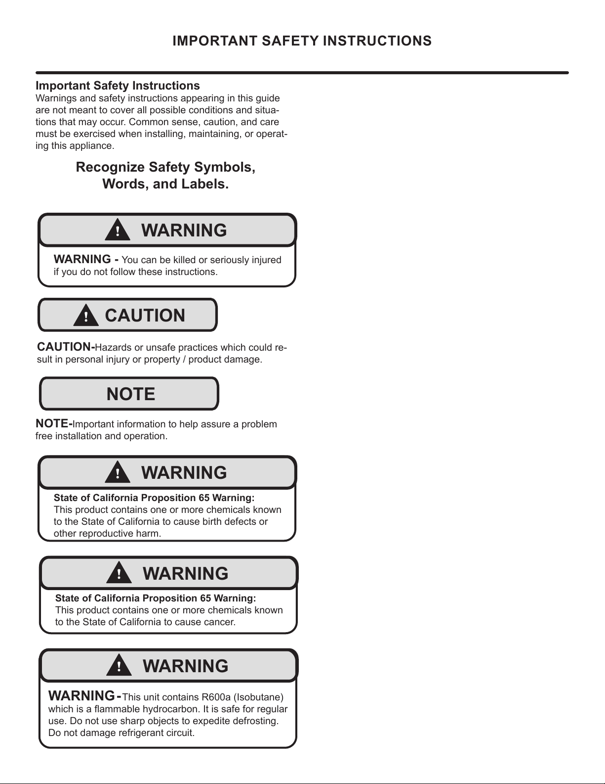
CAUTION-Hazards or unsafe practices which could re-
sult in personal injury or property / product damage.
NOTE-Important information to help assure a problem
free installation and operation.
IMPORTANT SAFETY INSTRUCTIONS
!
WARNING
WARNING - You can be killed or seriously injured
if you do not follow these instructions.
!
WARNING
State of California Proposition 65 Warning:
This product contains one or more chemicals known
to the State of California to cause cancer.
!
WARNING
State of California Proposition 65 Warning:
This product contains one or more chemicals known
to the State of California to cause birth defects or
other reproductive harm.
!
WARNING
WARNING - This unit contains R600a (Isobutane)
which is a ammable hydrocarbon. It is safe for regular
use. Do not use sharp objects to expedite defrosting.
Do not damage refrigerant circuit.
4
NOTE
!
WARNING
WARNING - Dispose of the plastic bags which can
be a suocation hazard.
UNPACKING YOUR APPLIANCE
!
CAUTION
!
WARNING
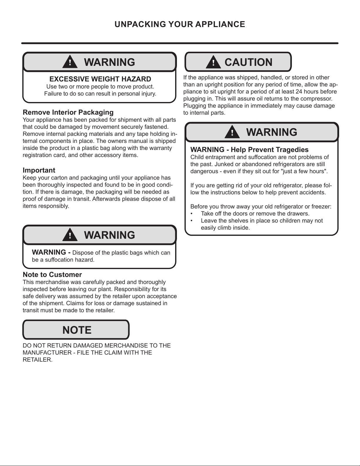
WARNING - Help Prevent Tragedies
Child entrapment and suocation are not problems of
the past. Junked or abandoned refrigerators are still
dangerous - even if they sit out for "just a few hours".
If you are getting rid of your old refrigerator, please fol-
low the instructions below to help prevent accidents.
Before you throw away your old refrigerator or freezer:
• Take o the doors or remove the drawers.
• Leave the shelves in place so children may not
easily climb inside.
!
WARNING
EXCESSIVE WEIGHT HAZARD
Use two or more people to move product.
Failure to do so can result in personal injury.
Remove Interior Packaging
Your appliance has been packed for shipment with all parts
that could be damaged by movement securely fastened.
Remove internal packing materials and any tape holding in-
ternal components in place. The owners manual is shipped
inside the product in a plastic bag along with the warranty
registration card, and other accessory items.
Important
Keep your carton and packaging until your appliance has
been thoroughly inspected and found to be in good condi-
tion. If there is damage, the packaging will be needed as
proof of damage in transit. Afterwards please dispose of all
items responsibly.
Note to Customer
This merchandise was carefully packed and thoroughly
inspected before leaving our plant. Responsibility for its
safe delivery was assumed by the retailer upon acceptance
of the shipment. Claims for loss or damage sustained in
transit must be made to the retailer.
DO NOT RETURN DAMAGED MERCHANDISE TO THE
MANUFACTURER - FILE THE CLAIM WITH THE
RETAILER.
If the appliance was shipped, handled, or stored in other
than an upright position for any period of time, allow the ap-
pliance to sit upright for a period of at least 24 hours before
plugging in. This will assure oil returns to the compressor.
Plugging the appliance in immediately may cause damage
to internal parts.
5

Electrical Connection
A grounded 115 volt, 15 amp dedicated circuit is required.
This product is factory equipped with a power supply
cord that has a three-pronged, grounded plug. It must be
plugged into a mating grounding type receptacle in ac-
cordance with the National Electrical Code and applicable
local codes and ordinances (see gure below). If the circuit
does not have a grounding type receptacle, it is the respon-
sibility and obligation of the customer to provide the proper
power supply. The third ground prong should not, under
any circumstances, be cut or removed.
NOTE
Ground Fault Circuit Interrupters (GFCI) are prone to nui-
sance tripping which will cause the appliance to shut down.
GFCI’s are generally not used on circuits with power equip-
ment that must run unattended for long periods of time, un-
less required to meet local building codes and ordinances.
ELECTRICAL
Do not remove
ground prong
Electrical Shock Hazard
• Do not use an extension cord with this appliance.
They can be hazardous and can degrade product
performance.
• This appliance should not, under any circumstanc-
es, be installed to an ungrounded electrical supply.
• Do not remove the grounding prong from the power
cord.
• Do not use an adapter.
• Do not splash or spray water from a hose on the
appliance. Doing so may cause an electrical shock,
which may result in severe injury or death.
!
WARNING
6
"C"
CUTOUT AND PRODUCT DIMENSIONS
"A"
"B"
"D"
"E"
Solid door
shown
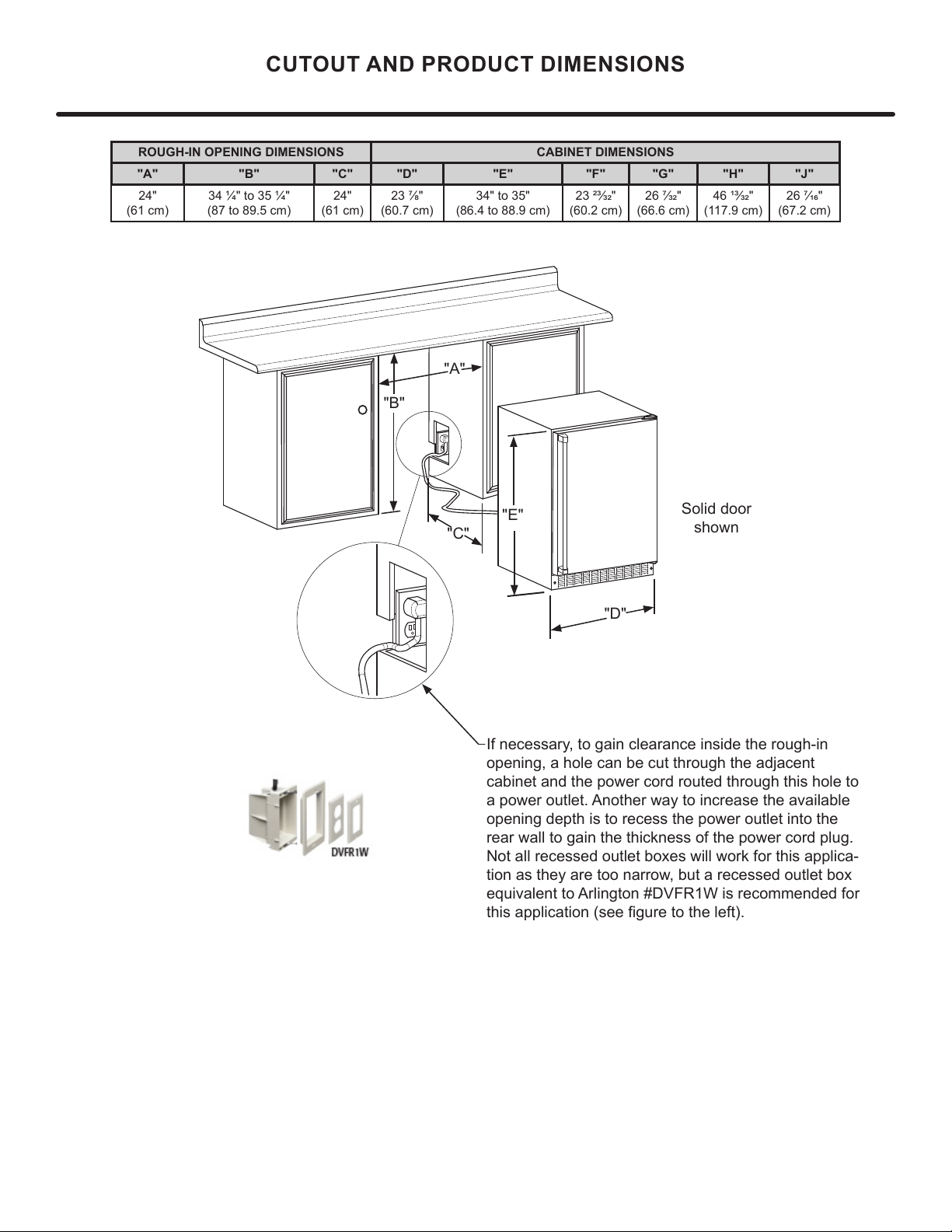
If necessary, to gain clearance inside the rough-in
opening, a hole can be cut through the adjacent
cabinet and the power cord routed through this hole to
a power outlet. Another way to increase the available
opening depth is to recess the power outlet into the
rear wall to gain the thickness of the power cord plug.
Not all recessed outlet boxes will work for this applica-
tion as they are too narrow, but a recessed outlet box
equivalent to Arlington #DVFR1W is recommended for
ROUGH-IN OPENING DIMENSIONS CABINET DIMENSIONS
"A" "B" "C" "D" "E" "F" "G" "H" "J"
24"
24"
7
"D"
"E"
"F"
"G"
"H"
"J"
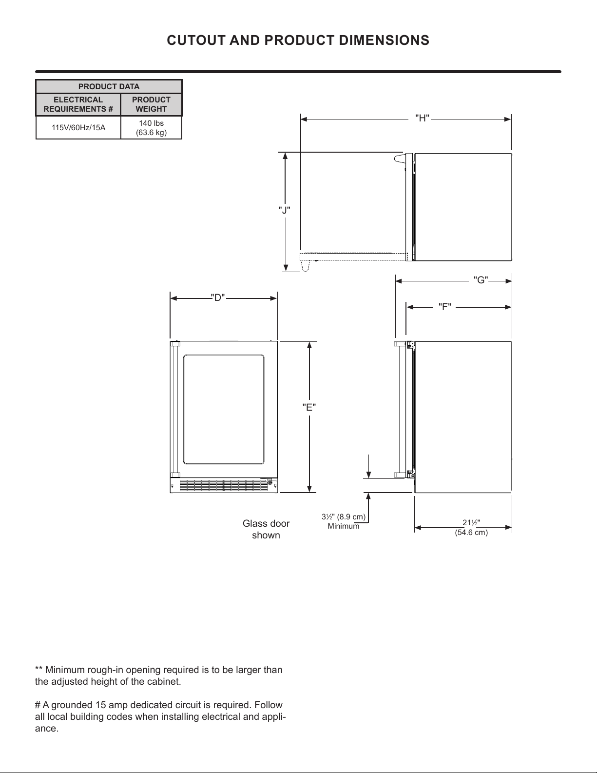
CUTOUT AND PRODUCT DIMENSIONS
PRODUCT DATA
ELECTRICAL
REQUIREMENTS #
PRODUCT
WEIGHT
140 lbs
** Minimum rough-in opening required is to be larger than
the adjusted height of the cabinet.
all local building codes when installing electrical and appli-
ance.
3
1
2
Minimum
Glass door
shown
21
1
2"
8
!
CAUTION
Front grille
screws
Select Location
The proper location will ensure peak performance of your
appliance. We recommend a location where the unit will
be out of direct sunlight and away from heat sources. To
ensure your product performs to specications, the recom-
mended installation location temperature range is from 55
to 100°F (13 to 38°C).
Cabinet Clearance
Ventilation is required from the bottom front of the appli-
ance. Keep this area open and clear of any obstructions.
Adjacent cabinets and counter top can be installed around
the appliance as long as the front grille remains unobstruct-
ed. All Marvel Professional models with articulated hinges
are intended for built-in applications only.
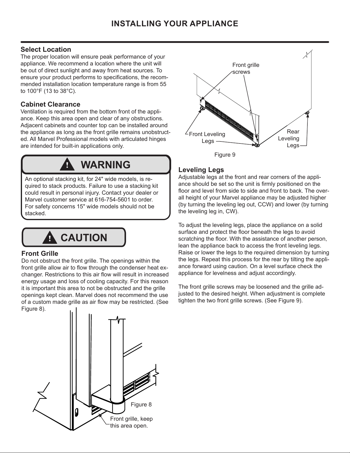
Front Grille
Do not obstruct the front grille. The openings within the
front grille allow air to ow through the condenser heat ex-
changer. Restrictions to this air ow will result in increased
energy usage and loss of cooling capacity. For this reason
it is important this area to not be obstructed and the grille
openings kept clean. Marvel does not recommend the use
of a custom made grille as air ow may be restricted. (See
Figure 8).
INSTALLING YOUR APPLIANCE
!
WARNING
An optional stacking kit, for 24" wide models, is re-
quired to stack products. Failure to use a stacking kit
could result in personal injury. Contact your dealer or
Marvel customer service at 616-754-5601 to order.
For safety concerns 15" wide models should not be
stacked.
Figure 9
Front Leveling
Legs
Leveling Legs
Adjustable legs at the front and rear corners of the appli-
ance should be set so the unit is rmly positioned on the
oor and level from side to side and front to back. The over-
all height of your Marvel appliance may be adjusted higher
(by turning the leveling leg out, CCW) and lower (by turning
the leveling leg in, CW).
To adjust the leveling legs, place the appliance on a solid
surface and protect the oor beneath the legs to avoid
scratching the oor. With the assistance of another person,
lean the appliance back to access the front leveling legs.
Raise or lower the legs to the required dimension by turning
the legs. Repeat this process for the rear by tilting the appli-
ance forward using caution. On a level surface check the
appliance for levelness and adjust accordingly.
The front grille screws may be loosened and the grille ad-
justed to the desired height. When adjustment is complete
tighten the two front grille screws. (See Figure 9).
Rear
Leveling
Legs
Figure 8
Front grille, keep
this area open.
9
SIDE-BY-SIDE AND STACKING INSTALLATIONS
Side-by-Side Installation
Other Site Requirements
Units must operate from separate, properly grounded elec-
trical receptacles placed according to each unit's electrical
specications requirements.
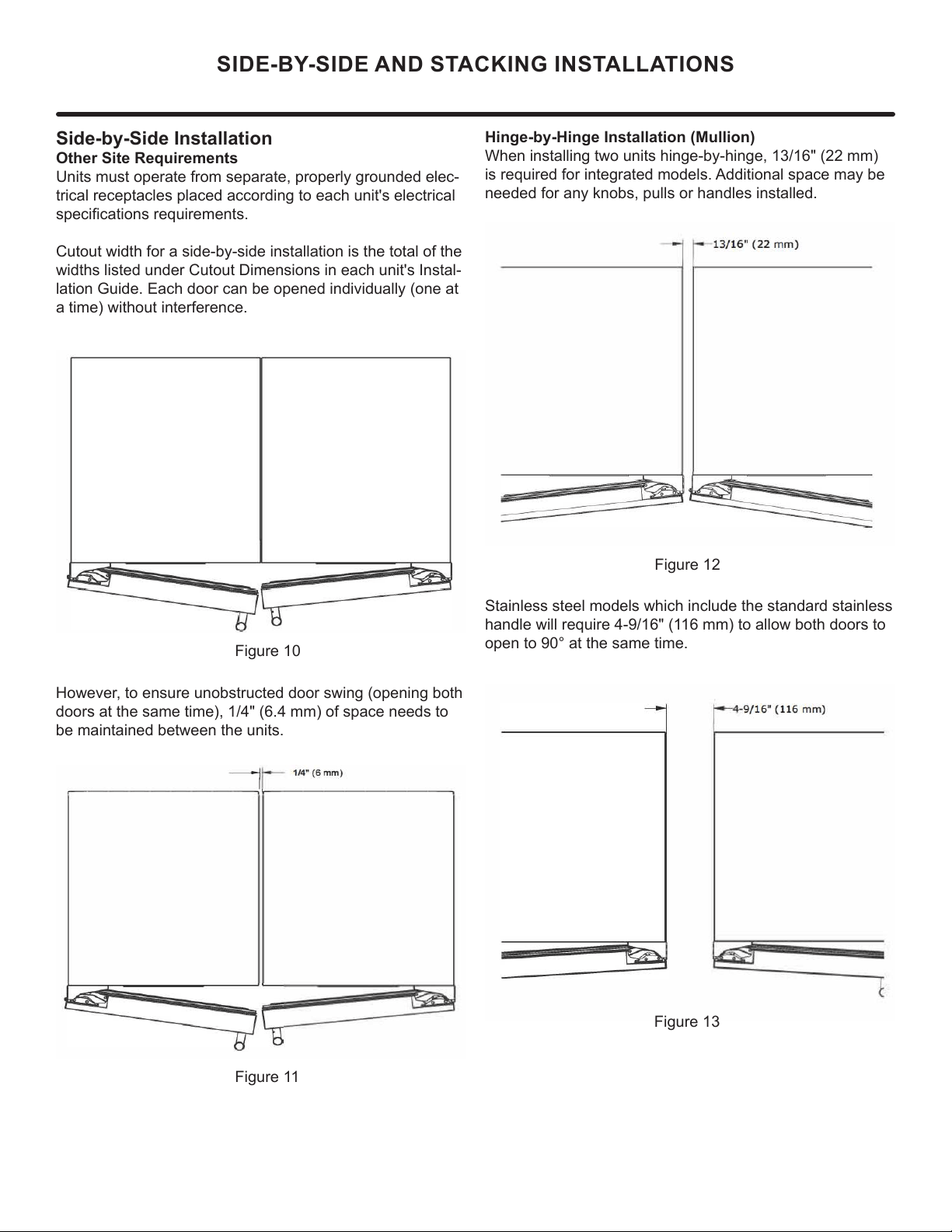
Cutout width for a side-by-side installation is the total of the
widths listed under Cutout Dimensions in each unit's Instal-
lation Guide. Each door can be opened individually (one at
a time) without interference.
Figure 10
However, to ensure unobstructed door swing (opening both
doors at the same time), 1/4" (6.4 mm) of space needs to
be maintained between the units.
Hinge-by-Hinge Installation (Mullion)
When installing two units hinge-by-hinge, 13/16" (22 mm)
is required for integrated models. Additional space may be
needed for any knobs, pulls or handles installed.
Stainless steel models which include the standard stainless
handle will require 4-9/16" (116 mm) to allow both doors to
open to 90° at the same time.
Figure 11
Figure 12
Figure 13
10
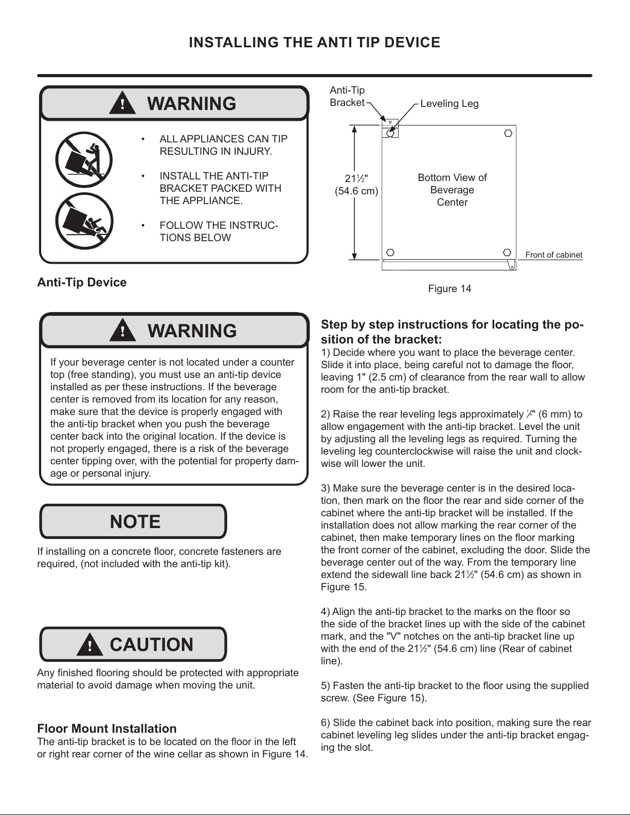
INSTALLING THE ANTI TIP DEVICE
Step by step instructions for locating the po-
sition of the bracket:
1) Decide where you want to place the beverage center.
leaving 1" (2.5 cm) of clearance from the rear wall to allow
room for the anti-tip bracket.
¹
" (6 mm) to
allow engagement with the anti-tip bracket. Level the unit
by adjusting all the leveling legs as required. Turning the
leveling leg counterclockwise will raise the unit and clock-
wise will lower the unit.
3) Make sure the beverage center is in the desired loca-
cabinet where the anti-tip bracket will be installed. If the
installation does not allow marking the rear corner of the
beverage center out of the way. From the temporary line
1
2" (54.6 cm) as shown in
Figure 15.
the side of the bracket lines up with the side of the cabinet
mark, and the "V" notches on the anti-tip bracket line up
with the end of the 21
1
2" (54.6 cm) line (Rear of cabinet
line).
screw. (See Figure 15).
6) Slide the cabinet back into position, making sure the rear
cabinet leveling leg slides under the anti-tip bracket engag-
ing the slot.
Front of cabinet
Figure 14
21
1
2"
(54.6 cm)
Anti-Tip
Bracket
Leveling Leg
Bottom View of
Beverage
Center
Floor Mount Installation
or right rear corner of the wine cellar as shown in Figure 14.
!
WARNING
• ALL APPLIANCES CAN TIP
RESULTING IN INJURY.
• INSTALL THE ANTI-TIP
BRACKET PACKED WITH
THE APPLIANCE.
• FOLLOW THE INSTRUC-
TIONS BELOW
!
CAUTION
NOTE
material to avoid damage when moving the unit.
required, (not included with the anti-tip kit).
Anti-Tip Device
!
WARNING
If your beverage center is not located under a counter
top (free standing), you must use an anti-tip device
installed as per these instructions. If the beverage
center is removed from its location for any reason,
make sure that the device is properly engaged with
the anti-tip bracket when you push the beverage
center back into the original location. If the device is
not properly engaged, there is a risk of the beverage
center tipping over, with the potential for property dam-
age or personal injury.
11
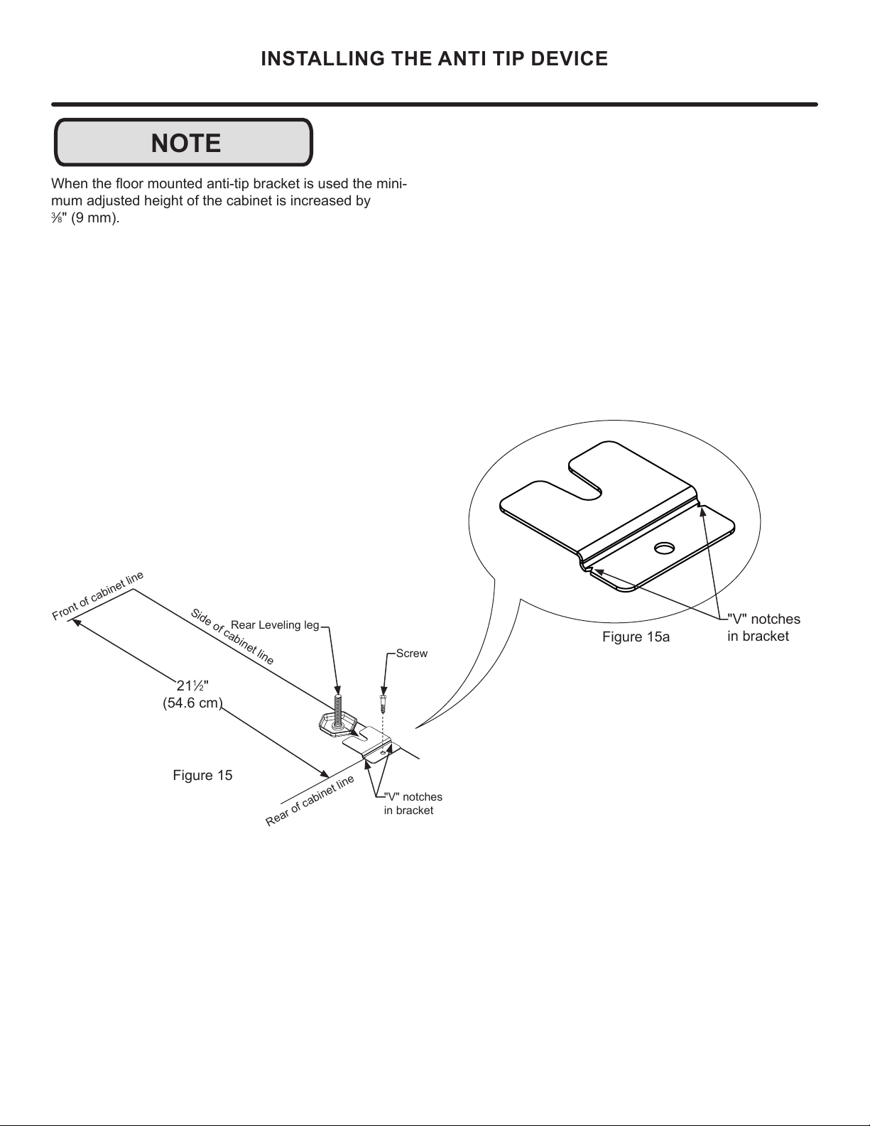
NOTE
INSTALLING THE ANTI TIP DEVICE
-
mum adjusted height of the cabinet is increased by
3
8" (9 mm).
Figure 15a
"V" notches
in bracket
"V" notches
in bracket
Figure 15
21
1
2"
(54.6 cm)
Front of cabinet line
Rear Leveling leg
Side of cabinet line
Rear of cabinet line
Screw
12
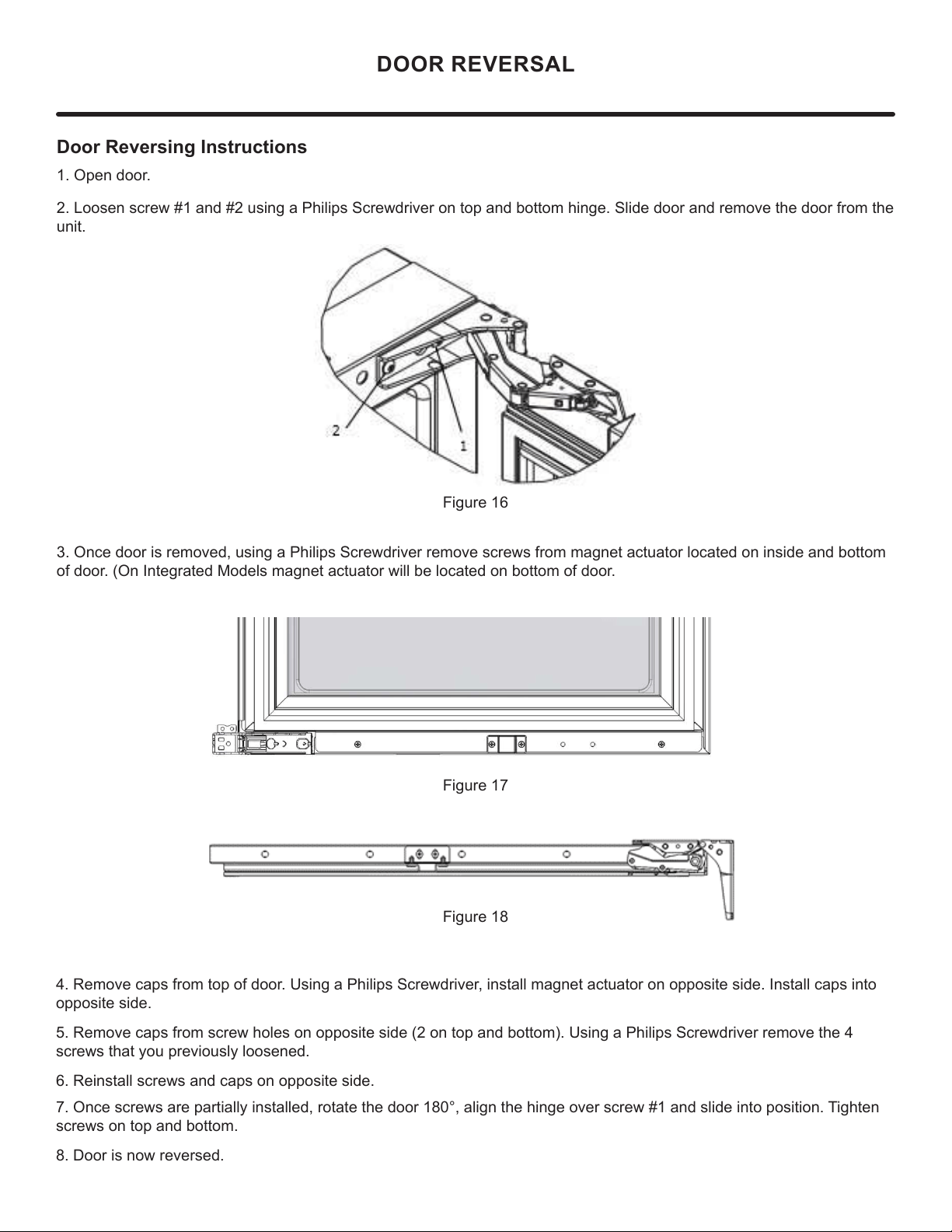
Door Reversing Instructions
1. Open door.
2. Loosen screw #1 and #2 using a Philips Screwdriver on top and bottom hinge. Slide door and remove the door from the
unit.
3. Once door is removed, using a Philips Screwdriver remove screws from magnet actuator located on inside and bottom
of door. (On Integrated Models magnet actuator will be located on bottom of door.
Figure 16
Figure 17
Figure 18
4. Remove caps from top of door. Using a Philips Screwdriver, install magnet actuator on opposite side. Install caps into
opposite side.
5. Remove caps from screw holes on opposite side (2 on top and bottom). Using a Philips Screwdriver remove the 4
screws that you previously loosened.
6. Reinstall screws and caps on opposite side.
7. Once screws are partially installed, rotate the door 180°, align the hinge over screw #1 and slide into position. Tighten
screws on top and bottom.
8. Door is now reversed.
DOOR REVERSAL
13
USING YOUR ELECTRONIC CONTROL
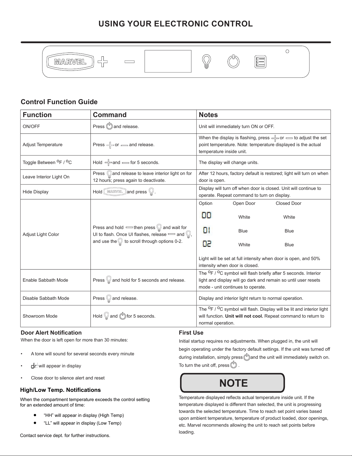
Control Function Guide
Function Command Notes
ON/OFF Press and release. Unit will immediately turn ON or OFF.
Adjust Temperature Press or and release.
When the display is ashing, press or to adjust the set
point temperature. Note: temperature displayed is the actual
temperature inside unit.
Toggle Between
o
F /
o
C Hold and for 5 seconds. The display will change units.
Leave Interior Light On
Press and release to leave interior light on for
12 hours; press again to deactivate.
After 12 hours, factory default is restored; light will turn on when
door is open.
Hide Display Hold and press .
Display will turn o when door is closed. Unit will continue to
operate. Repeat command to turn on display.
Adjust Light Color
Press and hold then press and wait for
UI to ash. Once UI ashes, release and ,
and use the to scroll through options 0-2.
Option Open Door Closed Door
White White
Blue Blue
White Blue
Light will be set at full intensity when door is open, and 50%
intensity when door is closed.
Enable Sabbath Mode Press and hold for 5 seconds and release.
The
o
F /
o
C symbol will ash briey after 5 seconds. Interior
light and display will go dark and remain so until user resets
mode - unit continues to operate.
Disable Sabbath Mode Press and release. Display and interior light return to normal operation.
Showroom Mode Hold and for 5 seconds.
The
o
F /
o
C symbol will ash. Display will be lit and interior light
will function. Unit will not cool. Repeat command to return to
normal operation.
Door Alert Notication
When the door is left open for more than 30 minutes:
• A tone will sound for several seconds every minute
• will appear in display
• Close door to silence alert and reset
First Use
Initial startup requires no adjustments. When plugged in, the unit will
begin operating under the factory default settings. If the unit was turned o
during installation, simply press and the unit will immediately switch on.
To turn the unit o, press .
Temperature displayed reects actual temperature inside unit. If the
temperature displayed is dierent than selected, the unit is progressing
towards the selected temperature. Time to reach set point varies based
upon ambient temperature, temperature of product loaded, door openings,
etc. Marvel recommends allowing the unit to reach set points before
loading.
NOTE
High/Low Temp. Notifications
When the compartment temperature exceeds the control setting
for an extended amount of time:
• “HH” will appear in display (High Temp)
• “LL” will appear in display (Low Temp)
Contact service dept. for further instructions.
14
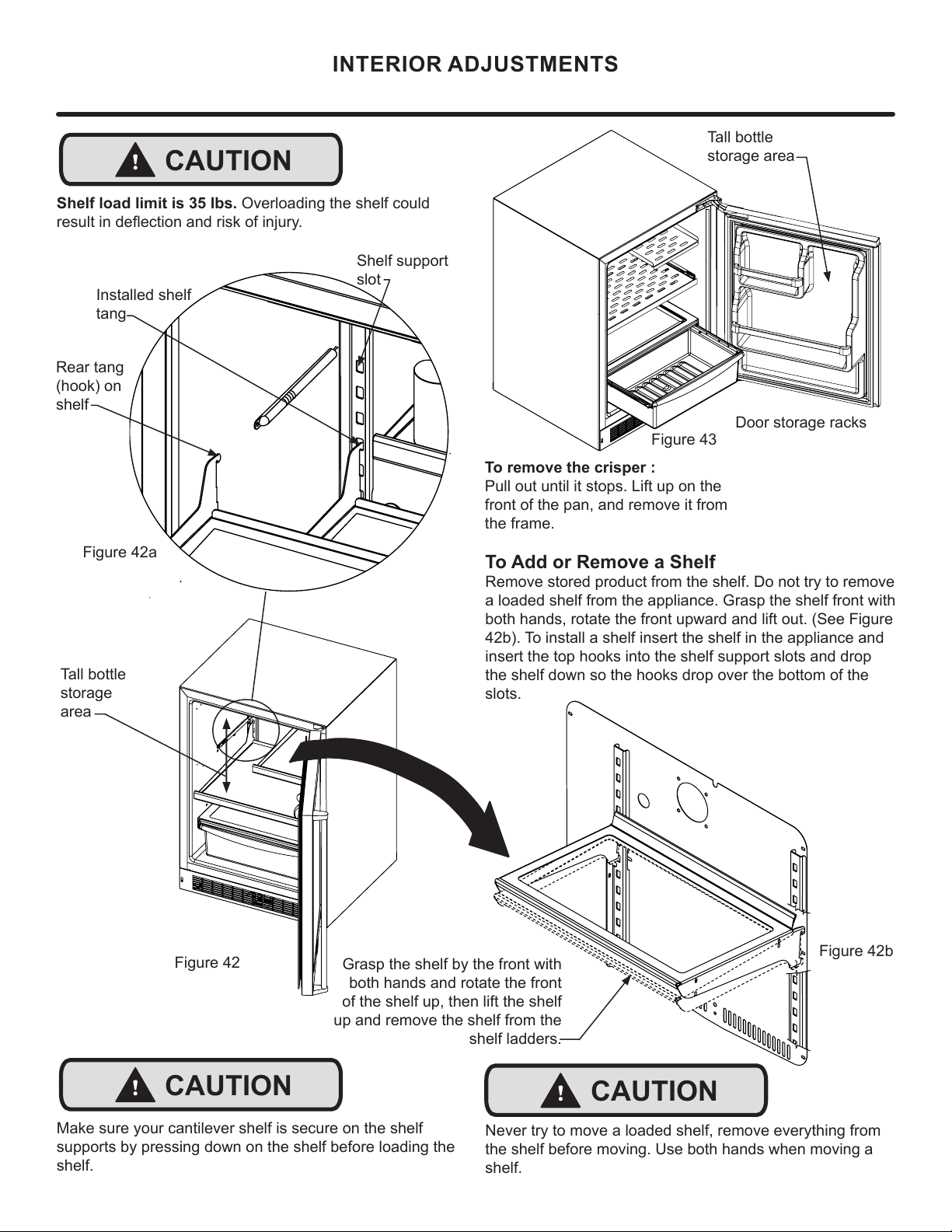
Tall bottle
storage
area
To Add or Remove a Shelf
Remove stored product from the shelf. Do not try to remove
a loaded shelf from the appliance. Grasp the shelf front with
both hands, rotate the front upward and lift out. (See Figure
42b). To install a shelf insert the shelf in the appliance and
insert the top hooks into the shelf support slots and drop
the shelf down so the hooks drop over the bottom of the
slots.
Rear tang
(hook) on
shelf
Shelf support
slot
Installed shelf
tang
Make sure your cantilever shelf is secure on the shelf
supports by pressing down on the shelf before loading the
shelf.
!
CAUTION
Grasp the shelf by the front with
both hands and rotate the front
of the shelf up, then lift the shelf
up and remove the shelf from the
shelf ladders.
!
CAUTION
Never try to move a loaded shelf, remove everything from
the shelf before moving. Use both hands when moving a
shelf.
Figure 42a
Figure 42
Figure 42b
INTERIOR ADJUSTMENTS
To remove the crisper :
Pull out until it stops. Lift up on the
front of the pan, and remove it from
the frame.
Door storage racks
Tall bottle
storage area
Figure 43
Shelf load limit is 35 lbs. Overloading the shelf could
result in deection and risk of injury.
!
CAUTION
15
!
CAUTION
Front Grille
Be sure that nothing obstructs the required air ow open-
ings in front of the cabinet. At least once or twice a year,
brush or vacuum lint and dirt from the front grille area (see
page 8).
SHOCK HAZARD: Disconnect electrical power from the
appliance before cleaning with soap and water.
Cabinet
The painted cabinet can be washed with either a mild soap
and water and thoroughly rinsed with clear water. NEVER
use abrasive scouring cleaners.
Interior
Wash interior compartment with mild soap and water. Do
NOT use an abrasive cleaner, solvent, polish cleaner or
undiluted detergent.
Care of Appliance
1. Avoid leaning on the door, you may bend the door
hinges or tip the appliance.
2. Exercise caution when sweeping, vacuuming or mop-
ping near the front of the appliance. Damage to the
grille can occur.
3. Periodically clean the interior of the appliance as
needed.
4. Periodically check and/or clean the front grille as
needed.
In the Event of a Power Failure
If a power failure occurs, try to correct it as soon as pos-
sible. Minimize the number of door openings while the
power is o so as not to adversely aect the appliance's
temperature.
Light assembly replacement
All models use an LED to illuminate the interior of the ap-
pliance. This component is very reliable, but should it fail,
contact a qualied service technician for replacement of the
LED.
CARE AND CLEANING
16
STAINLESS STEEL MAINTENANCE
Background
Stainless steel does not stain, corrode, or rust as easily as
ordinary steel, but it is not stain or corrosion proof. Stain-
less steels can discolor or corrode if not maintained prop-
erly.
amount of chromium present. It is this chromium that
surface can be damaged or contaminated, which may
result in discoloration, staining, or corrosion of the base
metal.
Care & Cleaning
Routine cleaning of the stainless steel surfaces will serve to
greatly extend the life of your product by removing contami-
nants. This is especially important in coastal areas which
can expose the stainless to severe contaminants such as
It is strongly recommended to periodically inspect and thor-
oughly clean crevices, weld points, under gaskets, rivets,
bolt heads, and any locations where small amounts of liquid
could collect, become stagnant, and concentrate contami-
nates. Additionally, any mounting hardware that is showing
signs of corrosion should be replaced.
Frequency of cleaning will depend upon the installation
location, environmental, and usage conditions.
Choosing a Cleaning Product
The choice of a proper cleaning product is ultimately that
of the consumer, and there are many products from which
to choose. Depending upon the type of cleaning and the
degree of contamination, some products are better than
others.
cleaning of most stainless steel products is to give the sur-
faces a brisk rubbing with a soft cloth soaked in warm water
and a gentle detergent, or mild mixture of ammonia. Rub-
bing should, to the extent possible, follow the polish lines of
the steel, and always insure thorough rinsing after cleaning.
Although some products are called "stainless steel clean-
ers," some may contain abrasives which could scratch the
and some many contain chlorine bleach which will dull,
tarnish or discolor the surface if not completely removed.
After the stainless surfaces have been thoroughly cleaned,
a good quality car wax may be applied to help maintain the
Stainless steel products should never be installed, or stored
in close proximity to chlorine chemicals.
Whichever cleaning product you chose, it should be used
in strict accordance with the instructions of the cleaner
manufacturer.
NOTE
17
ENERGY SAVING TIPS
4. Plug your appliance into a dedicated power circuit. (Not
shared with other appliances).
5. When initially loading your new product, or whenever
large quantities of warm contents are placed within
refrigerated storage compartment, minimize door
openings for the next 12 hours to allow contents to pull
down to compartment set temperature.
6. Maintaining a relatively full storage compartment will
require less appliance run time than an empty compart-
ment.
7. Ensure door closing is not obstructed by contents
stored in your appliance.
8. Allow hot items to reach room temperature before plac-
ing in product.
9. Minimize door openings and duration of door openings.
10. Use the warmest temperature control set temperature
that meets your personal preference and provides the
proper storage for your stored contents.
11. When on vacation or away from home for extended pe-
riods, set the appliance to warmest acceptable tem-
perature for the stored contents.
12. Set the control to the “o” position if cleaning the
appliance requires the door to be open for an extended
period of time.
13. For wine storage products:
When serving temperatures are not required,
return the compartment(s) set temperature to the
ideal red and white wine long term storage tem-
perature of 13°C / 55°F.
The following suggestions will minimize the
cost of operating your refrigeration appliance.
1. Do not install your appliance next to a hot appliance
(cooker, dishwasher, etc.), heating air duct, or other
heat sources.
2. Install product out of direct sunlight.
3. Ensure the front grille vents at front of appliance be-
neath door are not obstructed and kept clean to allow
ventilation for the refrigeration system to expel heat.
18
Vacation/Holiday, Prolonged Shutdown
The following steps are recommended for periods of ex-
tended non-use:
EXTENDED NON-USE
1. Remove all consumable content from the unit.
2. Disconnect the power cord from its outlet/socket and
leave it disconnected until the unit is returned to service.
3. If ice is on the evaporator, allow ice to thaw naturally.
4. Clean and dry the interior of the unit. Ensure all water
has been removed from the unit.
5. The door must remain open to prevent formation of mold
and mildew. Open door a minimum of 2" (50 mm) to provide
the necessary ventilation.
Winterization
If the unit will be exposed to temperatures of 40° F (5° C) or
less, the steps above must be followed.
For questions regarding winterization, please call Marvel at
(616) 754-5601.
!
CAUTION
Damage caused by freezing temperatures is not covered
by the warranty.
19
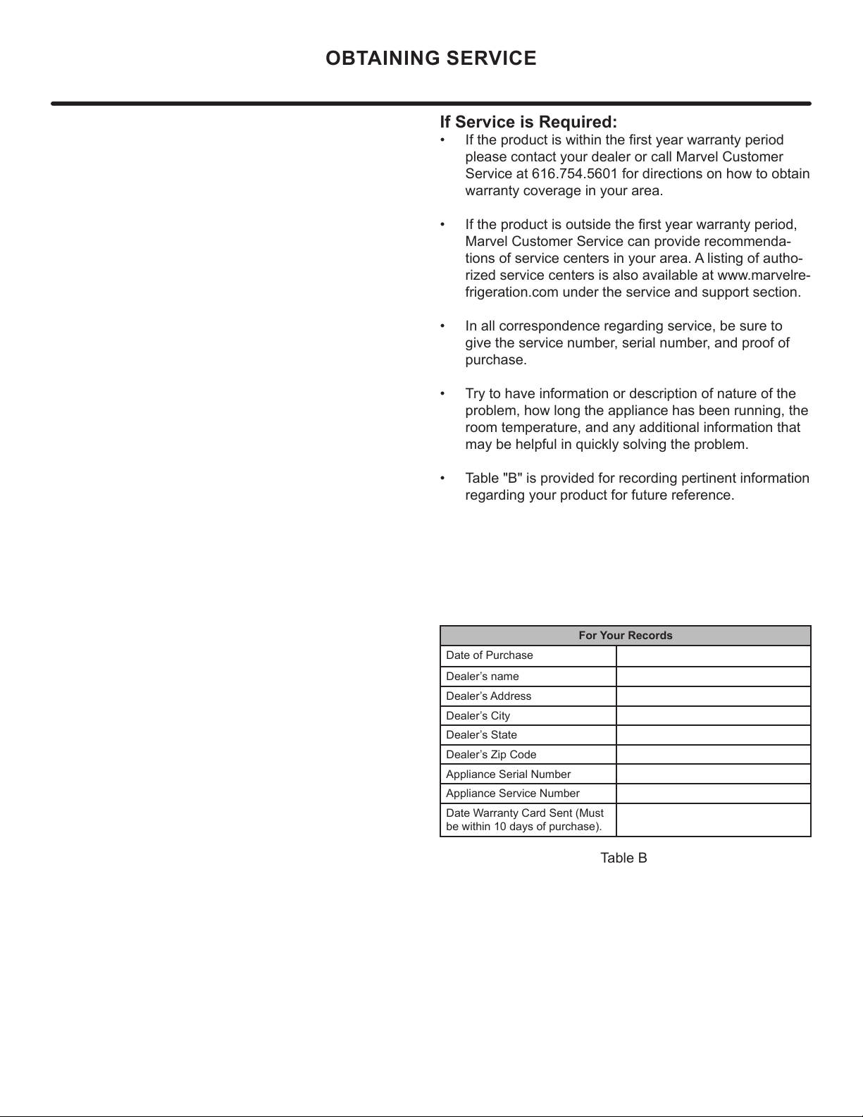
If Service is Required:
• If the product is within the rst year warranty period
please contact your dealer or call Marvel Customer
Service at 616.754.5601 for directions on how to obtain
warranty coverage in your area.
• If the product is outside the rst year warranty period,
Marvel Customer Service can provide recommenda-
tions of service centers in your area. A listing of autho-
rized service centers is also available at www.marvelre-
frigeration.com under the service and support section.
• In all correspondence regarding service, be sure to
give the service number, serial number, and proof of
purchase.
• Try to have information or description of nature of the
problem, how long the appliance has been running, the
room temperature, and any additional information that
may be helpful in quickly solving the problem.
• Table "B" is provided for recording pertinent information
regarding your product for future reference.
For Your Records
Date of Purchase
Dealer’s name
Dealer’s Address
Dealer’s City
Dealer’s State
Dealer’s Zip Code
Appliance Serial Number
Appliance Service Number
Date Warranty Card Sent (Must
be within 10 days of purchase).
Table B
OBTAINING SERVICE
20
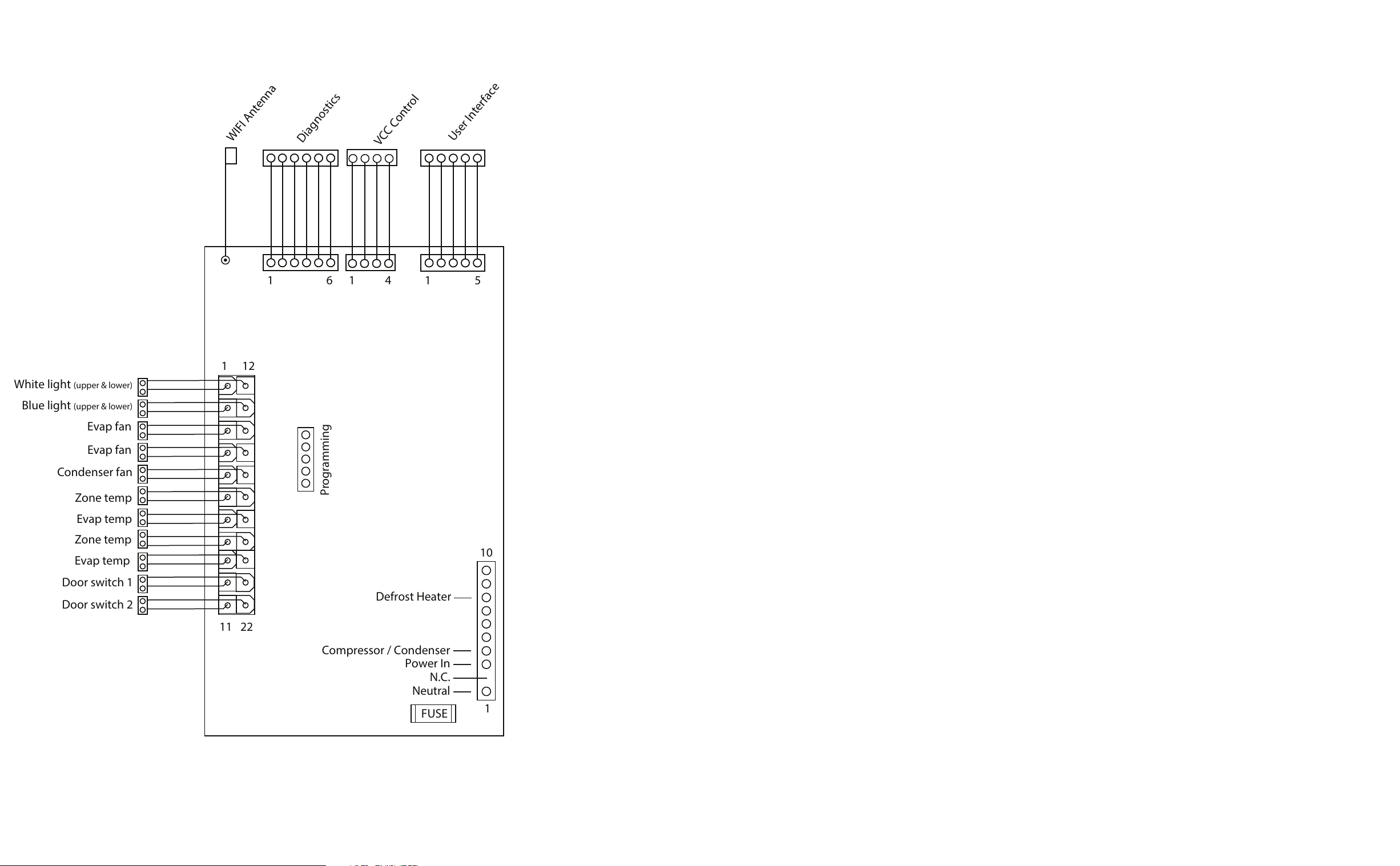
Power In
Compressor / Condenser
N.C.
Neutral
FUSE
11
10
22
1
1
12
White light
(upper & lower)
Blue light (upper & lower)
Evap fan
Evap fan
Condenser fan
Zone temp
Door switch 1
Door switch 2
Evap temp
Zone temp
Evap temp
Programming
WIFI Antenna
Diagnostics
VCC Control
User Interface
1 51 6 1 4
Defrost Heater
21
Product Liability
E
V
G
The original refrigeration experts since 1892.
22

Warranty Claims
2021 04 23 050H
1 I I I
Year
Warranty Claims
D
ay
Factory
use Only
M
Month
23
1848
16
25
7
22
32
31
23 3
15
20
1719
30
6
9
21
14
28
33
1
13
5
12
27
2
11
26
24
* NOT PICTURED
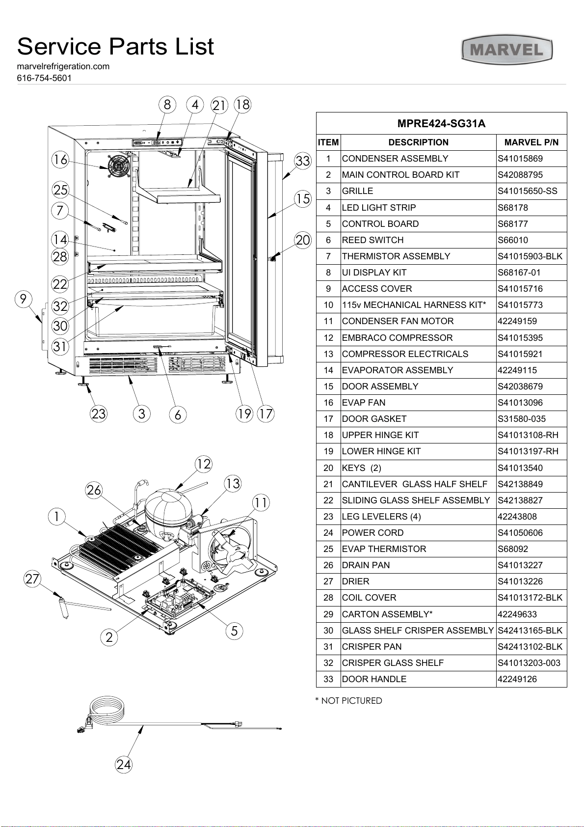
MPRE424-SG31A
ITEM
DESCRIPTION
MARVEL P/N
1
CONDENSER ASSEMBLY
S41015869
2
MAIN CONTROL BOARD KIT
S42088795
3
GRILLE
S41015650-SS
4
LED LIGHT STRIP
S68178
5
CONTROL BOARD
S68177
6
REED SWITCH
S66010
7
THERMISTOR ASSEMBLY
S41015903-BLK
8
UI DISPLAY KIT
S68167-01
9
ACCESS COVER
S41015716
10
115v MECHANICAL HARNESS KIT*
S41015773
11
CONDENSER FAN MOTOR
42249159
12
EMBRACO COMPRESSOR
S41015395
13
COMPRESSOR ELECTRICALS
S41015921
14
EVAPORATOR ASSEMBLY
42249115
15
DOOR ASSEMBLY
S42038679
16
EVAP FAN
S41013096
17
DOOR GASKET
S31580-035
18
UPPER HINGE KIT
S41013108-RH
19
LOWER HINGE KIT
S41013197-RH
20
KEYS (2)
S41013540
21
CANTILEVER GLASS HALF SHELF
S42138849
22
SLIDING GLASS SHELF ASSEMBLY
S42138827
23
LEG LEVELERS (4)
42243808
24
POWER CORD
S41050606
25
EVAP THERMISTOR
S68092
26
DRAIN PAN
S41013227
27
DRIER
S41013226
28
COIL COVER
S41013172-BLK
29
CARTON ASSEMBLY*
42249633
30
GLASS SHELF CRISPER ASSEMBLY
S42413165-BLK
31
CRISPER PAN
S42413102-BLK
32
CRISPER GLASS SHELF
S41013203-003
33
DOOR HANDLE
42249126
Service Parts List
marvelrefrigeration.com
616-754-5601
24
Ordering Replacement Parts
O
"
"
6
6
6
M
M
M
M
m.
Ordering Replacement Parts
25
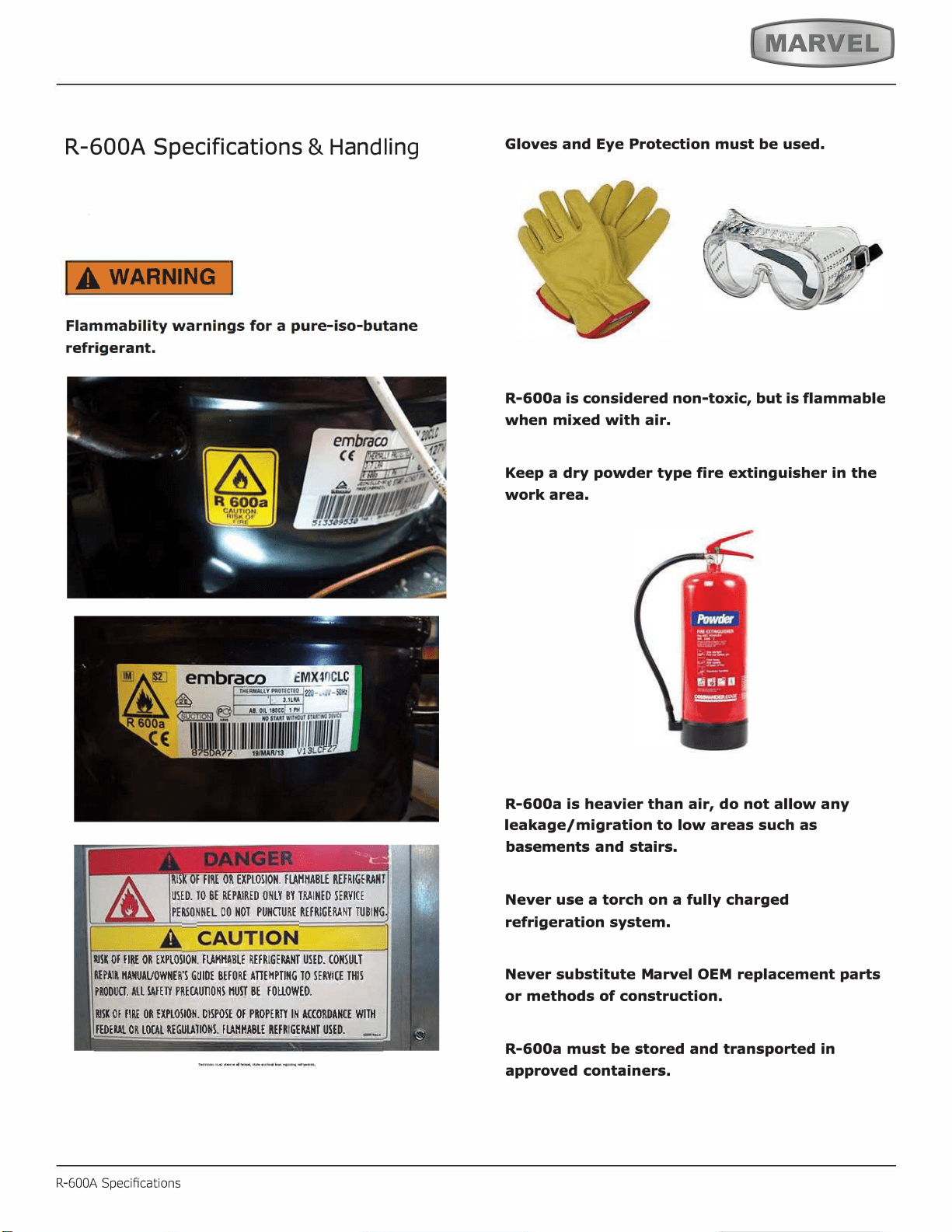
R-600A Specifications
&
H
an
dl
in
g
R-600A Specications
,
.
'
26
IA WARNING I
27

SYSTEM REPAIR
R-600A Specications
LEAK DETECTION
28
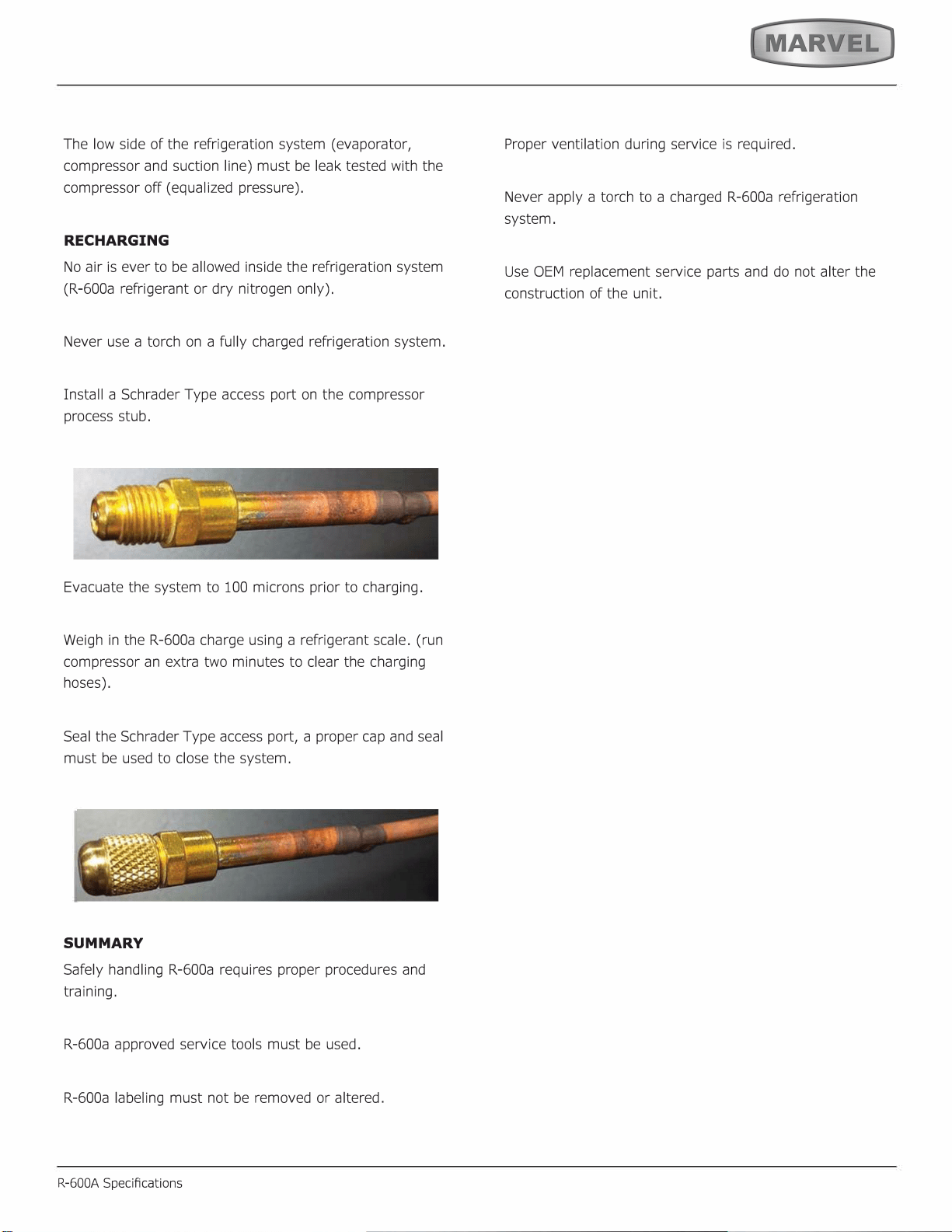
RECHARGING
SUMMARY
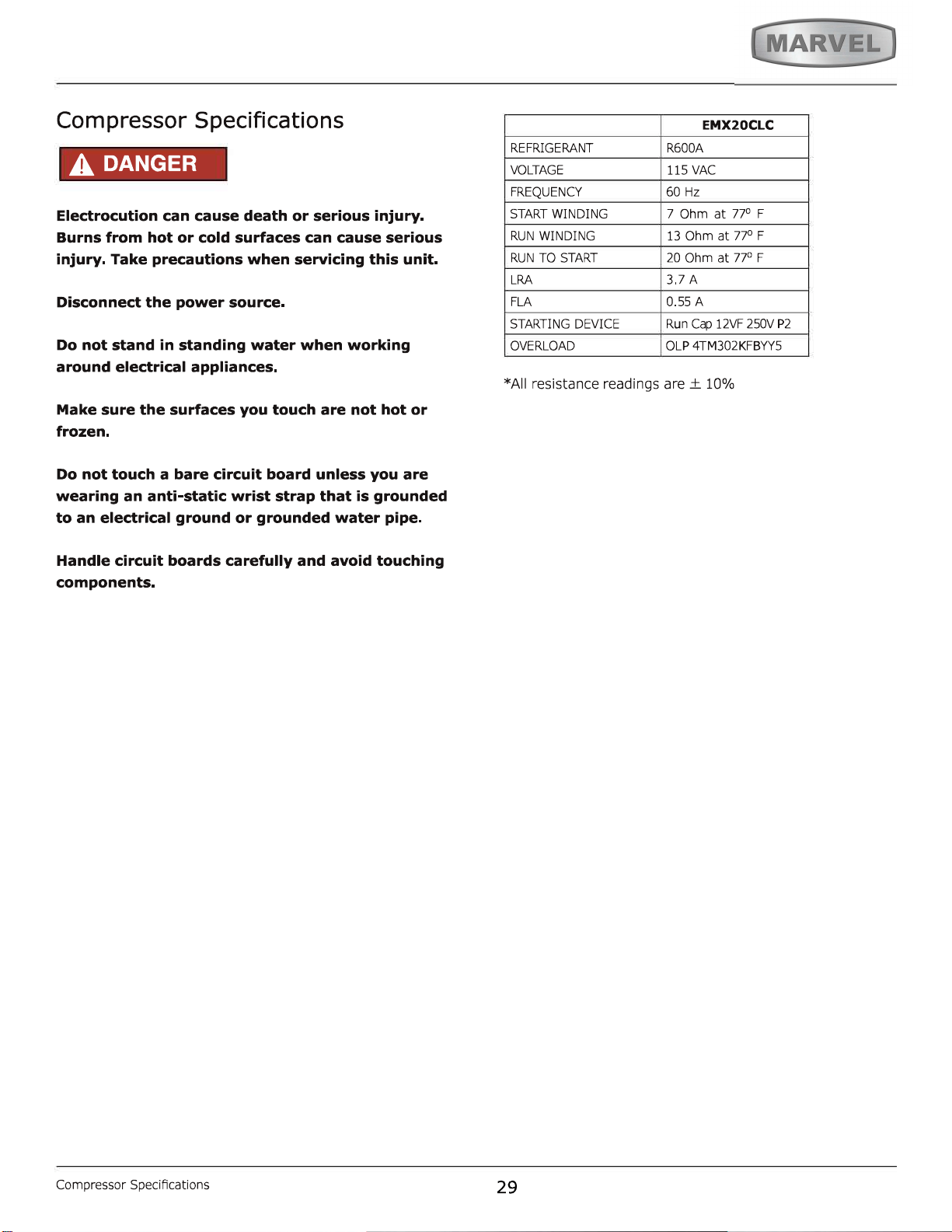
29
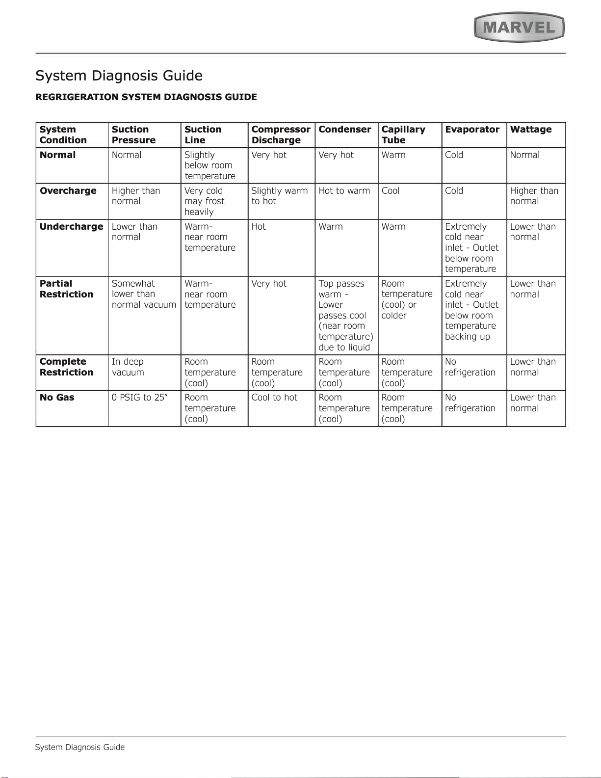
System Diagnosis Guide
System Diagnosis Guide
30
31
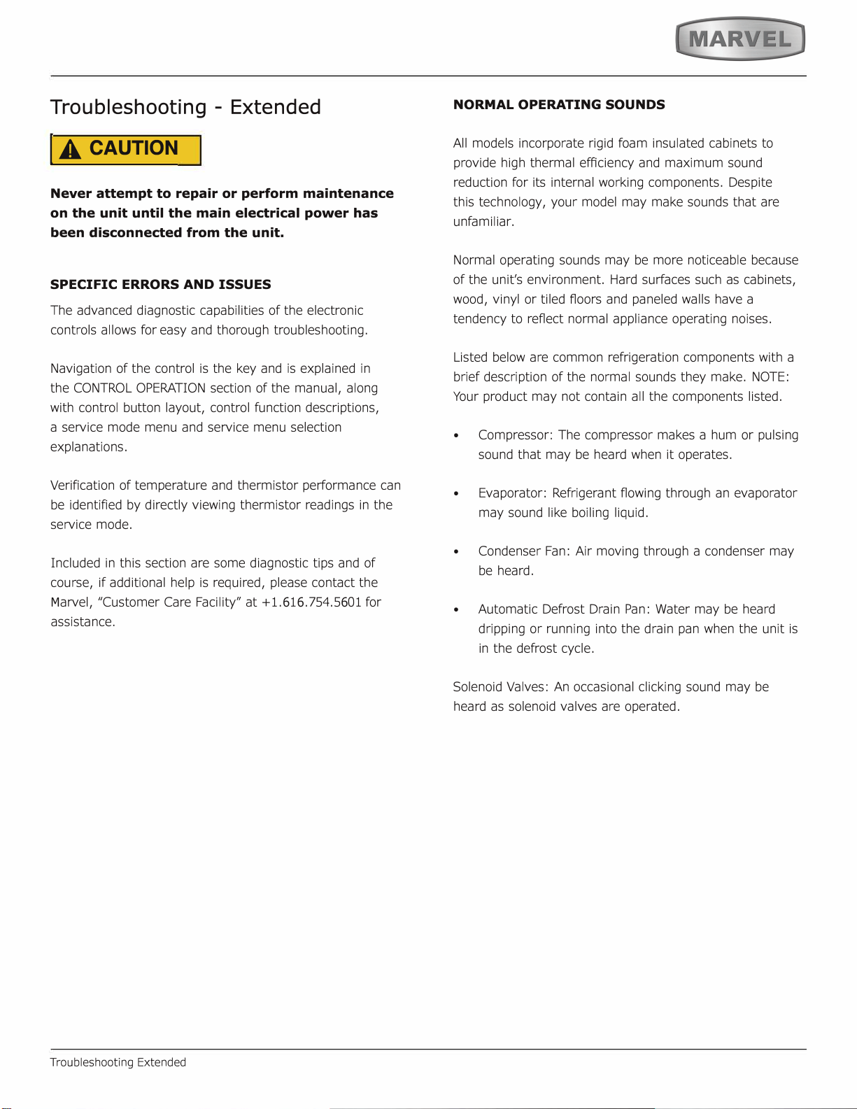
Troubleshooting - Ex
tended
I A
CAUTION
M
6
6
6
Troubleshooting Extended
•
•
•
•
32
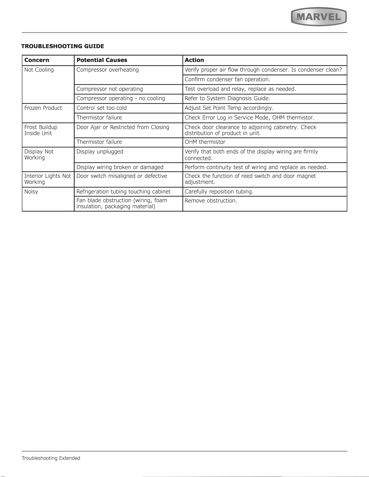
TROUBLESHOOTING GUIDE
Concern
Potential Causes
Action
Troubleshooting Extended
33
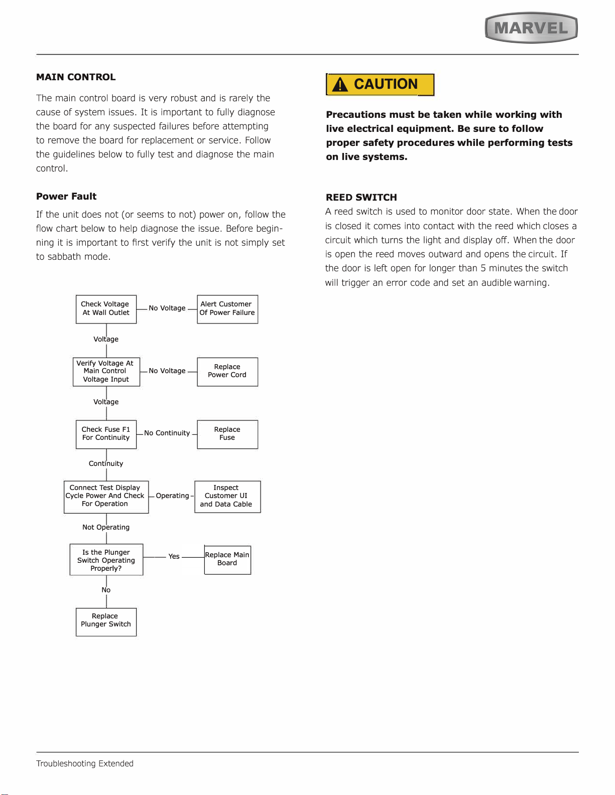
MAIN CONTROL
Power Fault
Troubleshooting Extended
A
Precautions must be taken while working with
live electrical equipment. Be sure to follow
proper safety procedures while performing tests
on live systems.
REE
D
SWITCH
34
Control Operation-Service
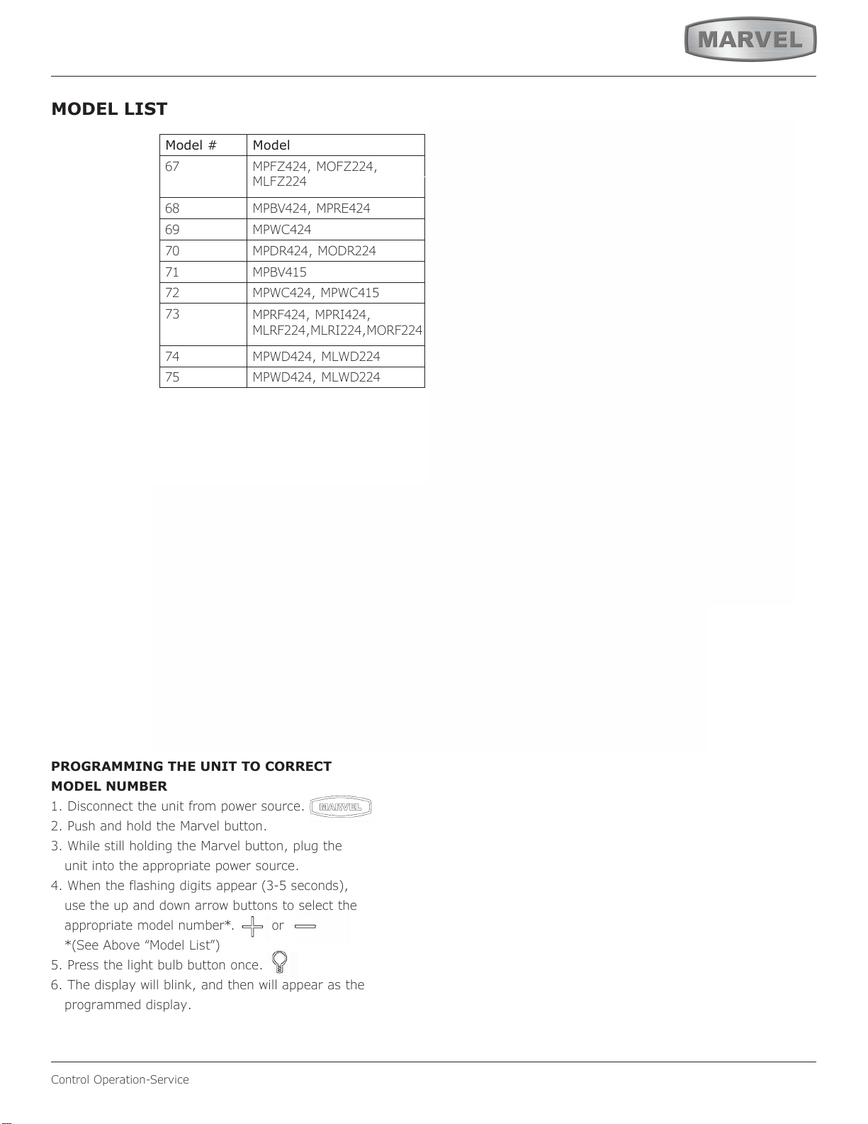
MODEL LIST
Model # Model
67
MPFZ424, MOFZ224,
MLFZ224
68
MPBV424, MPRE424
69 MPWC424
70
MPDR424, MODR224
71 MPBV415
72
MPWC424, MPWC415
73
MPRF424, MPRI424,
MLRF224,MLRI224,MORF224
74
MPWD424, MLWD224
75
MPWD424, MLWD224
17 *HRE315-***1A
18 *HRE315-***2A
19 *HRE318-***1A
20 *HRE324-***1A
21 *HRE324-***2A
22 *HRE336-***1A
23 *HRE515-***1A
24 *HRE515-***2A
25 *HRE524-***1A
26 *HRE524-***2A
27 *HRE324-***1A
28 *HRE324-***2A
29 *HKR524-***1A
30 *HKR524-***2A
31 *HWC315-***2A
32 *HWC315-***1A
33 *HWC318-***1A
34 *HWC324-***2A
35 *HWC324-***1A
36 *HWC515-***2A
37 *HWC515-***1A
38 *HWC524-***1A
39 *HWC524-***2A
40 *HWC336-***1A
41 *HBD324-***1A
42 *HBD324-***2A
43 *HBD524-***1A
44 *HBD524-***2A
45 *HWD324-***2A
46 *HWD324-***1A
47 *HWD524-***2A
48 *HWD524-***1A
49 *HRF124-***2A
50 *HRF124-***1A
51 *HRI124-***2A
52 *HRI124-***1A
53 Nugget R134A
54 Grid Ice
55 Medical Refrigerator
56 Full size
57 Nugget R600
PROGRAMMING THE UNIT TO CORRECT
MODEL NUMBER
1. Disconnect the unit from power source.
2. Push and hold the Marvel button.
3. While still holding the Marvel button, plug the
unit into the appropriate power source.
4. When the flashing digits appear (3-5 seconds),
use the up and down arrow buttons to select the
appropriate model number*. or
*(See Above “Model List”)
5. Press the light bulb button once.
6. The display will blink, and then will appear as the
programmed display.
35

USER GUIDE
u-line.com
Control Operation-Service
Program Model Relay 1 Relay 2 Relay 3 Relay 4 Relay 5 Relay 6 DC1 DC2 DC3 DC4 DC5
53
Nugget Ice, R134 Comp/Fan - Dump Valve Reservoir Fill Auger Water Main Light 1 Light 2 - - Cond Fan
57
Nugget Ice, R600 Water Main Water Dis-
pense
Dump Valve Reservoir Fill Auger Cond Fan Light 1 Light 2 - - Cond Fan
11
Clear Ice, 3 Class Compressor Water Dis-
pense
Circ Pump Water Inlet Hot Gas
Valve
Cond Fan Light 1 Light 2 - - Cond Fan
01
**BV315-***1A Compressor - - - - - Light 1 Light 2 Evap Fan - Cond Fan
03
**BV318-***1A Compressor - - - - - Light 1 Light 2 Evap Fan - Cond Fan
04
**BV324-***1A Compressor - - - - - Light 1 Light 2 Evap Fan - Cond Fan
06
**BV336-***1A Compressor Top/Left Valve Bot/Right Valve - - - Light 1 Light 2 Evap Fan Evap Fan 2 Cond Fan
07
**BV515-***1A Compressor - - - - - Light 1 Light 2 Evap Fan - Cond Fan
09
**BV524-***1A Compressor - - - - - Light 1 Light 2 Evap Fan -
Cond Fan
13
**DR324-***1A Compressor Mullion Heater - - - - Light 1 Light 2 Evap Fan Evap Fan 2 Cond Fan
15
**FZ324-***1A Compressor - - - Heater Cond Fan Light 1 Light 2 Evap Fan - Cond Fan
17
**RE315-***1A Compressor - - - - - Light 1 Light 2 Evap Fan - Cond Fan
19
**RE318-***1A Compressor - - - - - Light 1 Light 2 Evap Fan - Cond Fan
20
**RE324-***1A Compressor - - - - - Light 1 Light 2 Evap Fan - Cond Fan
22
**RE336-***1A Compressor Top/Left Valve Bot/Right Valve - - - Light 1 Light 2 Evap Fan Evap Fan 2 Cond Fan
23
**RE515-***1A Compressor - - - - - Light 1 Light 2 Evap Fan - Cond Fan
25
**RE524-***1A Compressor - - - - - Light 1 Light 2 Evap Fan - Cond Fan
27
**RE324-***1A Compressor - - - - - Light 1 Light 2 Evap Fan - Cond Fan
29
**KR524-***1A Compressor - - - - - Light 1 Light 2 Evap Fan - Cond Fan
32
**WC315-***1A Compressor
- - - - - Light 1 Light 2 Evap Fan - Cond Fan
33
**WC318-***1A Compressor - - - - - Light 1 Light 2 Evap Fan - Cond Fan
35
**WC324-***1A Compressor - - - - - Light 1 Light 2 Evap Fan - Cond Fan
37
**WC515-***1A Compressor - - - - - Light 1 Light 2 Evap Fan - Cond Fan
38
**WC524-***1A Compressor - - - - - Light 1 Light 2 Evap Fan - Cond Fan
40
**WC336-***1A Compressor Top/Left Valve Bot/Right Valve - - - Light 1 Light 2 Evap Fan Evap Fan 2 Cond Fan
41
**BD324-***1A Compressor Top/Left Valve Bot/Right Valve - - - Light 1 Light 2 Evap Fan Evap Fan 2 Cond Fan
43
**BD524-***1A Compressor Top/Left Valve Bot/Right Valve - - - Light 1 Light 2 Evap Fan Evap Fan 2 Cond Fan
46
**WD324-***1A Compressor Top/Left Valve Bot/Right Valve - - - Light 1 Light 2 Evap Fan Evap Fan 2 Cond Fan
48
**WD524-***1A Compressor Top/Left Valve Bot/Right Valve - - - Light 1 Light 2 Evap Fan Evap Fan 2 Cond Fan
50
**RF124-***1A Compressor - - Pan Defrost
Heater
Cond Fan Light 1 Light 2 Evap Fan - Cond Fan
52
**RI124-***1A Compressor Icemaker 2 Icemaker 1 Pan Defrost
Heater
Cond Fan Light 1 Light 2 Evap Fan - Cond Fan
Relay / Output Chart
36
Control Operation-Service
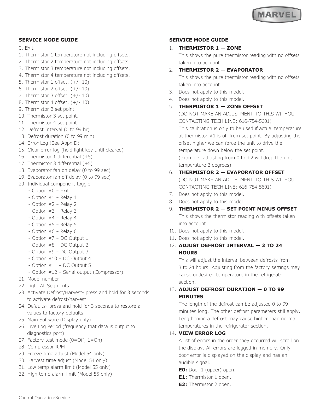
SERVICE MODE GUIDE SERVICE MODE GUIDE
([LW
7KHUPLVWRUWHPSHUDWXUHQRWLQFOXGLQJRɞVHWV
7KHUPLVWRUWHPSHUDWXUHQRWLQFOXGLQJRɞVHWV
7KHUPLVWRUWHPSHUDWXUHQRWLQFOXGLQJRɞVHWV
7KHUPLVWRUWHPSHUDWXUHQRWLQFOXGLQJRɞVHWV
7KHUPLVWRURɞVHW
7KHUPLVWRURɞVHW
7KHUPLVWRURɞVHW
7KHUPLVWRURɞVHW
9. Thermistor 2 set point
7KHUPLVWRUVHWSRLQW
11. Thermistor 4 set point.
'HIURVW,QWHUYDOWRKU
'HIURVWGXUDWLRQWRPLQ
(UURU/RJ6HH$SS['
&OHDUHUURUORJKROGOLJKWNH\XQWLOFOHDUHG
7KHUPLVWRUGLɞHUHQWLDO
7KHUPLVWRUGLɞHUHQWLDO
(YDSRUDWRUIDQRQGHOD\WRVHF
(YDSRUDWRUIDQRɞGHOD\WRVHF
,QGLYLGXDOFRPSRQHQWWRJJOH
2SWLRQȊ([LW
2SWLRQȊ5HOD\
2SWLRQȊ5HOD\
2SWLRQȊ5HOD\
2SWLRQȊ5HOD\
2SWLRQȊ5HOD\
2SWLRQȊ5HOD\
2SWLRQȊ'&2XWSXW
2SWLRQȊ'&2XWSXW
2SWLRQȊ'&2XWSXW
2SWLRQȊ'&2XWSXW
2SWLRQȊ'&2XWSXW
2SWLRQȊ6HULDORXWSXW&RPSUHVVRU
21. Model number
22. Light All Segments
$FWLYDWH'HIURVW+DUYHVWSUHVVDQGKROGIRUVHFRQGV
WRDFWLYDWHGHIURVWKDUYHVW
24. Defaults- press and hold for 3 seconds to restore all
values to factory defaults.
0DLQ6RIWZDUH'LVSOD\RQO\
/LYH/RJ3HULRGIUHTXHQF\WKDWGDWDLVRXWSXWWR
GLDJQRVWLFVSRUW
)DFWRU\WHVWPRGH 2ɞ 2Q
&RPSUHVVRU530
)UHH]HWLPHDGMXVW0RGHORQO\
+DUYHVWWLPHDGMXVW0RGHORQO\
/RZWHPSDODUPOLPLW0RGHORQO\
+LJKWHPSDODUPOLPLW0RGHORQO\
THERMISTOR 1 — ZONE
7KLVVKRZVWKHSXUHWKHUPLVWRUUHDGLQJZLWKQRRIIVHWV
WDNHQLQWRDFFRXQW
THERMISTOR 2 — EVAPORATOR
7KLVVKRZVWKHSXUHWKHUPLVWRUUHDGLQJZLWKQRRIIVHWV
WDNHQLQWRDFFRXQW
Does not apply to this model.
Does not apply to this model.
THERMISTOR 1 — ZONE OFFSET
'21270$.($1$'-8670(17727+,6:,7+287
&217$&7,1*7(&+/,1(
This calibration is only to be used if actualWHPSHUDWXUH
DWWKHUPLVWRULVRIIIURPVHWSRLQW%\DGMXVWLQJWKH
RIIVHWKLJKHUZHFDQIRUFHWKHXQLWto drive the
temperature down below the set point.
H[DPSOHDGMXVWLQJIURPWRZLOOGURSWKHXQLW
WHPSHUDWXUHGHJUHHV
THERMISTOR 2 — EVAPORATOR OFFSET
'21270$.($1$'-8670(17727+,6:,7+287
&217$&7,1*7(&+/,1(
Does not apply to this model.
Does not apply to this model.
THERMISTOR 2 — SET POINT MINUS OFFSET
7KLVVKRZVWKHWKHUPLVWRUUHDGLQJZLWKRIIVHWVWDNHQ
into account.
'RHVQRWDSSO\WRWKLVPRGHO
Does not apply to this model.
ADJUST DEFROST INTERVAL — 3 TO 24
HOURS
7KLVZLOODGMXVWWKHLQWHUYDOEHWZHHQGHIURVWVIURP
WRKRXUV$GMXVWLQJIURPWKHIDFWRU\VHWWLQJVmay
cause undesired temperature in the refrigerator
section.
ADJUST DEFROST DURATION — 0 TO 99
MINUTES
7KHOHQJWKRIWKHGHIURVWFDQEHDGMXVWHGWR
minutes long. The other defrost parameters still apply.
Lengthening a defrost may cause higher than normal
temperatures in the refrigerator section.
VIEW ERROR LOG
A list of errors in the order they occurred will scrollon
the display. All errors are logged in memory. Only
door error is displayed on the display and has an
audible signal.
E0:'RRUXSSHURSHQ
E1: Thermistor 1 open.
E2: Thermistor 2 open.
37
Control Operation-Service
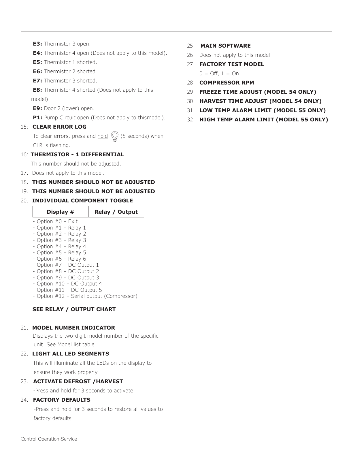
E3: Thermistor 3 open.
E4:7KHUPLVWRURSHQ'RHVQRWDSSO\WRWKLVPRGHO
E5: Thermistor 1 shorted.
E6: Thermistor 2 shorted.
E7: Thermistor 3 shorted.
E8: 7KHUPLVWRUVKRUWHG'RHVQRWDSSO\WRWKLV
PRGHO
E9:'RRUORZHURSHQ
P1:3XPS&LUFXLWRSHQ'RHVQRWDSSO\WRWKLVPRGHO
15: CLEAR ERROR LOG
To clear errors, press and hold
VHFRQGVZKHQ
&/5LVɠDVKLQJ
16: THERMISTOR - 1 DIFFERENTIAL
7KLVQXPEHUVKRXOGQRWEHDGMXVWHG
17. Does not apply to this model.
18. THIS NUMBER SHOULD NOT BE ADJUSTED
19. THIS NUMBER SHOULD NOT BE ADJUSTED
INDIVIDUAL COMPONENT TOGGLE
21. MODEL NUMBER INDICATOR
'LVSOD\VWKHWZRGLJLWPRGHOQXPEHURIWKHVSHFLɟF
unit. See Model list table.
22. LIGHT ALL LED SEGMENTS
This will illuminate all the LEDs on the display to
HQVXUHWKH\ZRUNSURSHUO\
23. ACTIVATE DEFROST /HARVEST
-Press and hold for 3 seconds to activate
24.
FACTORY DEFAULTS
-Press and hold for 3 seconds to restore all values to
factory defaults
25. MAIN SOFTWARE
26.
Does not apply to this model
27.
FACTORY TEST MODEL
2ɞ 2Q
28.
COMPRESSOR RPM
29.
FREEZE TIME ADJUST (MODEL 54 ONLY)
HARVEST TIME ADJUST (MODEL 54 ONLY)
31.
LOW TEMP ALARM LIMIT (MODEL 55 ONLY)
32.
HIGH TEMP ALARM LIMIT (MODEL 55 ONLY)
Display # Relay / Output
2SWLRQȊ([LW
2SWLRQȊ5HOD\
2SWLRQȊ5HOD\
2SWLRQȊ5HOD\
2SWLRQȊ5HOD\
2SWLRQȊ5HOD\
2SWLRQȊ5HOD\
2SWLRQȊ'&2XWSXW
2SWLRQȊ'&2XWSXW
2SWLRQȊ'&2XWSXW
2SWLRQȊ'&2XWSXW
2SWLRQȊ'&2XWSXW
2SWLRQȊ6HULDORXWSXW&RPSUHVVRU
SEE RELAY / OUTPUT CHART
38
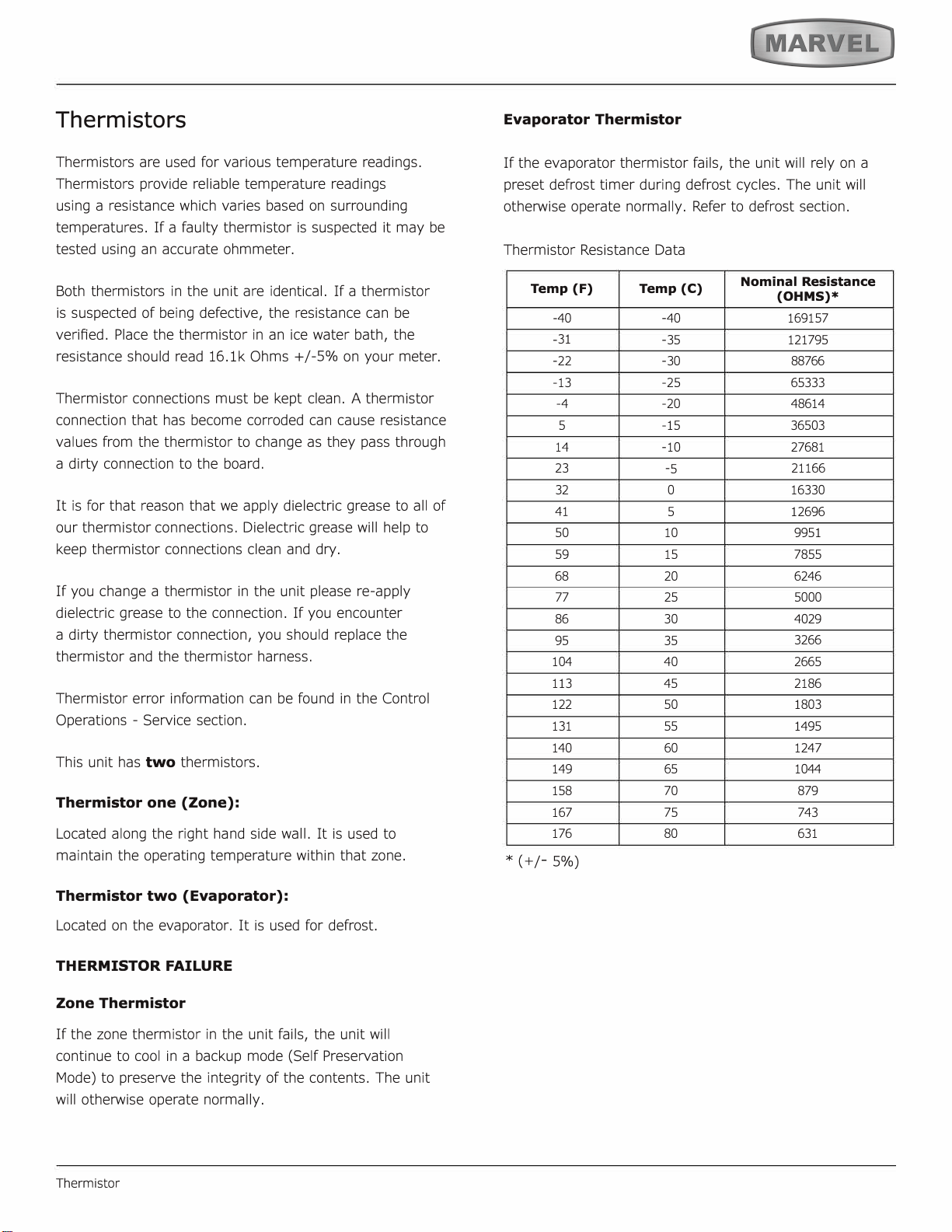
Thermistors
two
Thermistor one (Zone):
Thermistor two (Evaporator):
THERMISTOR FAILURE
Zone Thermistor
Evaporator Thermistor
Temp (F)
Temp (C)
Nominal Resistance
(OHMS)*
77
39
Defrost
Defrost
This unit defrosts every 4 hours of compressor runtime for 45 minutes. If you have verified that the unit does
not have an ambient air leak, utilize the Control Operation - Service section and adjust unit to defrost every
3 hours for 60 minutes. Also, adjust the #2 thermistor to -4 instead of 0.
40
Remove Fan and Cover
Remove Fan and Cover
CONVECTION COOLING
This unit is equipped with an advanced convection cooling
system. Convection cooling stabilizes cabinet temperature,
cools product faster and increases energy eciency.
Evaporator Fan
The evaporator fan is responsible for circulating warm air
from the refrigeration zone, past the evaporator and back
into the refrigerated zone.
The evaporator fan is factory set to have a 1 minute delay
at the beginning of a cooling cycle. This delay gives the
evaporator time to cool properly before warm air is passed
over it. The fan will continue to run for an additional 2
minutes at the end of a cooling cycle. Fan delay times can
be modied through the service menu.
Evaporator fan operation is also determined by door switch
state. If the door switch circuit opens, the fan will stop.
When the door switch circuit is closed the fan will either
continue running with the cooling cycle, or if not currently
cooling, the fan will run for 1 minute to circulate air and
clear any condensation that may have appeared on glass
doors and shelves.
Note: If the unit is set to sabbath mode, the evaporator
fan will no longer respond to the state of the door switch.
In order to operate eciently, the evaporator fan blade
and vents should be unobstructed and free of any dust
buildup.
Evaporator Fan Replacement
Should the evaporator fan need to be replaced follow the
steps below.
1. Remove any product from the unit.
2. Remove unit from cabinetry to access rear.
3. Disconnect power to the unit.
4. Remove back panel from unit.
5. Disconnect fan electrical connection at rear of unit.
6. Remove insulating foam from refrigerant line pass-
through hole as needed to gain clearance for fan plug.
7. Remove internal shelving.
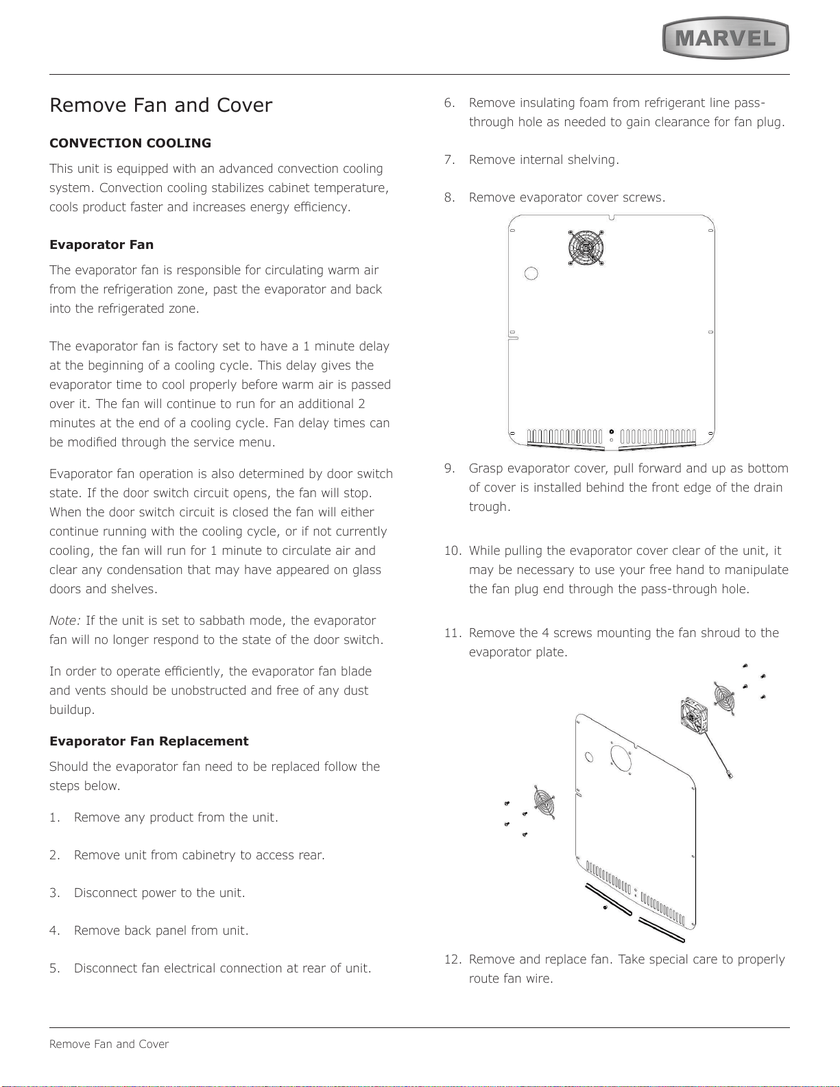
8. Remove evaporator cover screws.
9. Grasp evaporator cover, pull forward and up as bottom
of cover is installed behind the front edge of the drain
trough.
10. While pulling the evaporator cover clear of the unit, it
may be necessary to use your free hand to manipulate
the fan plug end through the pass-through hole.
11. Remove the 4 screws mounting the fan shroud to the
evaporator plate.
12. Remove and replace fan. Take special care to properly
route fan wire.
Air Flow
41
Remove Fan and Cover
NOTICE
Fan must be oriented to pull air in through lower
evaporator cover vents and push air out at fan
mounting location.
13. Installation is the reverse of removal.
14. Care must be taken to assure the bottom of the
evaporator cover is reinstalled behind the front edge of
the train trough.
15. Use sealant gum to seal any openings at rear of unit
before replacing rear cover.
16. Reinstall unit taking care to level, space and secure as
found.
42
HOUSEHOLD PRODUCT WARRANTY
Marvel Refrigeration (Marvel) Limited Warranty
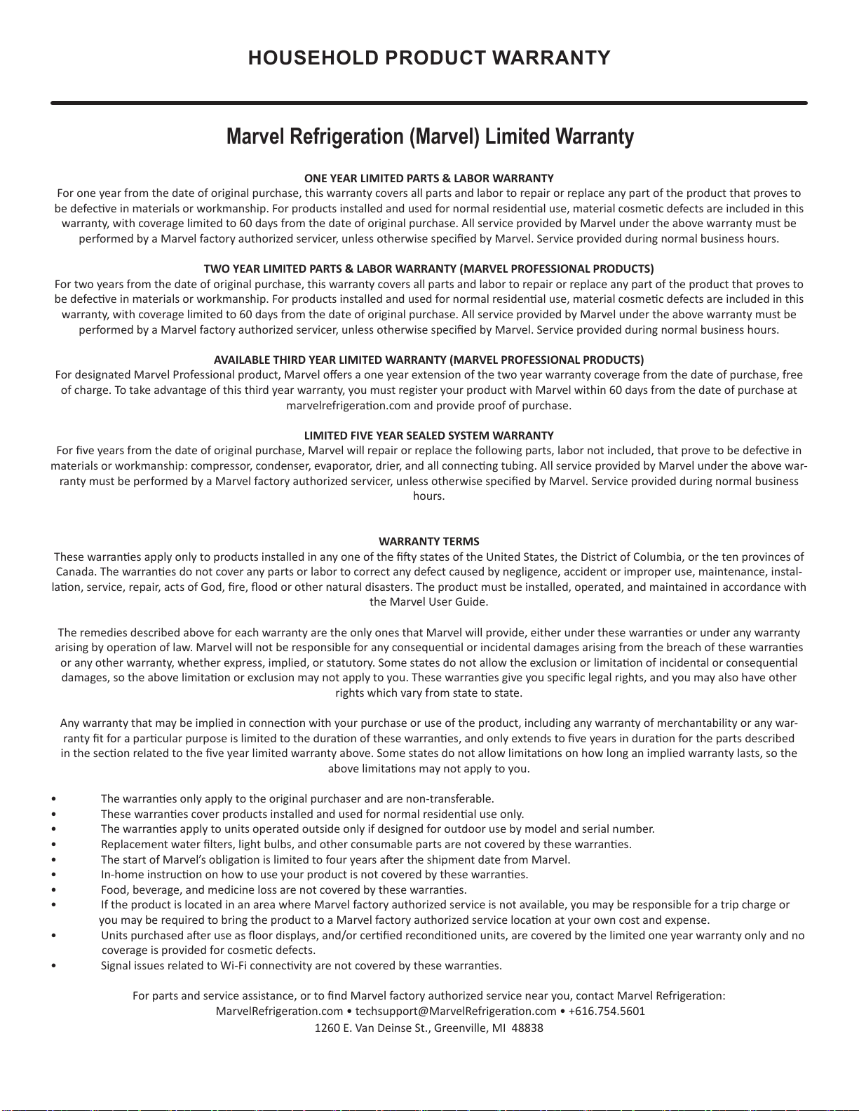
ONE YEAR LIMITED PARTS & LABOR WARRANTY
For one year from the date of original purchase, this warranty covers all parts and labor to repair or replace any part of the product that proves to
be defecve in materials or workmanship. For products installed and used for normal residenal use, material cosmec defects are included in this
warranty, with coverage limited to 60 days from the date of original purchase. All service provided by Marvel under the above warranty must be
performed by a Marvel factory authorized servicer, unless otherwise specied by Marvel. Service provided during normal business hours.
TWO YEAR LIMITED PARTS & LABOR WARRANTY (MARVEL PROFESSIONAL PRODUCTS)
For two years from the date of original purchase, this warranty covers all parts and labor to repair or replace any part of the product that proves to
be defecve in materials or workmanship. For products installed and used for normal residenal use, material cosmec defects are included in this
warranty, with coverage limited to 60 days from the date of original purchase. All service provided by Marvel under the above warranty must be
performed by a Marvel factory authorized servicer, unless otherwise specied by Marvel. Service provided during normal business hours.
AVAILABLE THIRD YEAR LIMITED WARRANTY (MARVEL PROFESSIONAL PRODUCTS)
For designated Marvel Professional product, Marvel oers a one year extension of the two year warranty coverage from the date of purchase, free
of charge. To take advantage of this third year warranty, you must register your product with Marvel within 60 days from the date of purchase at
marvelrefrigeraon.com and provide proof of purchase.
LIMITED FIVE YEAR SEALED SYSTEM WARRANTY
For ve years from the date of original purchase, Marvel will repair or replace the following parts, labor not included, that prove to be defecve in
materials or workmanship: compressor, condenser, evaporator, drier, and all connecng tubing. All service provided by Marvel under the above war-
ranty must be performed by a Marvel factory authorized servicer, unless otherwise specied by Marvel. Service provided during normal business
hours.
WARRANTY TERMS
These warranes apply only to products installed in any one of the y states of the United States, the District of Columbia, or the ten provinces of
Canada. The warranes do not cover any parts or labor to correct any defect caused by negligence, accident or improper use, maintenance, instal-
laon, service, repair, acts of God, re, ood or other natural disasters. The product must be installed, operated, and maintained in accordance with
the Marvel User Guide.
The remedies described above for each warranty are the only ones that Marvel will provide, either under these warranes or under any warranty
arising by operaon of law. Marvel will not be responsible for any consequenal or incidental damages arising from the breach of these warranes
or any other warranty, whether express, implied, or statutory. Some states do not allow the exclusion or limitaon of incidental or consequenal
damages, so the above limitaon or exclusion may not apply to you. These warranes give you specic legal rights, and you may also have other
rights which vary from state to state.
Any warranty that may be implied in connecon with your purchase or use of the product, including any warranty of merchantability or any war-
ranty t for a parcular purpose is limited to the duraon of these warranes, and only extends to ve years in duraon for the parts described
in the secon related to the ve year limited warranty above. Some states do not allow limitaons on how long an implied warranty lasts, so the
above limitaons may not apply to you.
• The warranes only apply to the original purchaser and are non-transferable.
• These warranes cover products installed and used for normal residenal use only.
• The warranes apply to units operated outside only if designed for outdoor use by model and serial number.
• Replacement water lters, light bulbs, and other consumable parts are not covered by these warranes.
• The start of Marvel’s obligaon is limited to four years aer the shipment date from Marvel.
• In-home instrucon on how to use your product is not covered by these warranes.
• Food, beverage, and medicine loss are not covered by these warranes.
• If the product is located in an area where Marvel factory authorized service is not available, you may be responsible for a trip charge or
you may be required to bring the product to a Marvel factory authorized service locaon at your own cost and expense.
• Units purchased aer use as oor displays, and/or cered recondioned units, are covered by the limited one year warranty only and no
coverage is provided for cosmec defects.
• Signal issues related to Wi-Fi connecvity are not covered by these warranes.
For parts and service assistance, or to nd Marvel factory authorized service near you, contact Marvel Refrigeraon:
MarvelRefrigeraon.com • techsupport@MarvelRefrigeraon.com • +616.754.5601
1260 E. Van Deinse St., Greenville, MI 48838
43
Marvel Refrigeration
All specications and product designs subject to change without notice. Such revisions do not entitle
the buyer to corresponding changes, improvements, additions, replacements or compensation for
previously purchased products.
www.marvelrefrigeration.com
1260 E. Van Deinse St.
Greenville MI 48838
616.754.5601
41015651 Rev A
12/14/20
44