
Loading ...
Loading ...
Loading ...
18
LOCATION PREPARATION
Prepare a fl at, level surface capable of supporting the weight
of the stand-alone grill and convenient to the gas supply if
connecting to a gas line.
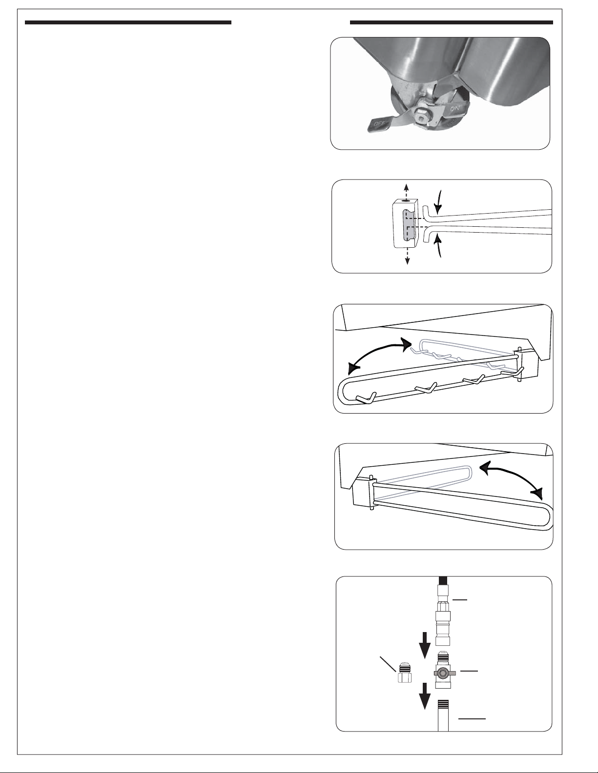
WHEELS AND CASTERS
To lock a caster press down on the side of the lever with the
word "ON" stamped on it until it stops and the caster will
not turn. To unlock, press down on the side stamped "OFF."
INSTALL THE TOOL HOLDER AND PAPERTOWEL
HOLDER
The rectangular mounting bracket for the tool holder and
the paper towel holder come pre-attached to the sides of
the cart.
Unpack the holder portion, squeeze the open ends together
slightly, and install them into the mounting bracket (see Fig.
18-2). Next, release the hanger so that the ends extend out
through the holes in the top and bottom of the mounting
bracket (Fig. 18-3, 18-4).
When not in use, the racks may be folded back against the
wall of the grill (Fig. 18-3, 18-4).
CONNECT THE GAS SUPPLY
For connecting a propane unit to a portable propane tank,
read the safety warnings and follow the instructions in the
section SAFE USE AND MAINTENANCE OF PROPANE
GAS CYLINDERS.
For household propane or natural gas units:
1. Turn OFF the gas supply at the source. The quick
disconnect hose is pre-installed on the valve manifold at
the manufacturer. Run the hose through the hole in the
bottom rear of the stand-alone unit, to the gas supply.
2. A shut-off valve is required within 6 feet of the unit.
If shut-off valve is connected to end of gas supply
stub:
• Connect the quick disconnect hose to the shut-off
valve (see Fig. 18-5). Tighten securely.
If shut-off valve is installed in-line:
• Install the supplied fl are adapter to the gas supply
using a pipe joint compound resistant to all gasses
(see Fig. 18-5). Tighten securely.
• Connect the quick disconnect hose to the fl are
adapter (see Fig. 18-5). Tighten securely.
3. Turn all burner valves to the OFF position. Turn the gas
supply on. Then carefully check all gas connections
for leaks with a brush and soapy water before lighting.
NEVER USE A MATCH OR OPEN FLAME TO TEST
FOR LEAKS.
INSTALLATION
INSTALLATION
Fig. 18-1 Lock/unlock wheels
Fig. 18-3 Tool holder detail
Fig. 18-4 Papertowel holder detail
Fig. 18-5 Connecting to a gas line
Gas supply
Flare adaptor
(use on gas
supply stub only
if shut-off valve
installed in-line)
Quick
disconnect hose
(coming from unit)
Shut-off valve
(required, not
included, must be
installed within 6
feet of the unit)
Fig. 18-2 Install tool holder / papertowel holder
Loading ...
Loading ...
Loading ...