Owner's Manual
CRRFrSMRH°
ELECT IC ASSIST KiT
MODEL NO. 486.245452
For Sleeve Hitch Models
486.24535, 486.24536, 486.24586 & 475 76 50=01
DO NOT RETURN TO STORE
For Missing Parts or Assembly
Questions Call 1-866-576-8388
CAUTION:
Before using this product, read
this manual and follow all Safety
Rules and Operating Instructions.
o
o
o
o
o
Safety
Assembly
Operation
Maintenance
Parts
Sears, Roebuck and Co., Hoffman Estates, IL 60179 U.S.A.
www.sears.com/craftsman
PRINTED IN U.S.A. FORM NO. 42551 (04/05/12)
SAFETY RULES .......................................................... 2
FULL SIZE HARDWARE CHART ................................ 3
CARTON CONTENTS ................................................. 4
ASSEMBLY .................................................................. 4
OPERATION ................................................................ 6
MAINTENANCE .......................................................... 6
REPAIR PARTS ILLUSTRATION ................................ 7
REPAIR PARTS LIST ................................................... 7
PARTS ORDERING/SERVICE ..................... Back Page
CRAFTSMAN ONE YEAR FULL WARRANTY
FOR ONE YEAR from the date of purchase, this product is warranted against any defects in material or workmanship. A
defective product will be replaced free of charge.
For warranty coverage details to obtain free replacement, visit the web site: www.craftsman.com
This warranty is void if this product is ever used while providing commercial services or if rented to another person.
This warranty gives you specific legal rights, and you may also have other rights which vary from state to state.
Sears Brands Management Corporation, Hoffman Estates, IL 60179
DO NOT RETURN TO STORE for Missing Parts or Assembly Questions
Call 1-866-576-8388 Attachment Hotline
Any power equipment can cause injury if operated improperly or ifthe user does not understand how to operate the equipment.
Exercise caution at all times, when using power equipment.
• Read this owners manual and your vehicle and
sleeve hitch owners manuals before using this
electric assist kit with the sleeve hitch.
Do not allow children to operate vehicle or sleeve
hitch.
Do not allow adults to operate the vehicle or sleeve
hitch without proper instructions.
Keep all nuts and bolts tight and be sure the
equipment is in safe operating condition.
Look for this symbol to point out important safety precautions. Itmeans--Attention!! Become
alert!! Your safety is involved.
The model number and serial numbers will be found on a
decal attached to the frame.
You should record both the serial number and the date of
purchase and keep in a safe place for future reference.
MODEL NUMBER:
SERIAL NUMBER:
DATE OF PURCHASE:
486.245452

_jA
B
D
C
/ E
\
\\\\
zF
KEY
A
B
C
D
QTY.
1
4
2
4
DESCRIPTION
Hex Bolt, 1/2" x 2-3/4"
Hex Bolt, 3/8" x 1"
Hex Lock Nut, 1/2"
Hex Nylock Nut, 3/8"
KEY
E
F
G
QTY.
5
1
1
DESCRIPTION
Flat Washer, 1/2"
Clevis Pin, 1/2" x 2"
Hair Cotter Pin, 3/32"
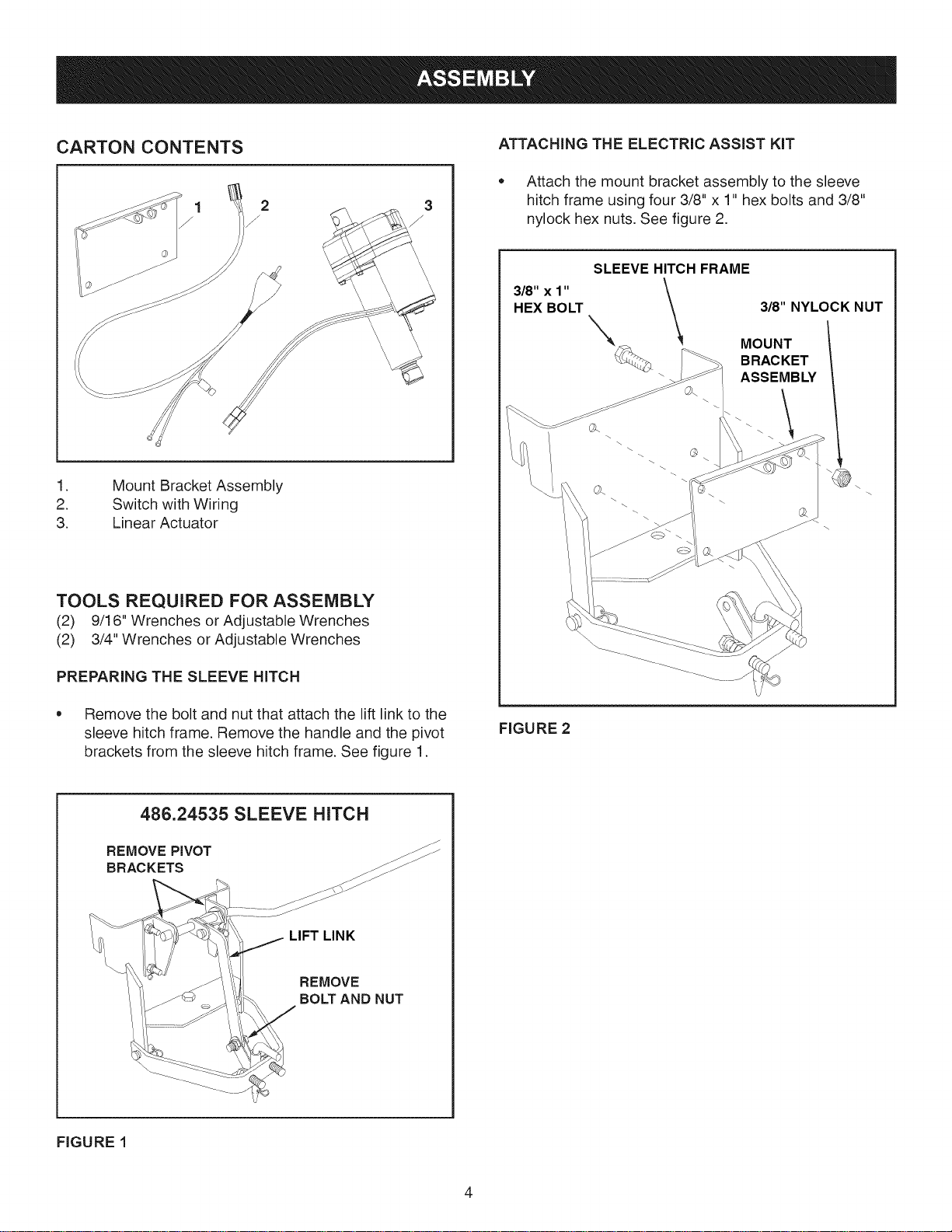
CARTON CONTENTS
.
2.
3.
Mount Bracket Assembly
Switch with Wiring
Linear Actuator
TOOLS REQUIRED FOR ASSEMBLY
(2) 9/16" Wrenches or Adjustable Wrenches
(2) 3/4" Wrenches or Adjustable Wrenches
PREPARING THE SLEEVE HITCH
• Remove the bolt and nut that attach the lift link to the
sleeve hitch frame. Remove the handle and the pivot
brackets from the sleeve hitch frame. See figure 1.
ATTACHING THE ELECTRIC ASSIST KIT
• Attach the mount bracket assembly to the sleeve
hitch frame using four 3/8" x 1" hex bolts and 3/8"
nylock hex nuts. See figure 2.
SLEEVE HITCH FRAME
\
318"x 1" \
\
HEX BOLT
3/8" NYLOCK NUT
MOUNT
BRACKET
ASSEMBLY
@\
FIGURE 2
486.24535 SLEEVE HITCH
REMOVE PIVOT
BRACKETS
LIFT LINK
REMOVE
BOLT AND NUT
FIGURE 1
4
• iMPORTANT: Connect to a 12 volt power source only.
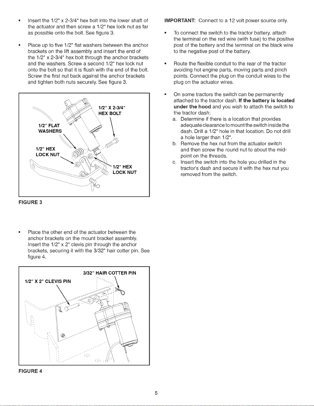
Insert the 1/2" x 2-3/4" hex bolt into the lower shaft of
the actuator and then screw a 1/2" hex lock nut as far
as possible onto the bolt. See figure 3.
Place up to five 1/2" flat washers between the anchor
brackets on the lift assembly and insert the end of
the 1/2" x 2-3/4" hex bolt through the anchor brackets
and the washers. Screw a second 1/2" hex lock nut
onto the bolt so that it is flush with the end of the bolt.
Screw the first nut back against the anchor brackets
and tighten both nuts securely. See figure 3.
1/2" FLAT
WASHERS
1/2" HEX
LOCK NUT
1/2" X 2-3/4"
HEX BOLT
\
HEX
LOCK NUT
To connect the switch to the tractor battery, attach
the terminal on the red wire (with fuse) to the positive
post of the battery and the terminal on the black wire
to the negative post of the battery.
Route the flexible conduit to the rear of the tractor
avoiding hot engine parts, moving parts and pinch
points. Connect the plug on the conduit wires to the
plug on the actuator wires.
On some tractors the switch can be permanently
attached to the tractor dash. If the battery is located
under the hood and you wish to attach the switch to
the tractor dash:
a. Determine if there is a location that provides
adequate clearance to mount the switch inside the
dash. Drill a 1/2" hole in that location. Do not drill
a hole larger than 1/2".
b. Remove the hex nut from the actuator switch
and then screw the round nut to about the mid-
point on the threads.
c. Insert the switch into the hole you drilled in the
tractor's dash and secure it with the hex nut you
removed from the switch.
FIGURE 3
Place the other end of the actuator between the
anchor brackets on the mount bracket assembly.
Insert the 1/2" x 2" clevis pin through the anchor
brackets, securing it with the 3/32" hair cotter pin. See
figure 4.
1/2" X 2" CLEVIS PIN
3/32" HAIR COTTER PIN
FIGURE 4

Keepclearofthelinearacutator,thesleevehitchand
theattachedimplementwhenraisingandlowering.
Thelinearactuatorisequippedwithasafetyclutch.
Whentheactuatorreachestheendofit'sstrokethe
clutchwillslipandmakealoudclickingsound.
• Cleanoffaftereachuse.
Storeinadrylocation.
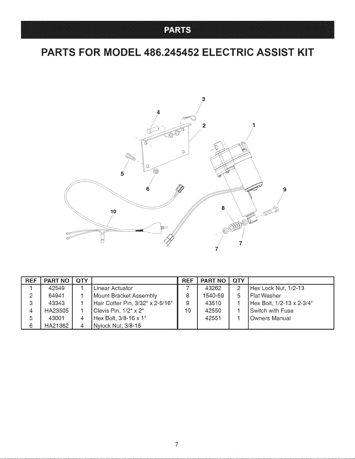
PARTS FOR MODEL 486.245452 ELECTRIC ASSIST KiT
4
3
/
2
/
1
/
/
REF
1
2
3
4
5
6
PART NO
42549
64941
43343
HA23505
43001
HA21362
QTY
1
1
1
1
4
4
REF
Linear Actuator 7
Mount Bracket Assembly 8
Hair Cotter Pin, 3/32" x 2-5/16" 9
Clevis Pin, 1/2" x 2" 10
Hex Bolt, 3/8-16 x 1"
PART NO QTY
43262 2 Hex Lock Nut, 1/2-13
1540-59 5 Flat Washer
43510 1 Hex Bolt, 1/2-13 x 2-3/4"
42550 1 Switch with Fuse
42551 1 Owners Manual
Ny!ock Nut, 3/8:1

To order replacement parts, call Sears Parts Direct 1-800-252-1698
or go to www.searspartsdirect.com


