
MULTI
F
MAX
MULTI
F
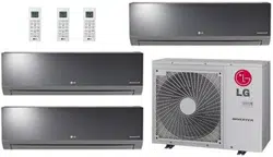
OUTDOOR UNIT
INSTALLATION MANUAL
Multi-Zone Heat Pump Systems
1.5 to 5 Tons
Dual and Tri-Zone
Multi F
Quad-Zone
Multi F
Eight-Zone
Multi F MAX

For continual product development, LG Electronics U.S.A., Inc. reserves the right to change specifications without notice.
© LG Electronics U.S.A., Inc.
PROPRIETARY DATA NOTICE
This document, as well as all reports, illustrations, data, information, and other materials are the property of
LG Electronics U.S.A., Inc., and are disclosed by LG Electronics U.S.A., Inc. only in confidence.
For more materials such as submittals, catalogs, engineering,
installation, owner’s, and service manuals, visit www.lghvac.com.
Do not throw away, destroy, or lose this manual.
Please read carefully and store in a safe place for future reference.
Content familiarity required for proper installation.
The instructions included in this manual must be followed to prevent product malfunction, property damage, injury, or death to the user or
other people. Incorrect operation due to ignoring any instructions will cause harm or damage. The level of seriousness is classified by the
symbols described by the summary list of safety precautions on page 4.
3
Safety Instructions
Due to our policy of continuous product innovation, some specifications may change without notification.
©LG Electronics U.S.A., Inc., Englewood Cliffs, NJ. All rights reserved. “LG” is a registered trademark of LG Corp.
MULTI
F
MAX
MULTI
F
SAFETY INSTRUCTIONS
TABLE OF SYMBOLS
This symbol indicates an imminently hazardous situation which, if not avoided, will result in death or serious injury.
This symbol indicates a potentially hazardous situation which, if not avoided, could result in death or serious injury.
This symbol indicates a potentially hazardous situation which, if not avoided, may result in minor or moderate injury.
This symbol indicates situations that may result in equipment or property damage accidents only.
This symbol indicates an action should not be completed.
DANGER
CAUTION
Do not install, remove, or re-install the unit by yourself
(end user). Ask the dealer or an trained technician to install
the unit.
,PSURSHULQVWDOODWLRQE\WKHXVHUPD\UHVXOWLQ¿UHH[SORVLRQHOHFWULF
shock, physical injury or death.
For replacement of an installed unit, always contact an LG
trained service provider.
7KHUHLVULVNRI¿UHHOHFWULFVKRFNH[SORVLRQDQGSK\VLFDOLQMXU\RU
death.
Wear protective gloves when handling equipment. Sharp
edges may cause personal injury.
Do not change the settings of the protection devices.
If the protection devices have been bypassed or is forced to operate
LPSURSHUO\RUSDUWVRWKHUWKDQWKRVHVSHFL¿HGE\/*DUHXVHGWKHUHLV
ULVNRI¿UHHOHFWULFVKRFNH[SORVLRQDQGSK\VLFDOLQMXU\RUGHDWK
Replace all control box and panel covers.
If cover panels are not installed securely, dust, water and animals may
HQWHUWKHRXWGRRUXQLWFDXVLQJ¿UHHOHFWULFVKRFNDQGSK\VLFDOLQMXU\RU
death.
Always check for system refrigerant leaks after the unit has
been installed or serviced.
([SRVXUHWRKLJKFRQFHQWUDWLRQOHYHOVRIUHIULJHUDQWJDVPD\OHDGWR
illness or death.
Periodically check that the outdoor frame is not damaged.
7KHUHLVDULVNRIH[SORVLRQSK\VLFDOLQMXU\RUGHDWK
If the air conditioner is installed in a small space, take
measures to prevent the refrigerant concentration from
exceeding safety limits in the event of a refrigerant leak.
Consult the latest edition of ASHRAE (American Society of Heating,
Refrigerating, and Air Conditioning Engineers) Standard 15. If the
UHIULJHUDQWOHDNVDQGVDIHW\OLPLWVDUHH[FHHGHGLWFRXOGUHVXOWLQSHUVRQ-
DOLQMXULHVRUGHDWKIURPR[\JHQGHSOHWLRQ
The branch distribution (BD) unit must be installed indoors;
do not install the BD unit in a highly humid environment.
There is risk of physical injury or death due to electric shock.
Dispose the packing materials safely.
• Packing materials, such as nails and other metal or wooden parts,
may cause puncture wounds or other injuries.
• Tear apart and throw away plastic packaging bags so that children
may not play with them and risk suffocation and death.
Install the unit considering the potential for strong winds or
earthquakes.
Improper installation may cause the unit to fall over, resulting in physical
injury or death.
Install the unit in a safe location where nobody can step, fall
onto it, or place objects on it.
Do not install the unit on a
defective stand.
It may result in an accident that causes physical injury or death.
Installation
'RQRWVWRUHRUXVHÀDPPDEOHJDVRUFRPEXVWLEOHVQHDU
the unit.
7KHUHLVULVNRI¿UHH[SORVLRQDQGSK\VLFDOLQMXU\RUGHDWK
Do not supply power to the unit until all wiring and pip-
ing are completed or reconnected and checked.
There is risk of physical injury or death due to electric shock.
DANGER
The instructions below must be followed to prevent product malfunction, property damage, injury or death to the user or other people. Incor-
rect operation due to ignoring any instructions will cause harm or damage. The level of seriousness is classified by the symbols described
below.
4
MULTI F / MULTI F MAX Outdoor Unit Installation Manual
Due to our policy of continuous product innovation, some specifications may change without notification.
©LG Electronics U.S.A., Inc., Englewood Cliffs, NJ. All rights reserved. “LG” is a registered trademark of LG Corp.
MULTI
F
MAX
MULTI
F
SAFETY INSTRUCTIONS
CAUTION
Installation, continued
Be very careful when transporting the product. There is a risk
of the product falling and causing physical injury.
• Use appropriate moving equipment to transport each frame; ensure
the equipment is capable of supporting the weights listed.
• Some products use polypropylene bands for packaging.
Do not
use polypropylene bands to lift the unit.
• Support the outdoor unit a minimum of four points to avoid slippage
from rigging apparatus.
/*(OHFWURQLFV86$,QFLVQRWUHVSRQVLEOHIRUDQ\SLSLQJFDOFXODWLRQV
refrigerant leaks, degradation of performance, or any other potential
problems or damages as a result of interconnecting piping, their joint
connections, isolation valves, introduced debris inside the piping system,
or other problems caused by the interconnecting piping system.
Do not install the product where it is exposed directly to
ocean winds.
Sea salt in the air may cause the product to corrode. Corrosion,
SDUWLFXODUO\RQWKHFRQGHQVHUDQGHYDSRUDWRU¿QVFRXOGFDXVHSURGXFW
PDOIXQFWLRQRULQHI¿FLHQWRSHUDWLRQ
When installing the outdoor unit in a low-lying area, or a lo-
cation that is not level, use a raised concrete pad or concrete
blocks to provide a solid, level foundation.
This prevents water damage and abnormal vibration.
Properly insulate all cold surfaces to prevent “sweating.”
Cold surfaces such as uninsulated piping can generate condensate that
may drip and cause water damage to walls.
Always check for system refrigerant leaks after the unit has
been installed or serviced.
/RZUHIULJHUDQWOHYHOVPD\FDXVHSURGXFWIDLOXUH
The branch distribution (BD) unit must be installed indoors;
Do not install the BD box in a highly humid environment.
There is risk of product failure and property damage.
Do not make refrigerant substitutions. Use R410A only.
,IDGLIIHUHQWUHIULJHUDQWLVXVHGRUDLUPL[HVZLWKRULJLQDOUHIULJHUDQWWKH
unit will malfunction and be damaged.
'RQRWVWRUHRUXVHÀDPPDEOHJDVFRPEXVWLEOHVQHDUWKH
unit.
There is a risk of product failure.
Do not use the product for mission critical or special pur-
pose applications such as preserving foods, works of art, or
other precision air conditioning applications. The equipment
is designed to provide comfort cooling and heating.
There is risk of property damage.
Keep the unit upright during installation to avoid vibration or
water leakage.
When connecting refrigerant tubing, remember to allow for
pipe expansion.
Improper piping may cause refrigerant leaks and system malfunction.
Do not install the outdoor unit or BD unit in a noise-sen-
sitive area.
Take appropriate actions at the end of HVAC equipment life
to recover, recycle, reclaim or destroy R410A refrigerant
according to applicable U.S. Environmental Protection
Agency (EPA) rules.
Periodically check that the outdoor frame is not damaged.
There is a risk of equipment damage.
Install the unit in a safe location where nobody can step on
or fall onto it. Do not install the unit on a defective stand.
There is a risk of unit and property damage.
Install the drain hose to ensure adequate drainage.
There is a risk of water leakage and property damage.
Properly insulate all cold surfaces to prevent “sweating.”
Cold surfaces such as uninsulated piping can generate condensate
that could drip, causing a slippery surface that creates a risk of slipping,
falling, and personal injury.
5
Safety Instructions
Due to our policy of continuous product innovation, some specifications may change without notification.
©LG Electronics U.S.A., Inc., Englewood Cliffs, NJ. All rights reserved. “LG” is a registered trademark of LG Corp.
MULTI
F
MAX
MULTI
F
SAFETY INSTRUCTIONS
Do not supply power to the unit until all electrical wiring,
controls wiring, piping, installation, and refrigerant system
evacuation are completed.
System may malfunction.
The information contained in this manual is intended for use
E\DQLQGXVWU\TXDOL¿HGH[SHULHQFHGFHUWL¿HGHOHFWULFLDQ
familiar with the U.S. National Electric Code (NEC) who is
equipped with the proper tools and test instruments.
Failure to carefully read and follow all instructions in this manual can
result in equipment malfunction, property damage, personal injury or
death.
All electric work must be performed by a licensed electrician
and conform to local building codes or, in the absence of
local codes, with the National Electrical Code, and the
instructions given in this manual.
If the power source capacity is inadequate or the electric work is not
SHUIRUPHGSURSHUO\LWPD\UHVXOWLQ¿UHHOHFWULFVKRFNSK\VLFDOLQMXU\RU
death.
Refer to local, state, and federal codes, and use power wires
RIVXI¿FLHQWFXUUHQWFDSDFLW\DQGUDWLQJ
:LUHVWKDWDUHWRRVPDOOPD\JHQHUDWHKHDWDQGFDXVHD¿UH
6HFXUHDOO¿HOGZLULQJFRQQHFWLRQVZLWKDSSURSULDWHZLUH
strain relief.
Improperly securing wires will create undue stress on equipment power
OXJV,QDGHTXDWHFRQQHFWLRQVPD\JHQHUDWHKHDWFDXVHD¿UHDQG
physical injury or death.
Ensure the system is connected to a dedicated power source
that provides adequate power.
If the power source capacity is inadequate or the electric work is not per-
IRUPHGSURSHUO\LWPD\UHVXOWLQ¿UHHOHFWULFVKRFNSK\VLFDOLQMXU\RUGHDWK
Properly tighten all power connections.
/RRVHZLULQJPD\RYHUKHDWDWFRQQHFWLRQSRLQWVFDXVLQJD¿UHSK\VLFDO
injury or death.
Do not change the settings of the protection devices.
If the protection devices have been bypassed or are forced to operate
LPSURSHUO\RUSDUWVRWKHUWKDQWKRVHVSHFL¿HGE\/*DUHXVHGWKHUHLV
ULVNRI¿UHHOHFWULFVKRFNH[SORVLRQDQGSK\VLFDOLQMXU\RUGHDWK
Wiring
DANGER
High voltage electricity is required to operate this system.
Adhere to the NEC code and these instructions when wiring.
Improper connections and inadequate grounding can cause accidental
injury or death.
Always ground the unit following local, state, and NEC codes.
7KHUHLVULVNRI¿UHHOHFWULFVKRFNDQGSK\VLFDOLQMXU\RUGHDWK
Turn the power off at the nearest disconnect before servicing
the equipment.
Electrical shock can cause physical injury or death.
Properly size all circuit breakers or fuses.
7KHUHLVULVNRI¿UHHOHFWULFVKRFNH[SORVLRQSK\VLFDOLQMXU\RUGHDWK
Do not share the electrical circuit with other appliances.
7KHUHLVULVNRI¿UHHOHFWULFVKRFNDQGSK\VLFDOLQMXU\RUGHDWKGXHWR
heat generation.
Do not use damaged or loose power wiring. Do not
modify or extend the outdoor unit’s power wiring randomly.
Ensure that the power wiring will not be pulled nor weight be
placed on the power wiring during operation.
7KHUHLVULVNRI¿UHHOHFWULFVKRFNDQGSK\VLFDOLQMXU\RUGHDWK
6
MULTI F / MULTI F MAX Outdoor Unit Installation Manual
Due to our policy of continuous product innovation, some specifications may change without notification.
©LG Electronics U.S.A., Inc., Englewood Cliffs, NJ. All rights reserved. “LG” is a registered trademark of LG Corp.
MULTI
F
MAX
MULTI
F
Do not allow water, dirt, or animals to enter the unit.
7KHUHLVULVNRI¿UHHOHFWULFVKRFNSK\VLFDOLQMXU\RUGHDWK
Do not operate the unit with the panel(s) or protective
FRYHUVUHPRYHGNHHS¿QJHUVDQGFORWKLQJDZD\IURP
moving parts.
The rotating, hot, cold, and high-voltage parts of the unit can cause
physical injury or death.
Do not touch the refrigerant piping during or after
operation.
It can cause burns or frostbite.
Do not open the inlet during operation.
There is risk of electric shock, physical injury or death.
Operation
DANGER
'RQRWSURYLGHSRZHUWRRURSHUDWHWKHXQLWLILWLVÀRRGHG
or submerged.
7KHUHLVULVNRI¿UHHOHFWULFVKRFNSK\VLFDOLQMXU\RUGHDWK
Use a dedicated breaker for this product.
7KHUHLVULVNRI¿UHHOHFWULFVKRFNSK\VLFDOLQMXU\RUGHDWK
Do not operate the disconnect switch with wet hands.
7KHUHLVULVNRI¿UHHOHFWULFVKRFNSK\VLFDOLQMXU\RUGHDWK
Periodically verify the equipment mounts have not
deteriorated.
If the base collapses, the unit could fall and cause physical injury or
death.
Use inert (nitrogen) gas when performing leak tests or air
purges.
'RQRWXVHFRPSUHVVHGDLUR[\JHQRUÀDPPD-
ble gases.
8VLQJWKHVHVXEVWDQFHVPD\FDXVH¿UHH[SORVLRQDQGSK\VLFDOLQMXU\
or death.
If refrigerant leaks out, ventilate the area before operating the
unit.
If the unit is mounted in an enclosed, low-lying, or poorly ventilated area,
DQGWKHV\VWHPGHYHORSVDUHIULJHUDQWOHDNLWPD\FDXVHD¿UHHOHFWULF
VKRFNH[SORVLRQSK\VLFDOLQMXU\RUGHDWK
To avoid physical injury, use caution when cleaning or
servicing the air conditioner.
CAUTION
&OHDQXSWKHVLWHDIWHUVHUYLFLQJLV¿QLVKHGDQGFKHFNWKDW
no metal scraps, screws, or bits of wiring have been left
inside or surrounding the unit.
Do not use the product for mission critical or special pur-
pose applications such as preserving foods, works of art, or
other precision air conditioning applications. The equipment
is designed to provide comfort cooling and heating.
2LOVWHDPVXOIXULFVPRNHHWFFDQVLJQL¿FDQWO\UHGXFHWKHSHUIRUPDQFH
of the unit, or damage its parts.
Do not block the inlet or outlet.
Unit may malfunction.
Do not allow water, dirt, or animals to enter the unit.
There is risk of unit failure.
Do not open the inlet during operation.
There is risk of unit failure.
Do not operate the unit when the panel(s) or protective
FRYHUVDUHUHPRYHGNHHS¿QJHUVDQGFORWKLQJDZD\IURP
moving parts.
Non-secured covers can result in malfunction due to dust or water in the
service panel.
Periodically verify the equipment mounts have not
deteriorated.
If the base collapses, the unit could fall and cause property damage or
product failure.
Use a only soft cloth to clean the air conditioner. Do not
use wax, thinner, or strong detergents.
Strong cleaning products may damage the surface of the air conditioner,
or may cause its appearance to deteriorate.
SAFETY INSTRUCTIONS

7
Product Data
Due to our policy of continuous product innovation, some specifications may change without notification.
©LG Electronics U.S.A., Inc., Englewood Cliffs, NJ. All rights reserved. “LG” is a registered trademark of LG Corp.
MULTI
F
MAX
MULTI
F
TABLE OF CONTENTS
Safety Instructions ......................................................................................................................................................................................................3-6
0XOWL)0XOWL)0$;2XWGRRU8QLW6SHFLÀFDWLRQV .................................................................................................................................................8-10
Electrical Data ................................................................................................................................................................................................................11
R410A Refrigerant ........................................................................................................................................................................................................ 12
General Installation Guidelines ..............................................................................................................................................................................13-34
/RFDWLRQ6HOHFWLRQIRU2XWGRRU8QLWV ..........................................................................................................................................................................13
Oceanside Installation Precautions ............................................................................................................................................................................13
Rooftop Installations ...................................................................................................................................................................................................14
Planning for Snow and Ice ..........................................................................................................................................................................................14
7LH'RZQVDQG/LJKWQLQJ3URWHFWLRQ ........................................................................................................................................................................... 14
Allowable Clearances ............................................................................................................................................................................................15-17
5LJJLQJDQG/LIWLQJ,QVWUXFWLRQV ..................................................................................................................................................................................18
Platform Instructions ...................................................................................................................................................................................................19
0RXQWLQJ%ROW/RFDWLRQ ...............................................................................................................................................................................................19
/RFDWLRQ6HOHFWLRQIRU%UDQFK'LVWULEXWLRQ8QLW .....................................................................................................................................................20-21
Branch Distribution Unit Installation .......................................................................................................................................................................22-23
Piping Preparation ...................................................................................................................................................................................................24-25
Piping Materials and Handling ...............................................................................................................................................................................26-34
Refrigerant Piping Connections .............................................................................................................................................................................35-40
Flushing the Refrigerant Piping .................................................................................................................................................................................. 41
Leak Test and Vacuum Procedures .......................................................................................................................................................................42-44
Refrigerant Charge ..................................................................................................................................................................................................45-47
Refrigerant Piping Insulation .................................................................................................................................................................................48-52
Electrical Wiring ......................................................................................................................................................................................................53-70
*HQHUDO,QIRUPDWLRQ ...............................................................................................................................................................................................53-54
Power Wiring and Communications Cable Connections .......................................................................................................................................55-59
Test Run .....................................................................................................................................................................................................................60
DIP Switch Settings ...............................................................................................................................................................................................61-65
Self Diagnosis Functions .......................................................................................................................................................................................66-71
Caution for Refrigerant Leakage ............................................................................................................................................................................72-73
Installation Checklists .............................................................................................................................................................................................74-79
8
MULTI F / MULTI F MAX Outdoor Unit Installation Manual
Due to our policy of continuous product innovation, some specifications may change without notification.
©LG Electronics U.S.A., Inc., Englewood Cliffs, NJ. All rights reserved. “LG” is a registered trademark of LG Corp.
MULTI
F
MAX
MULTI
F
SPECIFICATIONS
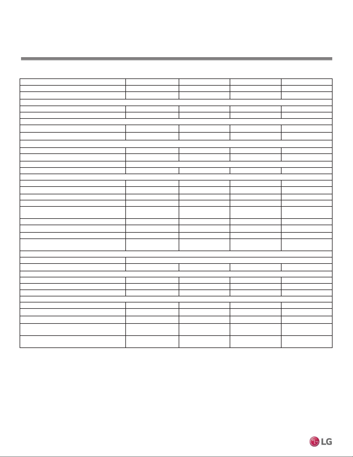
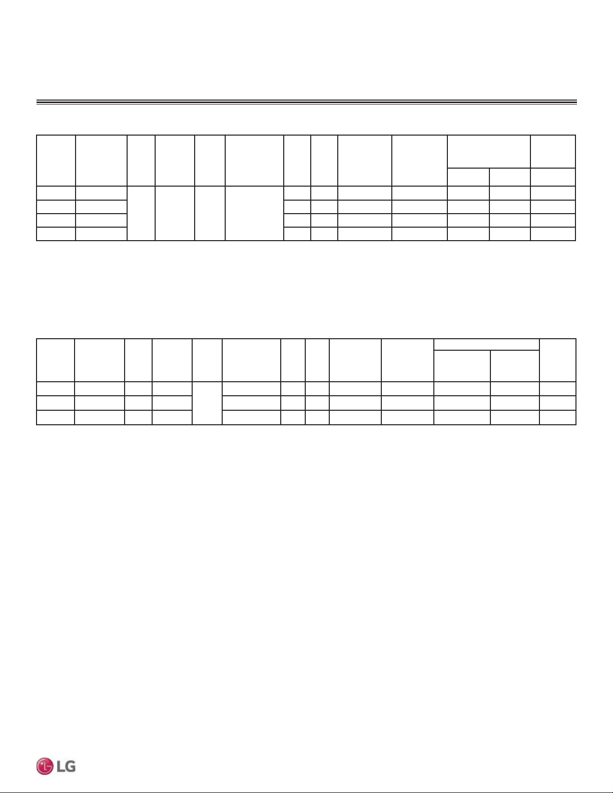
Model Number LMU18CHV LMU24CHV LMU30CHV LMU36CHV
Cooling Capacity (Btu/h)
1
(Min.~Rated~ Max.) 8,400~17,000~19,000 8,400~20,000~25,000 8,400~30,000~36,000 8,400~32,000~38,400
Heating Capacity (Btu/h)
1
(Min.~Rated~ Max.) 10,248~22,000~24,000 9,240~24,000~28,800 9,240~32,000~38,400 9,240~36,000~41,600
Operating Range
Cooling (°F DB) 14
7
- 118 14
7
- 118 14
7
- 118 14
7
- 118
Heating (°F WB) -4 - 64 -4 - 64 -4 - 64 -4 - 64
Compressor
Inverter Quantity Twin Rotary x 1 Twin Rotary x 1 Twin Rotary x 1 Twin Rotary x 1
Oil Type FVC68D FVC68D FVC68D FVC68D
Fan (Side Discharge)
Type Propeller Propeller Propeller Propeller
Motor Output (W) x Qty. 85.4 x 1 85.4 x 1 124.2 x 1 124.2 x 1
Motor/Drive Brushless Digitally Controlled / Direct
Maximum Air Volume (CFM) 1,766 1,766 2,119 2,119
Unit Data
Refrigerant Type R410A R410A R410A R410A
Refrigerant Control/Location EEV/Outdoor Unit EEV/Outdoor Unit EEV/Outdoor Unit EEV/Outdoor Unit
Min. Number Indoor Units/System
2
2222
Max. Number Indoor Units/System
2
2344
Maximum Allowable Total Indoor Unit
Connected Capacity (Btu/h)
24,000 33,000 40,000 48,000
Sound Pressure (Cooling / Heating) dB(A)
3
49 / 52 49 / 52 52 / 55 52 / 55
Net Unit Weight (lbs.) 100 100 137 137
Shipping Weight (lbs.) 108 108 148 148
Power Wiring / Communications Cable
(No. x AWG)
4,5
4C x 18 4C x 18 4C x 18 4C x 18
Heat Exchanger
Material and Fin Coating Copper Tube/Aluminum Fin and GoldFin™/Hydrophilic
Rows/Columns/Fins per inch x Qty. (2 x 28 x 14) x 1 (2 x 28 x 14) x 1 (2 x 38 x 14) x 1 (2 x 38 x 14) x 1
Piping
Liquid Line Connection (in., OD) x Qty. 1/4 x 2 1/4 x 3 1/4 x 4 1/4 x 4
Vapor Line Connection (in., OD) x Qty. 3/8 x 2 3/8 x 3 3/8 x 4 3/8 x 4
Factory Charge lbs. of R410A 3.96 3.96 6.18 6.18
Piping Lengths
Maximum Total Piping (ft.)
6
164.0 246.1 246.1 246.1
Maximum Outdoor Unit to Indoor Unit Piping (ft) 82.0 82.0 82.0 82.0
Piping Length (No Additional Refrigerant [ft]) 49.2 73.8 98.4 98.4
Maximum Elevation between Outdoor Unit
and Indoor Unit (ft.)
49.2 49.2 49.2 49.2
Maximum Elevation between Indoor Unit and
Indoor Unit (ft.)
24.6 24.6 24.6 24.6
Table 1: 0XOWL)2XWGRRU8QLW6SHFL¿FDWLRQV
1
Rated capacity applied with non-ducted indoor units, and is rated 0 ft. above sea level
with 25 ft. of refrigerant line per indoor unit and a 0 ft. level difference between outdoor and
indoor units. All capacities are net with a combination ratio between 95 – 105%.
Rated cooling capacity obtained with air entering the indoor unit at 80ºF dry bulb (DB) and
67ºF wet bulb (WB) and outdoor ambient conditions of 95ºF dry bulb (DB) and 75ºF wet
bulb (WB).
Rated heating capacity obtained with air entering the indoor unit at 70ºF dry bulb (DB) and
60ºF wet bulb (WB) and outdoor ambient conditions of 47ºF dry bulb (DB) and 43ºF wet
bulb (WB).
2
At least two indoor units should be connected. For allocated capacity information, see
the combination tables in the "Multi F / Multi F MAX Combination Data Manual" on www.
lg-dfs.com. For performance data, see "Multi F / Multi F MAX Performance Data Manual"
on www.lg-dfs.com.
3
Sound pressure levels are tested in an anechoic chamber under ISO Standard 3745 and
are the same in both cooling and heating mode. These values can increase due to ambient
conditions during operation.
4
3RZHUZLULQJWRWKHRXWGRRUXQLWLV¿HOGVXSSOLHGVROLGRUVWUDQGHGDQGPXVWFRPSO\ZLWK
the applicable local and national codes. For detailed information, please refer to electrical
characteristics on page 11.
5
All power wiring / communication cable to be minimum 18 AWG from the outdoor unit to
the indoor unit, stranded, shielded or unshielded (if shielded, it must be grounded to the
chassis of the outdoor unit only), and must comply with applicable local and national codes.
For detailed electrical information, please refer to electric characteristics on page 11.
6
Piping lengths are equivalent.
7
,QVWDOODWLRQRIDQRSWLRQDO/RZ$PELHQW:LQG%DIÀH.LWZLOODOORZRSHUDWLRQGRZQWR)LQ
cooling mode.
Multi F Outdoor Units
9
Product Data
Due to our policy of continuous product innovation, some specifications may change without notification.
©LG Electronics U.S.A., Inc., Englewood Cliffs, NJ. All rights reserved. “LG” is a registered trademark of LG Corp.
MULTI
F
MAX
MULTI
F
SPECIFICATIONS
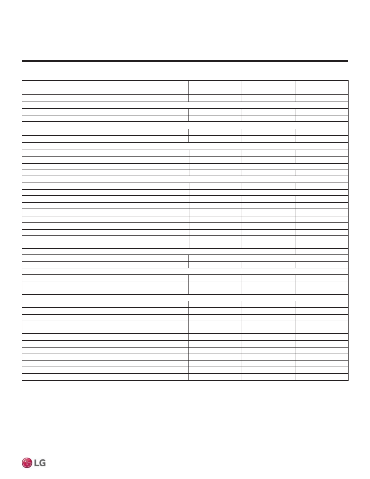
Multi F MAX Outdoor Units
Table 2: Multi F MAX Outdoor Unit General Data.
Model Number LMU480HV LMU540HV LMU600HV
Cooling Capacity (Btu/h) (Minimum ~ Rated ~ Maximum)
1
14,400~48,000~58,000 14,400~52,500~63,200 15,600~60,000~68,000
Heating Capacity (Btu/h)
(Minimum ~ Rated ~ Maximum)
1
15,840~54,000~61,000 16,272~58,000~64,000 17,940~64,000~70,000
Operating Range
Cooling (°F DB) 14
7
- 118 14
7
- 118 14
7
- 118
Heating (°F WB) -4 - 64 -4 - 64 -4 - 64
Compressor
Inverter Quantity Twin Rotary x 1 Twin Rotary x 1 Twin Rotary x 1
Oil Type FVC68D FVC68D FVC68D
Fan (Side Discharge)
Type Propeller Propeller Propeller
Motor Output (W) x Qty. 124.2 x 2 124.2 x 2 124.2 x 2
Motor/Drive Brushless Digitally Controlled/Direct
Maximum Air Volume (CFM) 2,119 x 2 2,119 x 2 2,119 x 2
Unit Data
Refrigerant Type R410A R410A R410A
Refrigerant Control/Location EEV / Outdoor Unit, Branch Distribution Unit
Min. Number Indoor Units/System
2
222
Max. Number Indoor Units/System
2
888
Maximum Allowable Total Indoor Unit Connected Capacity (Btu/h) 65,000 73,000 81,000
Sound Pressure ±3 dB(A)
3
(Cooling / Heating) 54 / 56 54 / 56 56 / 58
Net Unit Weight (lbs.) 214 214 223
Shipping Weight (lbs.) 236 236 249
Power/Communications Wiring Between ODU and BD Unit
(No. X AWG)
4,5
4C X 16 4C X 16 4C x 16
Heat Exchanger
Material and Fin Coating Copper Tube / Aluminum Fin and GoldFin™/Hydrophilic
Rows/Columns/Fins per inch x Qty. (2 x 32 x 14) x 2 (2 x 32 x 14) x 2 (3 x 32 x 14) x 2
Piping
Liquid Line Connection (in., OD) x Qty. 3/8 x 1 3/8 x 1 3/8 x 1
Vapor Line Connection (in., OD) x Qty. 3/4 x 1 3/4 x 1 3/4 x 1
Factory Charge lbs. of R410A 9.7 9.7 12.3
Piping Lengths
Maximum Total System Piping (ft.)
6
475.7 475.7 475.7
Maximum Main Pipe Length (Outdoor Unit to BD Unit [ft.]) 180.4 180.4 180.4
Total Branch Piping (BD Units to all Indoor Units [ft.]) 295.3 295.3 295.3
Maximum Branch Pipe Length (Length between each
BDU and IDU [ft.])
49.2 49.2 49.2
Maximum Outdoor Unit to Indoor Unit Pipe Length (ft.) 229.6 229.6 229.6
Max. Main Piping Length (No Additional Refrigerant (ft.) 16 16 16
Max. Branch Piping Length (No Additional Refrigerant (ft.) 131 131 147.6
Maximum Elevation between Outdoor Unit and Indoor Unit (ft.) 98.4 98.4 98.4
Maximum Elevation between Indoor Unit and Indoor Unit (ft.) 49.2 49.2 49.2
Maximum Elevation between BD Unit and Indoor Unit (ft.) 32.8 32.8 32.8
Maximum Elevation between BD Unit and BD Unit (ft.) 49.2 49.2 49.2
1
Rated capacity applied with non-ducted indoor units, and is rated 0 ft. above sea level with a 0
ft. level difference between outdoor and indoor units. All capacities are net with a combination
ratio between 95 – 105%.
Rated cooling capacity obtained with air entering the indoor unit at 80ºF dry bulb (DB) and 67ºF
wet bulb (WB) and outdoor ambient conditions of 95ºF dry bulb (DB) and 75ºF wet bulb (WB).
Rated heating capacity obtained with air entering the indoor unit at 70ºF dry bulb (DB) and 60ºF
wet bulb (WB) and outdoor ambient conditions of 47ºF dry bulb (DB) and 43ºF wet bulb (WB).
2
At least one Branch Distribution Unit is required for system operation; a maximum of two can
be installed per outdoor unit with use of Y-branch accessory (PMBL5620). At least two indoor
units should be connected. For allocated capacity information, see the combination tables in
the “Multi F / Multi F MAX Combination Data Manual” on www.lg-dfs.com. For performance
data, see “Multi F / Multi F MAX Performance Data Manual” on www.lg-dfs.com.
3
Sound pressure levels are tested in an anechoic chamber under ISO Standard 3745.
These values can increase due to ambient conditions during operation.
4
3RZHUZLULQJWRWKHRXWGRRUXQLWLV¿HOGVXSSOLHGVROLGRUVWUDQGHGDQGPXVWFRPSO\ZLWK
the applicable local and national codes. For detailed information, please refer to electrical
characteristics on page 11.
5
All power wiring / communication cable to be minimum 16 AWG from the outdoor unit to
the BD unit (Multi F MAX systems only), and 18 AWG from the BD unit to the indoor unit,
stranded, shielded or unshielded (if shielded, it must be grounded to the chassis of the
outdoor unit only), and must comply with applicable local and national codes. For detailed
electrical information, please refer to electric characteristics on page 11.
6
Piping lengths are equivalent.
7
,QVWDOODWLRQRIDQRSWLRQDO/RZ$PELHQW:LQG%DIÀH.LWZLOODOORZRSHUDWLRQGRZQWR)LQ
cooling mode.
10
MULTI F / MULTI F MAX Outdoor Unit Installation Manual
Due to our policy of continuous product innovation, some specifications may change without notification.
©LG Electronics U.S.A., Inc., Englewood Cliffs, NJ. All rights reserved. “LG” is a registered trademark of LG Corp.
MULTI
F
MAX
MULTI
F
SPECIFICATIONS
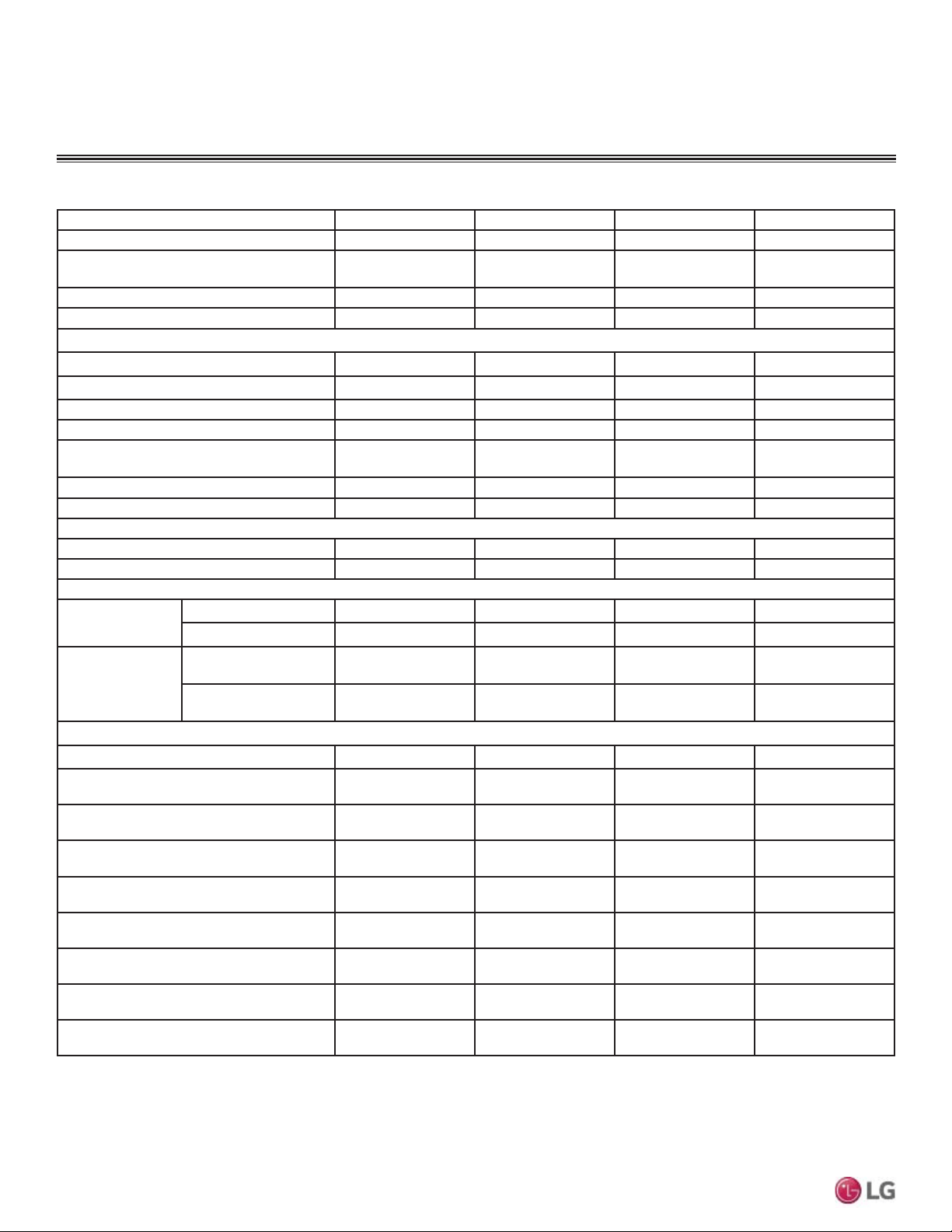
Multi F MAX Branch Distribution Units
Table 3: Multi F MAX BD Unit General Data.
Model Number PMBD3620 PMBD3630 PMBD3640 PMBD3641
No. of Connectible Indoor Units
1
1-2 1-3 1-4 1-4
Max. Nominal Capacity / Port (Btu/h)
2
24,000 24,000 24,000
24,000 for A,B,C Ports;
36,000 for D Port
Max. Nominal Capacity / BD Unit (Btu/h) 48,000 72,000 73,000 73,000
Operation Temperature Range (°F DB) 0 ~ 150 0 ~ 150 0 ~ 150 0 ~ 150
Unit Data
Refrigerant Type R410A R410A R410A R410A
Power Supply V, Ø, Hz 208-230, 1, 60 208-230, 1, 60 208-230, 1, 60 208-230, 1, 60
Power Input (W) 16 24 32 32
Rated Amps (A) 0.08 0.12 0.16 0.16
Dimensions W x H x D (in.)
17-3/32 x 6-13/32
x 10-23/32
17-3/32 x 6-13/32
x 10-23/32
17-3/32 x 6-13/32
x 10-23/32
17-3/32 x 6-13/32
x 10-23/32
Net Unit Weight (lbs.) 13 14.3 15.7 15.7
Shipping Weight (lbs.) 15 17 18 18
Power Wiring / Communication Cables
3
From Outdoor Unit to BD Unit (Qty. x AWG)
3
4 x 16 4 x 16 4 x 16 4 x 16
From BD Unit to Indoor Unit (Qty. x AWG)
3
4 x 18 4 x 18 4 x 18 4 x 18
Piping Connections
Outdoor Unit to
BD Unit
Liquid (in., OD) Ø3/8 Ø3/8 Ø3/8 Ø3/8
Vapor (in., OD) Ø3/4 Ø3/4 Ø3/4 Ø3/4
BD Unit to
Indoor Units
Liquid (in., OD) x Qty. Ø1/4 x 2 Ø1/4 x 3 Ø1/4 x 4
Ø1/4 x 3
Ø3/8 x 1
Vapor (in., OD) x Qty. Ø3/8 x 2 Ø3/8 x 3 Ø3/8 x 4
Ø3/8 x 3
Ø5/8 x 1
Piping Lengths
Maximum Total System Piping (ft.)
4
475.7 475.7 475.7 475.7
Maximum Main Pipe Length (Outdoor Unit
to BD Units [ft.])
180.4 180.4 180.4 180.4
Maximum Total Branch Piping (BD Units to
Indoor Units [ft.])
295.3 295.3 295.3 295.3
Maximum Branch Pipe Length Between
BD Unit and Each Indoor Unit [ft.])
49.2 49.2 49.2 49.2
Maximum Outdoor Unit to Indoor Unit
Pipe Length (ft.)
229.6 229.6 229.6 229.6
Main Piping Length (No Additional
Refrigerant (ft.)
16 16 16 16
Branch Piping Length (No Additional
Refrigerant (ft.)
131 131 131 131
Maximum Elevation between BD Unit and
Indoor Unit (ft.)
32.8 32.8 32.8 32.8
Maximum Elevation between BD Unit and
BD Unit (ft.)
49.2 49.2 49.2 49.2
1
At least one Branch Distribution Unit is required for system operation; a maximum of two can be installed per outdoor unit with use of Y-branch accessory (PMBL5620) To connect only
one (1) indoor unit to a branch distribution unit, the system must include another branch distribution unit with at least one (1) connected indoor unit.
2
Branch Distribution Unit can accommodate from one (1) indoor unit up to four (4) indoor units depending on the ports available on the Branch Distribution Unit.
3
All power wiring / communication cable to be minimum 16 AWG from the outdoor unit to the BD unit (Multi F MAX systems only), and 18 AWG from the BD unit to the indoor unit,
stranded, shielded or unshielded (if shielded, it must be grounded to the chassis of the outdoor unit only), and must comply with applicable local and national codes. For detailed electrical
information, please refer to electric characteristics on page 11.
4
Piping lengths are equivalent.
11
Product Data
Due to our policy of continuous product innovation, some specifications may change without notification.
©LG Electronics U.S.A., Inc., Englewood Cliffs, NJ. All rights reserved. “LG” is a registered trademark of LG Corp.
MULTI
F
MAX
MULTI
F
ELECTRICAL DATA
Nominal
Tons
Unit Model
No.
Hertz Voltage Phase
Voltage
Range
(Min. to Max.)
MCA MOP
Compressor
Quantity
Compressor
Motor RLA
Outdoor Fan Motor
Indoor
Fan
Motor
kW FLA FLA
1.5 LMU18CHV
60 208 - 230 1 187 - 253
13.3 20 1 8.9 0.09 0.59 1.60
2 LMU24CHV 14.3 20 1 9.4 0.09 0.59 2.00
2.5 LMU30CHV 16.6 25 1 10.8 0.12 0.73 2.40
3 LMU36CHV 17.9 25 1 11.2 0.12 0.73 3.20
Voltage tolerance is ±10%.
Maximum allowable voltage unbalance is 2%.
RLA = Rated Load Amps.
MCA = Minimum Circuit Ampacity.
Maximum Overcurrent Protection (MOP) is calculated as
follows: (Largest motor FLA x 2.25) + (Sum of other motor
FLA) rounded down to the nearest standard fuse size.
Indoor Fan Motor (FLA) is based on the maximum combina-
tion of indoor units.
The max combination for each outdoor unit is:
- 18,000 ODU (LMU18CHV): 12,000 IDU x 2
- 24,000 ODU (LMU24CHV): 12,000 IDU x 2 + 9,000 IDU
x 1
- 30,000 ODU (LMU30CHV): 12,000 IDU x 3
- 36,000 ODU (LMU36CHV): 12,000 IDU x 4
Table 4: Multi F Outdoor Unit Electrical Data.
Nominal
Tons
Unit Model
No.
Hertz Voltage Phase
Voltage
Range
(Min. to Max.)
MCA MOP
Compressor
Quantity
Compressor
Motor RLA
Condenser Fan Motor(s)
Indoor
Fan
Motor
Condenser
Fan Quantity
x kW
Condenser
Fan Motor
FLA
4.0 LMU480HV 60 208 - 230
1
187 - 253 27.3 40 1 17.5 2 x 0.12 0.73 x 2 4.0
4.5 LMU540HV 60 208 - 230 187 - 253 29.4 40 1 18.5 2 x 0.12 0.73 x 2 4.8
5.0 LMU600HV 60 208 - 230 187 - 253 32.2 45 1 20.4 2 x 0.12 0.73 x 2 5.2
Voltage tolerance is ±10%.
Maximum allowable voltage unbalance is 2%.
RLA = Rated Load Amps.
MCA = Minimum Circuit Ampacity.
Maximum Overcurrent Protection (MOP) is calculated as
follows: (Largest motor FLA x 2.25) + (Sum of other motor
FLA) rounded down to the nearest standard fuse size.
Indoor Fan Motor (FLA) is based on the maximum combina-
tion of indoor units.
The max combination for each outdoor unit is:
- 48,000 ODU (LMU480HV): 12,000 IDU x 5
- 54,000 ODU (LMU540HV): 12,000 IDU x 6
- 60,000 ODU (LMU6000HV): 12,000 IDU x 6 + 9,000 IDU
x 1
Table 5: Multi F MAX Electrical Data.
Multi F and Multi F MAX Outdoor Units
12
MULTI F / MULTI F MAX Outdoor Unit Installation Manual
Due to our policy of continuous product innovation, some specifications may change without notification.
©LG Electronics U.S.A., Inc., Englewood Cliffs, NJ. All rights reserved. “LG” is a registered trademark of LG Corp.
MULTI
F
MAX
MULTI
F
R410A Refrigerant
R410A refrigerant has a higher operating pressure in comparison to R22 refrigerant and, therefore, all piping system materials installed must
have a higher resisting pressure than the materials traditionally used in R22 systems.
R410A refrigerant is an azeotrope of R32 and R125, mixed at 50:50, so the ozone depletion potential (ODP) is 0.
WARNING
'RQRWSODFHUHIULJHUDQWF\OLQGHULQGLUHFWVXQOLJKW5HIULJHUDQWF\OLQGHUPD\H[SORGHFDXVLQJVHYHUHLQMXU\RUGHDWK
Note
• Because R410A is a combination of R32 and R125, the required additional refrigerant must be charged in its liquid state. If the refrigerant is
charged in its gaseous state, its composition changes and the system will not work properly.
• Do not heat piping more than necessary during installation. Piping may become soft and fail when pressurized.
•
Do not use any piping that has not been approved for use in high-pressure refrigerant systems. Piping wall thickness must comply with
the applicable local, state, and federal codes for the 551 psi design pressure of R410A. Inadequate piping may fail when pressurized.
R410A REFRIGERANT
13
General Installation Guidelines
Due to our policy of continuous product innovation, some specifications may change without notification.
©LG Electronics U.S.A., Inc., Englewood Cliffs, NJ. All rights reserved. “LG” is a registered trademark of LG Corp.
MULTI
F
MAX
MULTI
F
Selecting the Best Location for the Outdoor Unit
When deciding on a location to place the outdoor unit, be sure to choose an area where run-off from defrost will not accumulate and freeze
on sidewalks or driveways which may create unsafe conditions.
CAUTION
DANGER
7RDYRLGWKHSRVVLELOLW\RI¿UHGRQRWLQVWDOOWKHXQLWLQDQDUHDZKHUHFRPEXVWLEOHJDVPD\JHQHUDWHÀRZVWDJQDWHRUOHDN)DLOXUHWR
do so will cause serious bodily injury or death.
Do not install the unit in a location where acidic solution and spray (sulfur) are often used as this may cause serious bodily injury or
death. Do not use the unit in environments where oil, steam, or sulfuric gas are present as this may cause serious bodily injury or
death.
WARNING
Select a location for installing the outdoor unit that will meet the following general conditions:
• A location strong enough to bear the weight of the outdoor unit.
• A location that allows for optimum air flow and is easily accessible for inspection, maintenance, and service.
• Where piping between the outdoor unit, indoor unit(s), and BD units (Multi F MAX systems only) are within allowable limits.
• Include space for drainage to ensure condensate flows properly out of the unit when it is in heating mode. Avoid placing the outdoor unit in
a low-lying area where water could accumulate.
• :KHUHLWZLOOQRWEHVXEMHFWHGWRGLUHFWWKHUPDOUDGLDWLRQIURPRWKHUKHDWVRXUFHVQRUDQDUHDWKDWZRXOGQRWH[SRVHWKHRXWGRRUXQLWWRKHDW
or steam like discharge from boiler stacks, chimneys, steam relief ports, other air conditioning units, kitchen vents, plumbing vents, and
RWKHUVRXUFHVRIH[WUHPHWHPSHUDWXUHV
• Where high-frequency electrical noise / electromagnetic waves will not affect operation.
• Where operating sound from the unit will not disturb inhabitants of surrounding buildings.
• :KHUHWKHXQLWZLOOQRWEHH[SRVHGWRGLUHFWVWURQJZLQGV
GENERAL INSTALLATION GUIDELINES
Location for Outdoor Unit
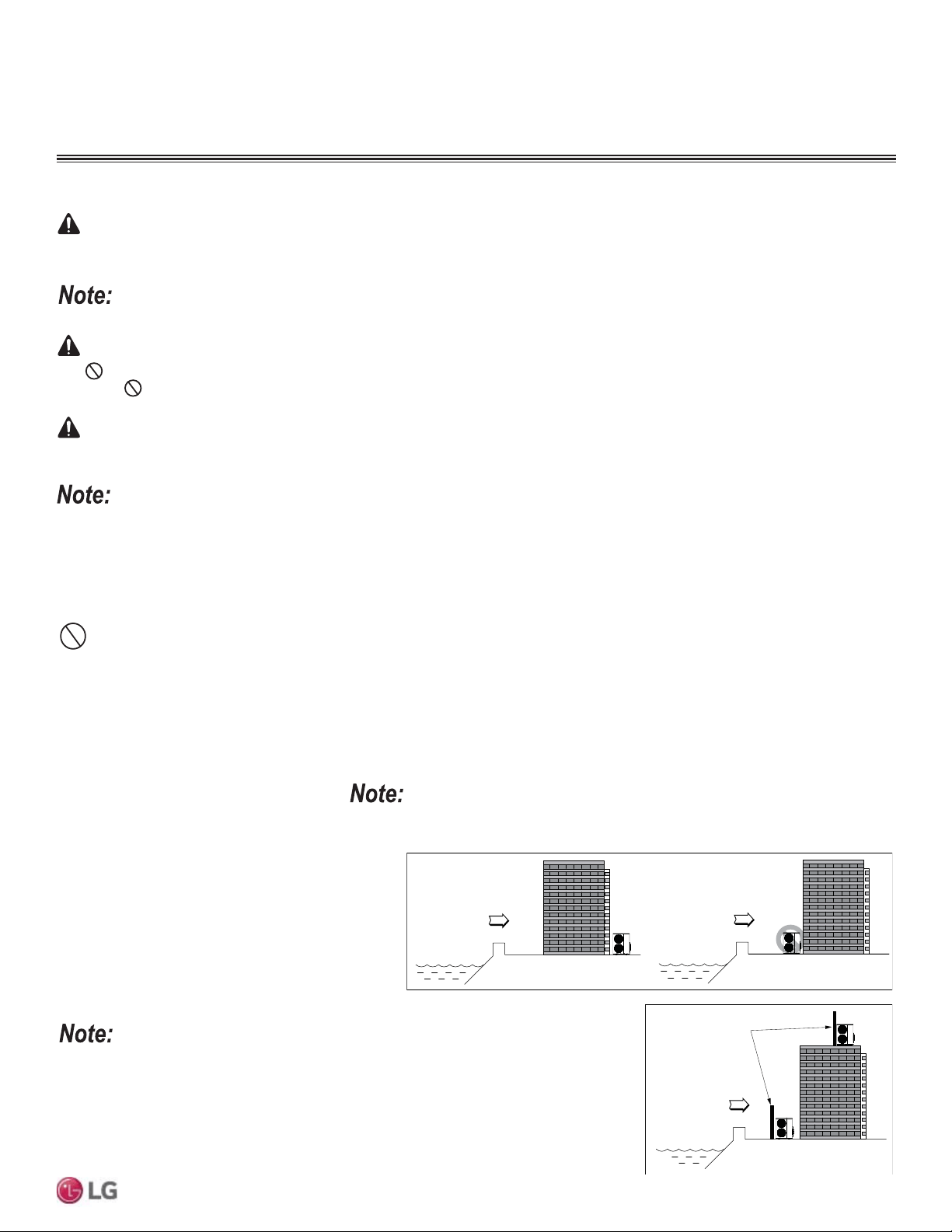
Ocean winds
Ocean winds
Ocean winds
Windbreaker
Oceanside Installation
Precautions
• Avoid installing the outdoor unit where it
would be directly exposed to ocean winds.
• Install the outdoor unit on the side of the
building opposite from direct ocean winds.
• Select a location with good drainage.
• Periodically clean dust or salt particles off of
the heat exchanger with water.
Additional anti-corrosion treatment may need
to be applied to the outdoor unit at oceanside
locations.
If the outdoor unit must be placed in a
location where it would be subjected to
direct ocean winds, install a concrete
windbreaker strong enough to block
any winds. Windbreaker height and
width should be more than 150% of the
outdoor unit, and be installed at least
27-1/2 inches away from the outdoor unit
to allow for airflow.
2FHDQZLQGVPD\FDXVHFRUURVLRQSDUWLFXODUO\RQWKHFRQGHQVHUDQGHYDSRUDWRU¿QV
ZKLFKLQWXUQFRXOGFDXVHSURGXFWPDOIXQFWLRQRULQHI¿FLHQWSHUIRUPDQFH
Before beginning installation, read the safety summary at the beginning of this manual.
14
MULTI F / MULTI F MAX Outdoor Unit Installation Manual
Due to our policy of continuous product innovation, some specifications may change without notification.
©LG Electronics U.S.A., Inc., Englewood Cliffs, NJ. All rights reserved. “LG” is a registered trademark of LG Corp.
MULTI
F
MAX
MULTI
F
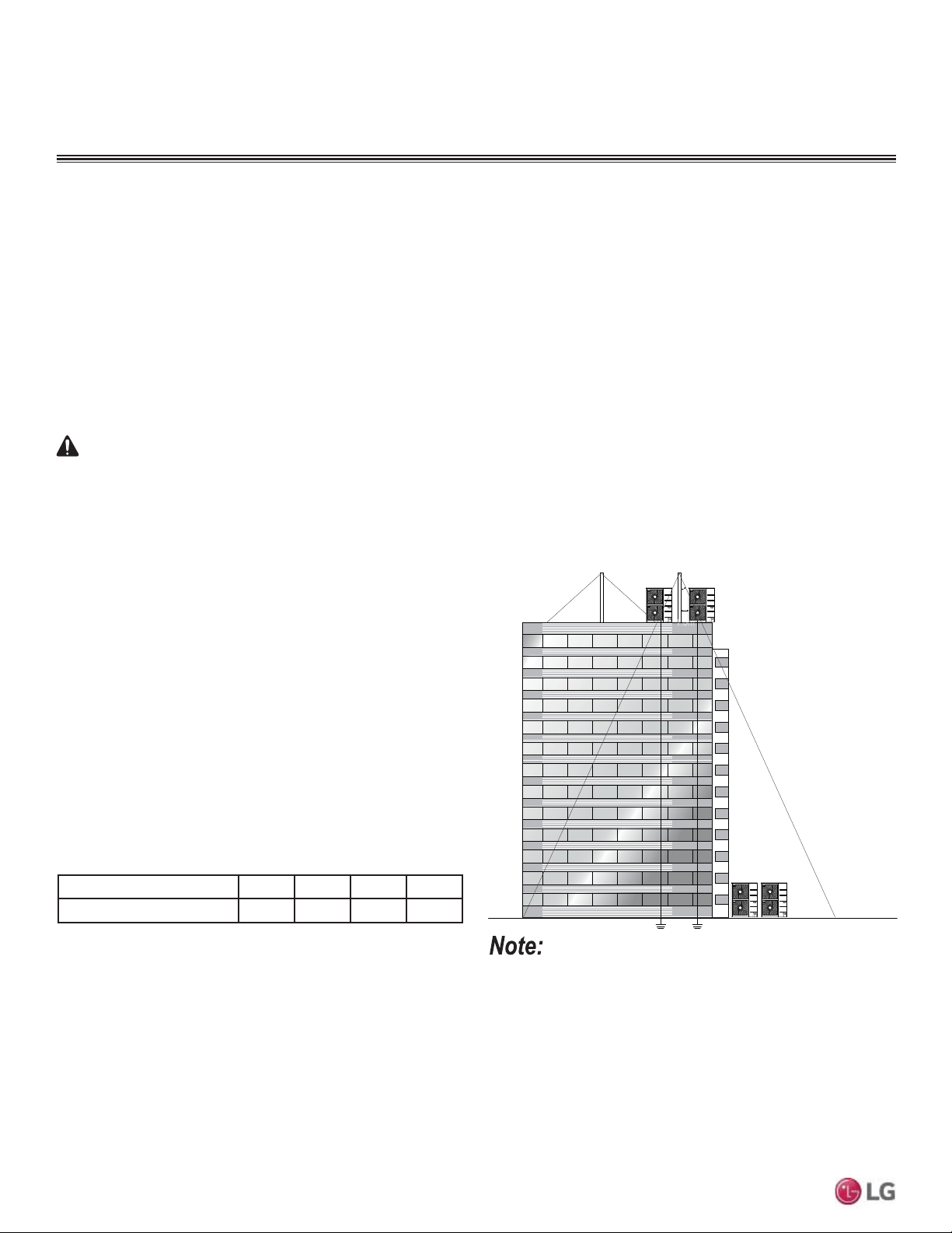
Tie-Downs and Lightning Protection
Tie-Downs
• The strength of the roof must be checked before installing the
outdoor units.
• If the installation site is prone to high winds or earthquakes, when
installing on the wall or roof, securely anchor the mounting base
using a field-provided tie-down configuration approved by a local
professional engineer.
• The overall tie-down configuration must be approved by a local
professional engineer. Always refer to local code when using a
wind restraint system.
Lightening Protection
• To protect the outdoor unit from lightning, it should be placed within
the specified lightning safety zone.
• Power cable and communication cable should be installed five (5)
feet away from lightning rod.
• A high-resistance ground system should be included to protect
against induced lightning or indirect strike.
Ground
Safe zone
Lightning rod
Protection Angle (25˚~55˚)
1.5m
5 feet
Lightning rod
Figure 1: Lightening Protection Diagram.
Table 6: 6DIHW\=RQH6SHFL¿FDWLRQV
Building Height (feet) 66 98 148 197
3URWHFWLRQ$QJOHÜ 55 45 35 25
If the building does not include lightning protection, the outdoor
unit may be damaged from a lightening strike. Inform the customer
of this possibility in advance.
GENERAL INSTALLATION GUIDELINES
Location for Outdoor Unit
Rooftop Installations
If the outdoor unit is installed on a roof structure, be sure to level the unit. Ensure the roof structure and anchoring method are adequate for
the unit location. Consult local codes regarding rooftop mounting.
Planning for Snow and Ice
In climates that experience snow buildup, place the unit on a raised platform to ensure proper condenser airflow. The raised support platform
must be high enough to allow the unit to remain above possible snow drifts. Mount the unit on a field-provided stand that is higher than the
maximum anticipated snowfall for the location. Design the mounting base to prevent snow accumulation on the platform in front or back of
the unit case. If necessary, provide a field fabricated hood to keep snow and ice and/or drifting snow from accumulating on the coil surfaces.
Use inlet and discharge duct or hoods to prevent snow or rain from accumulating on the fan inlet and outlet guards. Best practice prevents
snow from accumulating on top of the unit. Consider tie-down requirements in case of high winds or where required by local codes.
When deciding on a location to place the outdoor unit, be sure to choose an area where run-off from defrost will not accumulate and freeze
on sidewalks or driveways which may create unsafe conditions.
CAUTION
15
General Installation Guidelines
Due to our policy of continuous product innovation, some specifications may change without notification.
©LG Electronics U.S.A., Inc., Englewood Cliffs, NJ. All rights reserved. “LG” is a registered trademark of LG Corp.
MULTI
F
MAX
MULTI
F
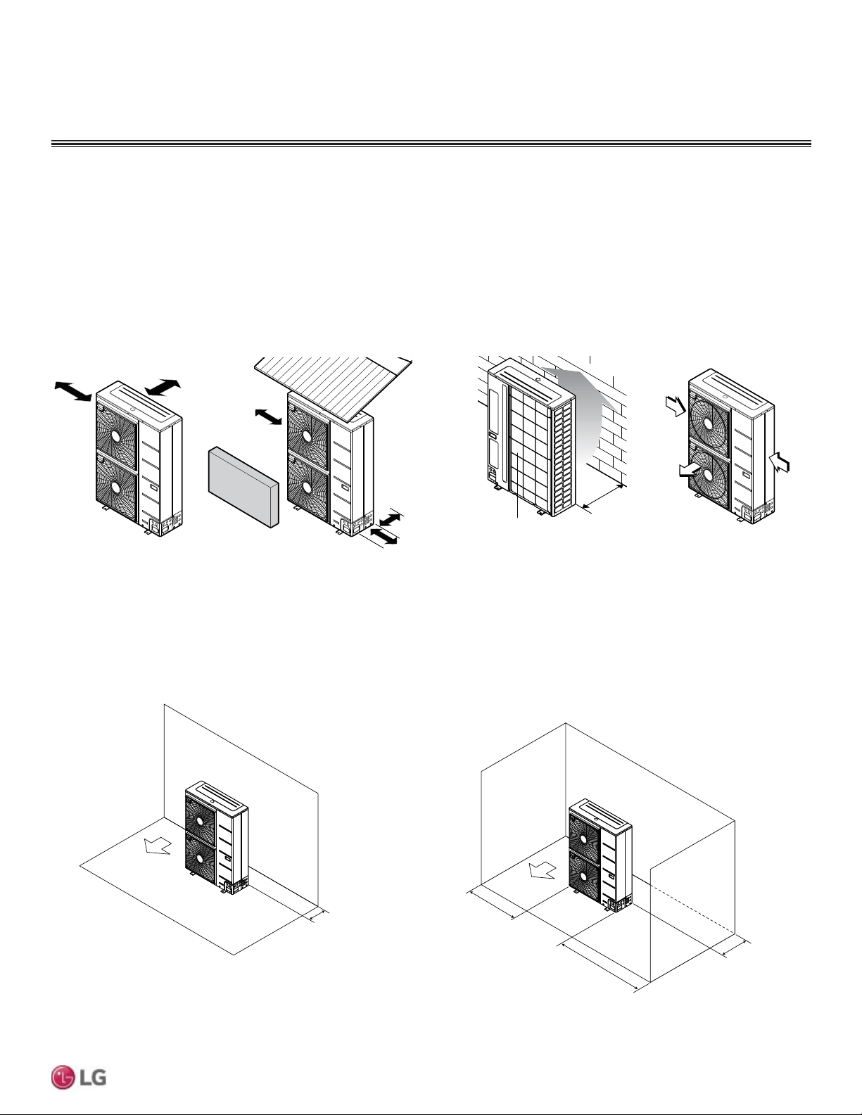
Clearance Requirements when Different Obstacles are Present (Unit: Inch)
Minimum 12"
Minimum 12"
Minimum 12
"
Minimum 24"
Obstacle on the suction side only. Obstacles on the suction side and
on both left and right sides.
Service Access and Allowable Clearances for Outdoor Unit
GENERAL INSTALLATION GUIDELINES
Minimum 12
Air inlet grille
Blown
air
Strong
wind
Strong
wind
Minimum 12
Minimum 24
Sunroof
Fence or
obstacles
Minimum 12
Air inlet grille
Blown
air
Strong
wind
Strong
wind
Minimum 20
Fence or
obstacles
Unit: Inch
Minimum 12
Ensure that the space at the back of the outdoor unit is a minimum of 11-13/16 inches, and
include a minimum of 23-5/8 inches at the right side of the unit for service.
If the outdoor unit discharge side faces a wall, include a minimum of 19-11/16 inches
between the outdoor unit and the wall. Install the outdoor unit so that the discharge port is
set at a right angle to the wind direction.
Outdoor Unit Service Access and Allowable Clearances
Appropriate airflow through the outdoor unit coil is critical for proper unit operation.
• Include enough space for airflow and for service access. If installing multiple outdoor units, avoid placing the units where the discharge of
one unit will blow into the inlet side of an adjacent unit.
• No obstacles to air circulation around the unit; keep proper distances from ceilings, fences, floor, walls, etc. (Install a fence to prevent pests
from damaging the unit or unauthorized individuals from accessing it.)
• If an awning is built over the unit to prevent direct sunlight or rain exposure, make sure that the discharge air of the outdoor unit isn’t restricted.
When installing the outdoor unit, consider service, inlet, and outlet, and minimum allowable space requirements as illustrated in the following
diagrams.
16
MULTI F / MULTI F MAX Outdoor Unit Installation Manual
Due to our policy of continuous product innovation, some specifications may change without notification.
©LG Electronics U.S.A., Inc., Englewood Cliffs, NJ. All rights reserved. “LG” is a registered trademark of LG Corp.
MULTI
F
MAX
MULTI
F
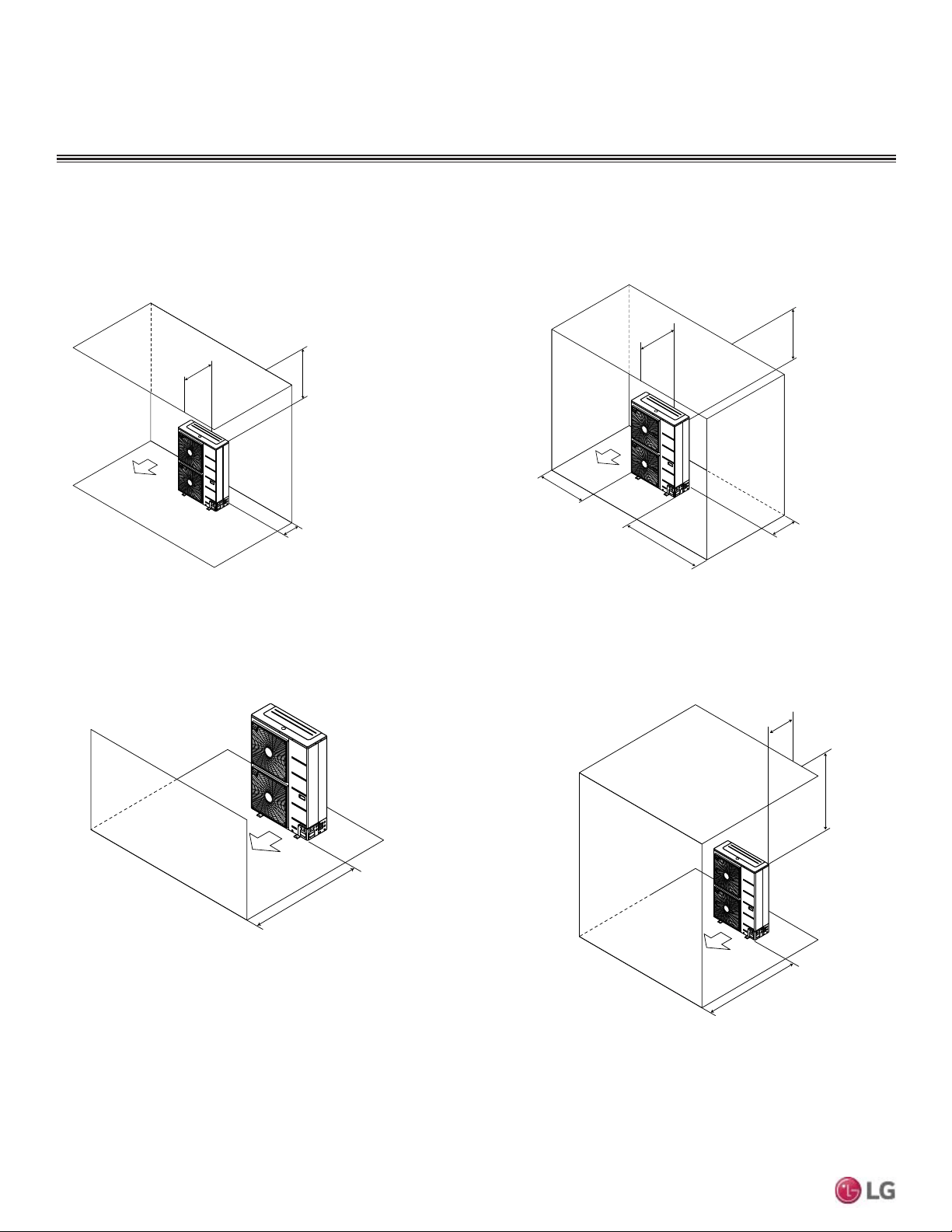
Minimum 12"
Minimum 20"
Minimum 40"
Minimum 12"
Maximum 20"
Minimum 12"
Minimum 40"
Minimum 24"
Obstacles above and on the air intake side. Obstacles above, on the air intake side,
and on both left and right sides
Minimum 20"
Minimum 20"
Minimum 20"
Minimum 40"
Obstacle just on the
air discharge side.
Obstacles above and on the
air discharge side.
Clearance Requirements when Different Obstacles are Present, continued. (Unit: Inch)
Allowable Clearances for Outdoor Unit
GENERAL INSTALLATION GUIDELINES
17
General Installation Guidelines
Due to our policy of continuous product innovation, some specifications may change without notification.
©LG Electronics U.S.A., Inc., Englewood Cliffs, NJ. All rights reserved. “LG” is a registered trademark of LG Corp.
MULTI
F
MAX
MULTI
F
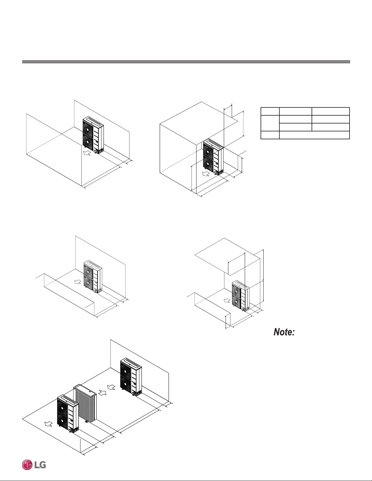
L
Minimum 40"
Minimum 40"
Maximum 20"
Minimum 12"
Where there are obstacles on both suction
and discharge sides (discharge side obstacle
is lower than the outdoor unit).
Where there are obstacles above, and on both
suction and discharge sides (discharge side obstacle
is lower than the outdoor unit).
Minimum 20"
Minimum 12"
H
Minimum 12"
Minimum 79"
Minimum 24"
Minimum 40"
Series installation
³/´VKRXOGEHORZHUWKDQ³+´,I
a stand is necessary, it should
be contained (not open frame)
to prevent the discharge air from
short cycling.
Allowable Clearances for Outdoor Unit
GENERAL INSTALLATION GUIDELINES
Where there are obstacles on both suction
and discharge sides (discharge side obstacle
is higher than the outdoor unit).
Minimum 20"
Minimum 12"
Table 7: Ratio among H, A, and L.
If a stand is necessary, it should be contained
(not open frame) to prevent the discharge air from
short cycling.
LA
L H
/+ 30 inches
1/2 H < L 40 inches
H < L 6HW6WDQGDV/+
Where there are obstacles above, and on both
suction and discharge sides (discharge side obstacle
is higher than the outdoor unit).
Maximum 20"
Minimum 12"
Minimum 40"
L
H
A
18
MULTI F / MULTI F MAX Outdoor Unit Installation Manual
Due to our policy of continuous product innovation, some specifications may change without notification.
©LG Electronics U.S.A., Inc., Englewood Cliffs, NJ. All rights reserved. “LG” is a registered trademark of LG Corp.
MULTI
F
MAX
MULTI
F
GENERAL INSTALLATION GUIDELINES
Rigging Instructions / Platform Instructions for Outdoor Unit
Rigging and Lifting Instructions
Be very careful when transporting the product. There is a risk of the product falling and causing physical injury.
• Use appropriate moving equipment to transport each frame; ensure the equipment is capable of supporting the weights listed.
• Some products use polypropylene bands for packaging.
Do not use polypropylene bands to lift the unit.
• Support the outdoor unit a minimum of four points to avoid slippage from rigging apparatus.
Wear protective gloves when handling equipment. Sharp edges may cause personal injury.
Dispose the packing materials safely.
• Packing materials, such as nails and other metal or wooden parts, may cause puncture wounds or other injuries.
• Tear apart and throw away plastic packaging bags so that children may not play with them and risk suffocation and death.
CAUTION
• Make sure the outdoor unit is in its original packaging to avoid damage during local transport.
• $WWKHWLPHRIGHOLYHU\WKHSDFNDJHVKRXOGEHFKHFNHGIRUDQ\GDPDJHH[WHULRUDQGLQWHULRU5HSRUWDQ\GDPDJHWRWKHFDUULHU
claims agent immediately.
• Handle the outdoor unit with care. Keep the outdoor unit upright to avoid damaging inside components.
• If a forklift is to transport the outdoor unit, the forklift arms should pass through the openings at the bottom.
• If a crane is to suspend the outdoor unit, it is recommended that two (2) ropes at least twenty-three (23) feet in length be used.
• Pass the ropes under the unit. Pass the rope through the two (2) forklift slots each at the front and rear of the outdoor unit.
• 7RSUHYHQWGDPDJHWRWKHRXWGRRUXQLWDOZD\VOLIWWKHXQLWZLWKWKHURSHVDWWDFKHGDWIRXUSRLQWVDWDQDQJOHRI
• Always include padding to protect the outdoor unit from rope damage, and take into consideration the outdoor unit’s center of gravity.
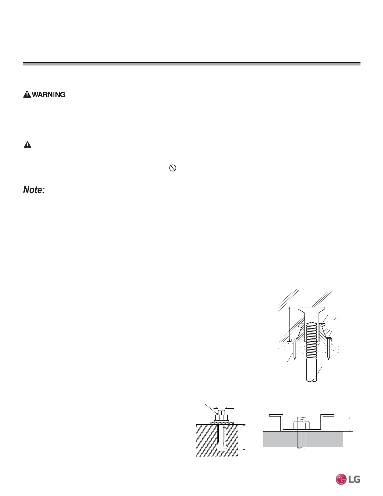
Anchoring the Outdoor Unit
• Tightly anchor the outdoor unit with a bolt and nut to a concrete or rigid platform.
• When installing on a wall (with field-supplied brackets), roof, or rooftop, securely anchor the
mounting platform with nails, taking into consideration the possibility of strong winds or earth-
quakes.
• If there is a possibility of vibration from the outdoor unit transmitting to the building, add an
anti-vibration material to the platform.
M10
Anchor Bolt
2-3/4~4-23/32
13/16
Unit: Inch
Figure 2: Example of Using an Insert for
a Hole in a Reinforced Concrete Beam.
Concrete Beam
Insert
Suspension Bolt
Polyblock /
Anti-Vibration
Material
Nail Securing
Polyblock
Concrete Platform Specifications
• Concrete foundations should be made of one part cement, two parts sand, and four parts gravel.
• The surface of the foundation should be finished with mortar with rounded edges, and weather-
proofed.
Figure 3: Close up of Bolt Attachment.
19
General Installation Guidelines
Due to our policy of continuous product innovation, some specifications may change without notification.
©LG Electronics U.S.A., Inc., Englewood Cliffs, NJ. All rights reserved. “LG” is a registered trademark of LG Corp.
MULTI
F
MAX
MULTI
F
Bolt
Refrigerant Pipe
Connection Location
Top of Outdoor Unit
(Looking Down)
Bolt
Bolt
Bolt
Bolting the Outdoor Unit to the Platform
1. Ensure that the concrete platform will not degrade easily, and has enough
strength to bear the weight of the unit.
2. Include an H-beam support. Firmly attach the corners, otherwise the support
will bend.
3. Use a hexagon nut.
4. Use anti-vibration material.
5. Include enough space around the concrete foundation for condensate
drainage.
6. Seal all wiring and piping access holes to prevent bugs from entering the
unit.
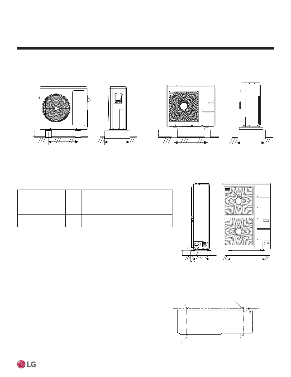
Outdoor Unit Foundation Requirements.
Figure 4: LMU18CHV and LMU24CHV Outdoor Units.
Minimum
7-7/8
7-7/8
15-3/4
Minimum 24-13/32
Unit: Inch
Outdoor Unit Type
Bolt
Type
Concrete Height Bolt Depth
LMU18CHV, LMU24CHV,
LMU30CHV, LMU36CHV
M10-J Minimum 4 inches Minimum 3 inches
LMU480HV, LMU540HV,
LMU600HV
M10-J Minimum 8 inches Minimum 3 inches
Table 8: 2XWGRRU8QLW)RXQGDWLRQ6SHFL¿FDWLRQV
Figure 5: LMU30CHV and LMU36CHV Outdoor Units.
Minimum
3-15/16
21-1/2
Minimum 14-9/16
Unit: Inch
Outdoor Unit Platform Requirements
Figure 6: LMU480HV, LMU540HV, LMU600HV Outdoor Units.
Figure 7: Bolting the Outdoor Unit to the Platform (Piping
Location May Differ Depending on Outdoor Unit Model).
Minimum
3-15/16)
21-1/2
Minimum 14-9/16
Unit: Inch
GENERAL INSTALLATION GUIDELINES
Platform Instructions for Outdoor Unit
20
MULTI F / MULTI F MAX Outdoor Unit Installation Manual
Due to our policy of continuous product innovation, some specifications may change without notification.
©LG Electronics U.S.A., Inc., Englewood Cliffs, NJ. All rights reserved. “LG” is a registered trademark of LG Corp.
MULTI
F
MAX
MULTI
F
GENERAL INSTALLATION GUIDELINES
Selecting the Best Location for the Branch Distribution (BD) Unit
Branch Distribution (BD) units are used only with Multi F MAX systems to distribute the refrigerant from the outdoor unit to up to eight indoor
units. Select location indoors that will meet the following conditions:
• Within allowable parameters for proper connection to the Multi F MAX outdoor unit and indoor unit(s); refrigerant piping and wire lengths
must not exceed amounts specified by LG Electronics, U.S.A., Inc.
• Condensate drain piping is not required.
• Ensure there is enough space in the installation area for service and inspection purposes (23-5/8 inch square opening).
• Install the refrigerant piping and electrical wiring system in an easily accessible location.
• Level where there is enough strength to bear the weight of the BD unit.
• Interior installation is highly recommended.
• $OORZDEOHRSHUDWLQJWHPSHUDWXUHUDQJHa)$OORZDEOHPD[LPXPRSHUDWLQJKXPLGLW\UDQJH
• Unit can be installed no more than ±5 degrees of level.
•
Do not install the BD unit in a location where it would be subjected to strong radiation heat from heat sources.
• Avoid an installation environment where the BD unit would be exposed to heat, water, steam, oil splattering, spray or other factors that may
damage the PCB.
• Install the unit in a location where any sound it generates will not disturb occupants in the surrounding rooms.
• No obstacles to air circulation around the unit; keep proper distances from ceilings, doorways, floor, walls, etc.
• Where high-frequency electrical noise / electromagnetic waves will not affect operation. Maintain proper distances between the BD unit(s)
and electric wires, audio and visual appliances, breaker / circuit panels, etc.
Location for Multi F MAX Branch Distribution Units
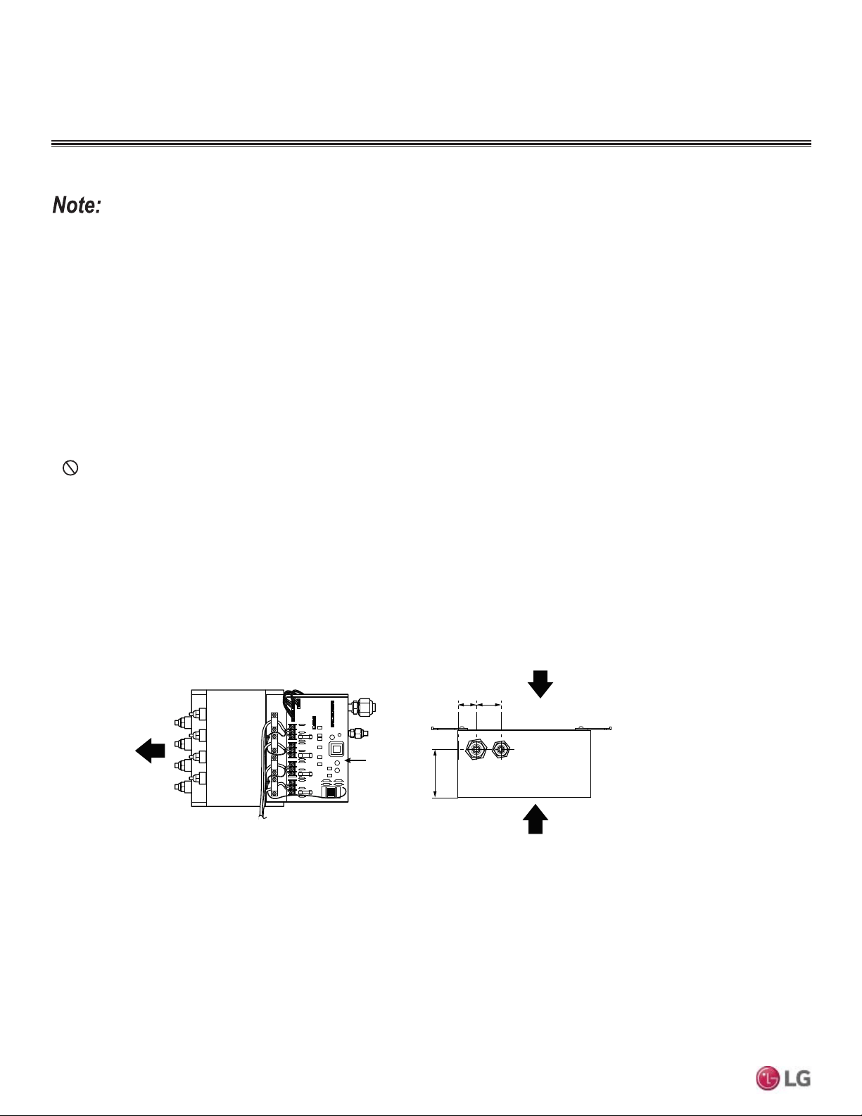
PCB
1-31/321-3/16
4-3/8
Service Direction
Piping to
Indoor Units
Service Direction
Figure 8: %UDQFK'LVWULEXWLRQ8QLW.H\&RPSRQHQWV
21
General Installation Guidelines
Due to our policy of continuous product innovation, some specifications may change without notification.
©LG Electronics U.S.A., Inc., Englewood Cliffs, NJ. All rights reserved. “LG” is a registered trademark of LG Corp.
MULTI
F
MAX
MULTI
F
GENERAL INSTALLATION GUIDELINES
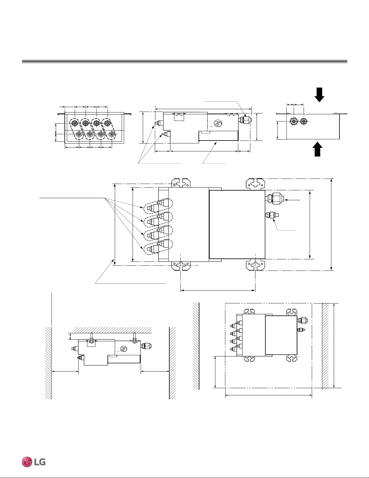
Location for Multi F MAX Branch Distribution Units
Figure 9: PMBD3620, PMBD3630, PMBD3640, and PMBD3641 External Dimensions.
1-31/32
1-3/16
4-3/8
Min 1-3/16
Min 15-3/4
Min 15-3/4
(Servicing space)
(Side view)
(Bottom view)
Unit: inch
1-31/32
1-31/32
1-31/32
1-31/32
1-23/32
1-31/32
1-31/32
1-31/32
2-7/32
1-1/2
Main Pipe
CoverBranch Pipe
2-3/8
11 -7/8
17
2-27/32
6-1/8
Inspection opening
23-5/8
9-27/32 or more
23-5/8
(EEV service)
(Controller service)
AB CD
Ø3/4
Ø3/8
Suspension bolt pitch.
*PMBD3641: D connections
- Ø3/8, Ø5/8
Liquid Pipe: Ø1/4
Gas Pipe: Ø3/8
9-7/16
13-9/32
ABC D
298(1 1-23/32)11-23/32
10-23/32
Notes
1. PMBD3620 unit supplied with "A, B"
2. PMBD3630 unit supplied with "A, B, C"
3.PMBD3640, PMBD3641 unit supplied with "A, B, C, D"
4. * Thickness of insulation
5-5/8
9-29/32
22
MULTI F / MULTI F MAX Outdoor Unit Installation Manual
Due to our policy of continuous product innovation, some specifications may change without notification.
©LG Electronics U.S.A., Inc., Englewood Cliffs, NJ. All rights reserved. “LG” is a registered trademark of LG Corp.
MULTI
F
MAX
MULTI
F
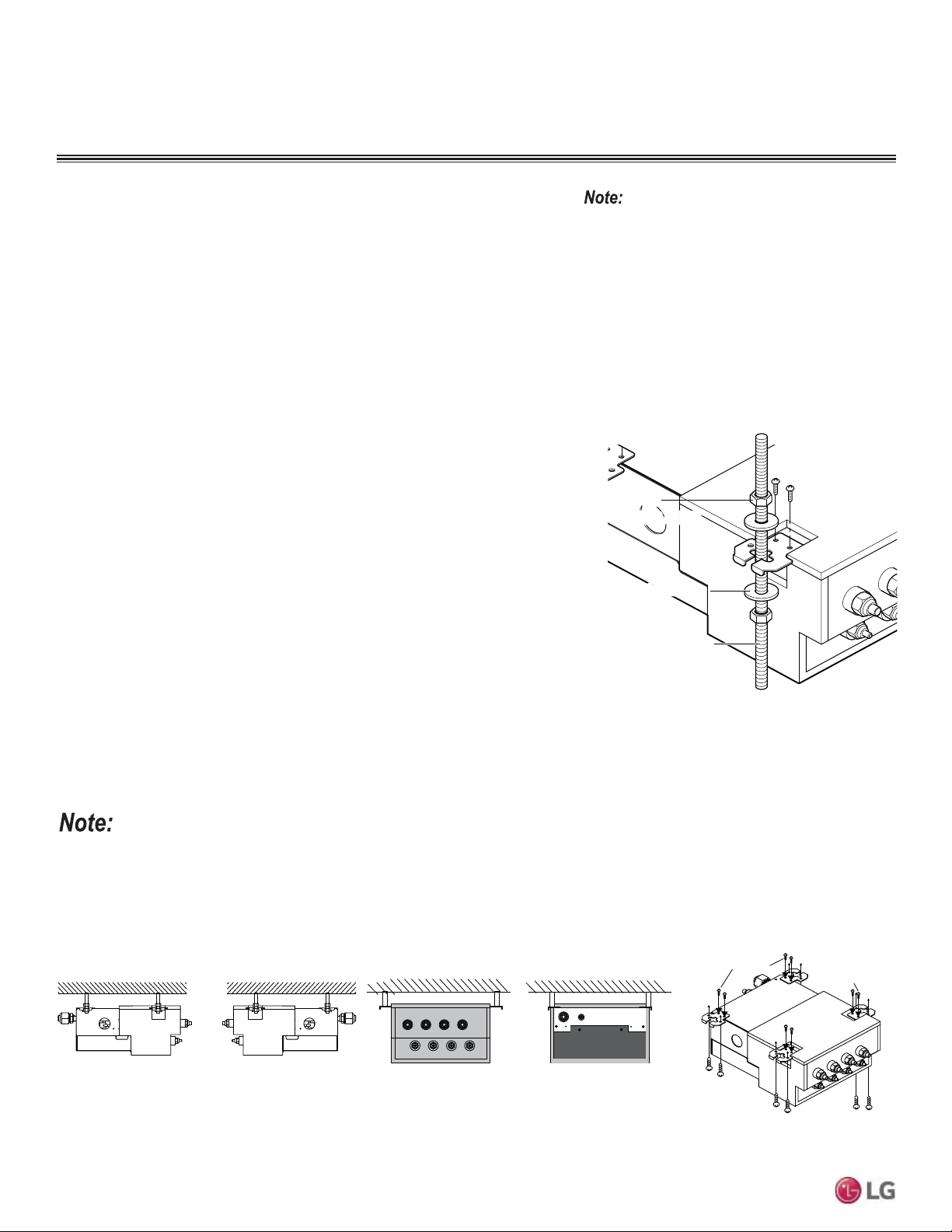
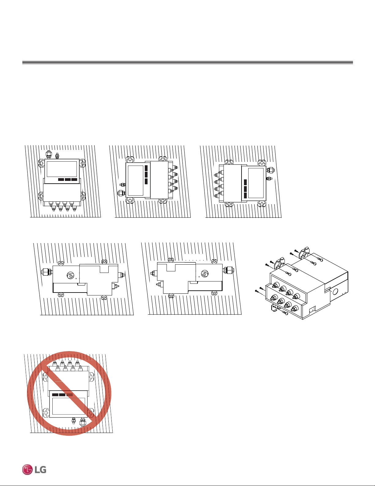
Branch Distribution Unit Orientation
Multi F MAX Branch Distribution (BD) Units can be installed in a multitude of
options to fit various building configurations and job or application requirements.
The installation location of the PCB within the BD unit can be changed for easier
service access, depending on the BD unit installation itself (see the wiring section
for information). Multi F MAX BD Units include electronic expansion valves that
properly seat only if the BD Unit is installed in an acceptable orientation. Installa-
tions with improper BD Unit orientation risk incomplete valve seating and system
performance degradation from potential refrigerant leakage through the electronic
expansion valve.
This material is for informational or educational
purposes only. It is not intended to be a substitute
for professional advice. Consult with your engineer
RUGHVLJQSURIHVVLRQDOVIRUVSHFL¿FDSSOLFDWLRQVWR
your system.
Figure 10: Acceptable BD Unit Ceiling Mount Orientations.
Left Side View,
Port End Facing Left
Ceiling Mounting Options
Port End View
Right Side View,
Port End Facing Right
Ceiling Ceiling
Ceiling
Top of Unit
Refrigerant Piping End View
Ceiling
Top of Unit
Top of Unit
Top of Unit
Top of Unit
Into the Ceiling
Into the Unit
Into the Ceiling
Into the Unit
Into the Unit
Into the Ceiling
Isometric View
Ceiling Mount Installation - Hangers with
Hanging Bolt
1. Drill four (4) holes in the ceiling, following the dimensions on the previous page.
2. Attach the factory-supplied hangers with two (2) screws each at the designated four
(4) areas on the frame of the BD unit.
3. Install an anchor in the ceiling, and attach the hanging bolts to the ceiling.
4. Add nuts and washers to the hanging bolt as shown at right.
5. Hang the BD unit on the hanging bolts (ceiling side up), and after checking for level
(±5 degrees), securely tighten all nuts.
BD unit
Nu t
(M10 or M8
Nut
(M10 or M8)
Flat washerFlat washer
Hanging bol tHanging bolt
(M10 or M8)
Figure 11: BD Ceiling Mount Installation.
If a screw has been installed on the frame of the BD unit and the screw has been removed, to prevent condensation, either re-install the
screw or cover the open hole with aluminum tape.
Ceiling Mount Installation - Hangers Only
1. Attach the factory-supplied hangers with two (2) screws each at the designated four
(4) areas on the frame of the BD unit.
2. Install the BD unit to the ceiling using two screws on each of the hangers as shown
below. Unit should be ±5 degrees of level.
3. Cover parts of the hanger holes with polyethylene foam insulation (to prevent con-
densation).
GENERAL INSTALLATION GUIDELINES
Multi F MAX Branch Distribution Unit Installation
23
General Installation Guidelines
Due to our policy of continuous product innovation, some specifications may change without notification.
©LG Electronics U.S.A., Inc., Englewood Cliffs, NJ. All rights reserved. “LG” is a registered trademark of LG Corp.
MULTI
F
MAX
MULTI
F
Bottom of Unit
Wall
Bottom View, Port End Facing Up
PCB
Bott
Figure 13: Unacceptable BD Unit Orientation.
Wall Mounting Options
Wall
Bottom View, Port End Down
PCB
PCB
Wall
Bottom
of Unit
PCB
Wall
Bottom View, Port End Facing Right
Bottom
of Unit
Bottom of Unit
Into the
Wall
Into the Unit
Into the Unit
Into the Wall
Into the Wall
Bottom of Unit
Isometric View
Bottom View, Port End Facing Left
Wall
Left Side View, Port End Facing Left
Wall
Top of Unit
Top of Unit
Right Side View, Port End Facing Right
Figure 12: Acceptable BD Unit Wall Mount Orientations.
Wall Mount Installation - Hangers Only
1. Attach the factory-supplied hangers with two (2) screws each at the designated four (4) areas on the frame of the BD unit.
2. Install the BD unit to the wall using two screws on each of the hangers. Unit should be ±5 degrees of level.
3. Cover parts of the hanger holes with polyethylene foam insulation (to prevent condensation).
GENERAL INSTALLATION GUIDELINES
Multi F MAX Branch Distribution Units Installation
24
MULTI F / MULTI F MAX Outdoor Unit Installation Manual
Due to our policy of continuous product innovation, some specifications may change without notification.
©LG Electronics U.S.A., Inc., Englewood Cliffs, NJ. All rights reserved. “LG” is a registered trademark of LG Corp.
MULTI
F
MAX
MULTI
F
Piping Preparation
GENERAL INSTALLATION GUIDELINES
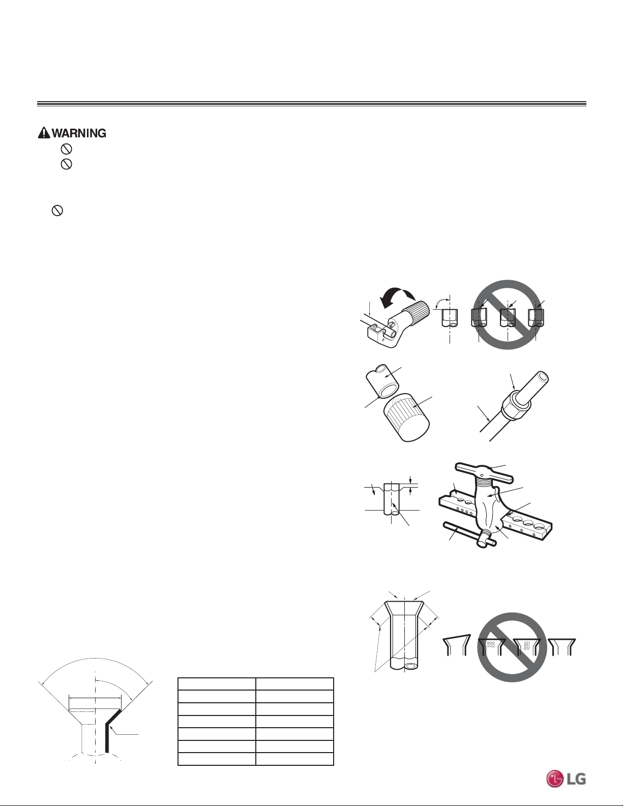
Creating a Flare Fitting
One of the main causes of refrigerant leaks is defective flared con-
nections. Create flared connections using the procedure below.
1. Cut the pipe to length.
• Measure the distance between the indoor unit and the outdoor unit.
• Cut the pipes a little longer than measured distance.
2A. Remove the burrs
• Completely remove all burrs from pipe ends.
• When removing burrs, point the end of the copper pipe down to
avoid introducing foreign materials in the pipe.
2B. Remove the flare nuts attached to the indoor and outdoor units.
Slide the flare nut onto the copper tube.
Table 9: Flared Connection Dimensions.
Copper
tube
90°
Slanted Uneven Rough
Pipe
Reamer
Point
down
Flare nut
Copper
tube
Bar
Copper pipe
Clamp handle
Red arrow
Cone
Yoke
Handle
Bar
"A"
Slanted
Inside is shiny with no scratches
Smooth
Even length
Damanged
surface
Cracked Uneven
thickness
Incorrect Flares
1.
2A. 2B.
3.
4.
3. Flaring the pipe end.
• Use the proper size flaring tool to finish flared connections as
shown.
• $/:$<6FUHDWHDIODUHZKHQZRUNLQJZLWK5$
• Firmly hold copper tube in a bar with a dimension as indicated in
the table below.
4. Carefully inspect the flared pipe end.
• Compare the geometry with the figures and dimensions as
detailed.
• If the flare is defective, cut it off and re-do procedure.
• If flare looks good, blow clean the pipe with dry nitrogen.
90°
2
45°
2
A
R=0.4~0.8
Figure 14: Dimensions of the Flare.
Outdoor Unit Pipe Connections
1. Do not use kinked pipe caused by excessive bending in one specific area on its length.
2. Braze the pipes to the service valve pipe stub of the outdoor unit.
3. After brazing, check for refrigerant gas leaks.
4. :KHQVHOHFWLQJIODUHILWWLQJVDOZD\VXVHDILWWLQJUDWHGIRUXVHZLWKKLJKSUHVVXUHUHIULJHUDQW5$6HOHFWHGILWWLQJVPXVWDOVR
comply with local, state, or federal standards.
•
'RQRWDOORZWKHUHIULJHUDQWWROHDNGXULQJEUD]LQJLIWKHUHIULJHUDQWFRPEXVWVLWJHQHUDWHVDWR[LFJDV
• Do not braze in an enclosed location, and always test for gas leaks before / after brazing.
• 7KHUHLVULVNRIILUHH[SORVLRQDQGSK\VLFDOLQMXU\RUGHDWK
Outside Diameter A
Inch Inch
Ø1/4 0.04 ~ 0.05
Ø3/8 0.06 ~ 0.07
Ø1/2 0.06 ~ 0.07
Ø5/8 0.06 ~ 0.07
Ø3/4 0.07 ~ 0.08
25
General Installation Guidelines
Due to our policy of continuous product innovation, some specifications may change without notification.
©LG Electronics U.S.A., Inc., Englewood Cliffs, NJ. All rights reserved. “LG” is a registered trademark of LG Corp.
MULTI
F
MAX
MULTI
F
Pipe size (Inches O.D.) Tightening torque (ft-lbs)
1/4Ø 13 ~ 18
3/8Ø 24.6 ~ 30.4
1/2Ø 39.8 ~ 47.7
5/8Ø 45.6 ~ 59.3
3/4Ø 71.6 ~ 87.5
Table 10: Tightening Torque for Flare Nuts.
Do not use polyolyester (POE) or any other type of mineral oil
as a thread lubricant. These lubricants are not compatible with PVE
oil used in this system and create oil sludge leading to equipment
damage and system malfunction.
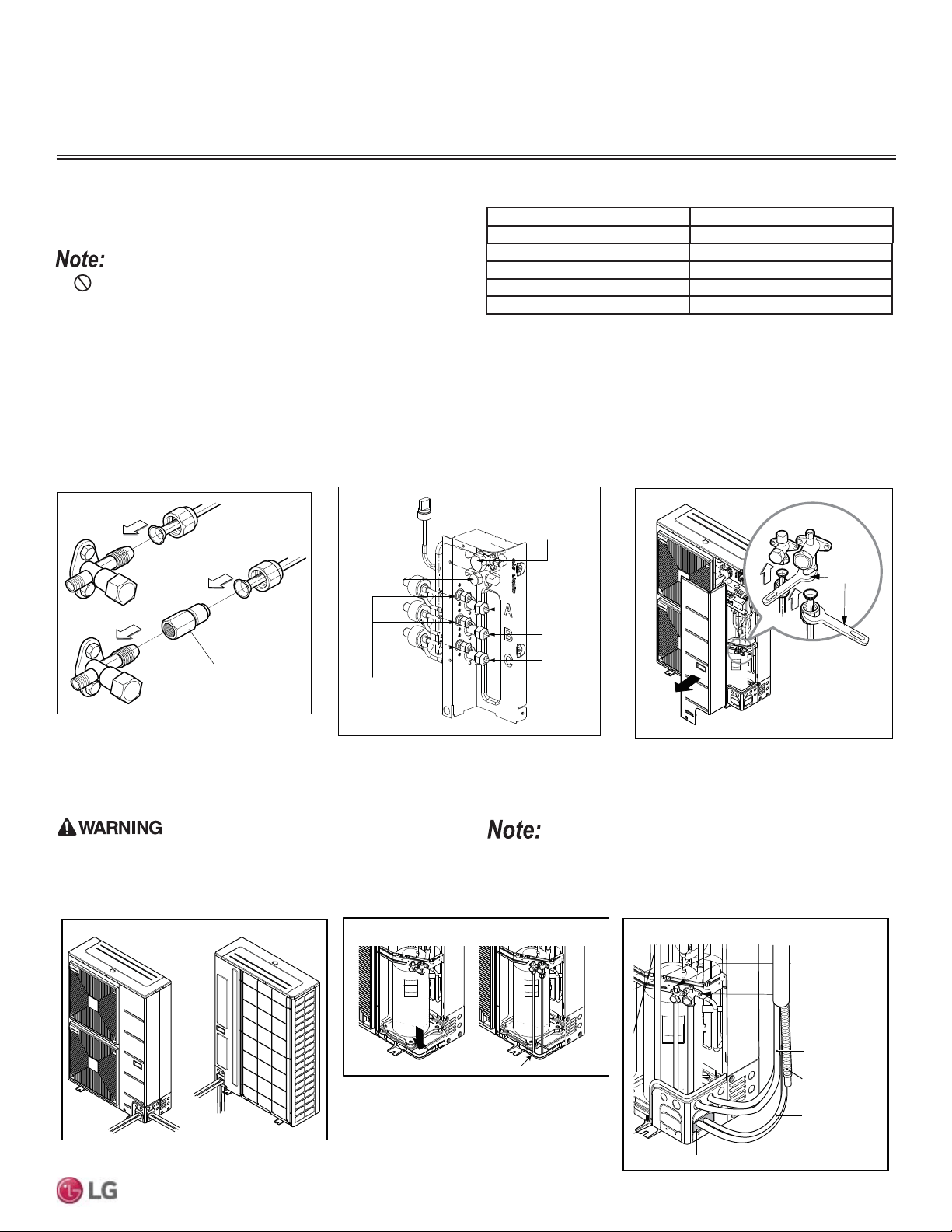
Tightening the Flare Connections
When connecting the flare nuts, coat the flare (outside only) with
polyvinyl ether (PVE) refrigeration oil only.
Ø1/2 Inch Connector
Liquid Piping
Main Liquid
Piping Valve
Main Gas
Piping Valve
ROOM A
ROOM B
ROOM C
Gas side
piping
For Multi F MAX outdoor units, piping can be installed in one of four directions: front, side, back, and down (A). If the downward installation is
chosen, the knockout hole in the base pan must be accessed (B).
Whatever direction is chosen, plug the access holes with field-provided putty or insulation to fill all gaps (C).
Continuous
Torque
Wrench
When tightening the
piping connection,
firmly hold the flare nut.
Front
Side
Back
Knockout Hole Base Pan
Down
Gas Piping
(Bigger Diameter)
Liquid Piping
(Smaller Diameter)
Putty or Insulation (field-supplied)
Drain Hose
Wire
Connection Pipe
A
B
C
Figure 15: Flare Connection. Figure 16: Example of Multi F Piping Connections. Figure 17: Multi F MAX Piping Connection.
Insects or small animals entering the outdoor unit may cause a short
FLUFXLWLQWKHHOHFWULFDOER[ZKLFKPD\OHDGWR¿UHHOHFWULFVKRFN
physical injury, or death.
Insects or small animals entering the outdoor unit may cause a short
FLUFXLWLQWKHHOHFWULFDOER[ZKLFKPD\OHDGWRXQLWIDLOXUH
Figure 18: Multi F MAX Piping Installation.
Align the center of the piping, and initially hand tighten the flare nuts using three (3) or four (4) turns. For Multi F Outdoor Units, install the
flare nuts by:
Then, to finish tighten the flare nut using the torque wrench and a backup wrench, following the direction arrows on the wrench and using the
appropriate tightening torque, until the wrench clicks. After all the piping has been connected, check for refrigerant gas leaks.
1. Connecting the Gas Piping for Connections A through D first. 2. Connecting the Liquid Piping for Connections A through D last.
GENERAL INSTALLATION GUIDELINES
Piping Preparation
26
MULTI F / MULTI F MAX Outdoor Unit Installation Manual
Due to our policy of continuous product innovation, some specifications may change without notification.
©LG Electronics U.S.A., Inc., Englewood Cliffs, NJ. All rights reserved. “LG” is a registered trademark of LG Corp.
MULTI
F
MAX
MULTI
F
Loosening the Flare Nuts
Always use two (2) wrenches to loosen the flare nuts.
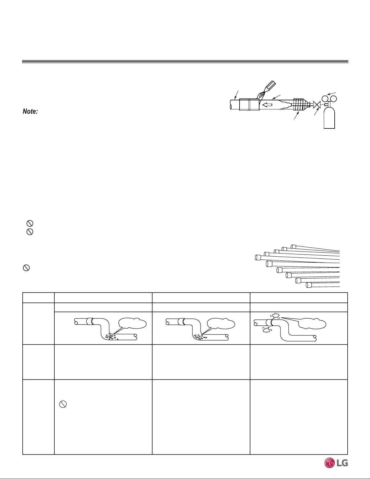
Piping Materials and Handling
Pipes used for the refrigerant piping system must include the specified thickness, and the
interior must be clean.
Do not bend or damage the pipes while handling and storing, and take care not to con-
taminate the interior with dust, moisture, etc. See Table 11 for care of piping.
Dry Clean Airtight
Principles No moisture should be inside the piping. No dust should be inside the piping. No leaks should occur.
Problems
Caused
- Significant hydrolysis of refrigerant oil.
- Refrigerant oil degradation.
- Poor insulation of the compressor.
- System does not operate properly.
- EEVs, capillary tubes are clogged.
- Refrigerant oil degradation.
- Poor insulation of the compressor.
- System does not operate properly.
- EEVs and capillary tubes become
clogged.
- Refrigerant gas leaks / shortages.
- Refrigerant oil degradation.
- Poor insulation of the compressor.
- System does not operate properly.
Solutions
- Remove moisture from the piping.
- Piping ends should remain capped until
connections are complete.
-
Do not install piping on a rainy day.
- Connect piping properly at the unit’s side.
- Remove caps only after the piping is
cut, the burrs are removed, and after
passing the piping through the walls.
- Evacuate system to a minimum of 500
microns and insure the vacuum holds at
that level for 24 hours
- Remove dust from the piping.
- Piping ends should remain capped until
connections are complete.
- Connect piping properly at the side of
the unit.
- Remove caps only after the piping is cut
and burrs are removed.
- Retain the cap on the piping when
passing it through walls, etc.
- Test system for air tightness.
- Perform brazing procedures that comply
with all applicable standards.
- Perform flaring procedures that comply
with all applicable standards.
- Perform flanging procedures that
comply with all applicable standards.
- Ensure that refrigerant lines are pressure
tested to 550 psig.
Moisture
Dust
Leaks
Figure 19: .HHS3LSLQJ&DSSHG:KLOH6WRULQJ
Table 11: Three Principles of Refrigerant Piping
Piping Materials and Handling
GENERAL INSTALLATION GUIDELINES
Figure 20: Refrigerant Pipe Brazing.
Pressure-reducing
Valve
Valve
Taping
Nitrogen
Pipe to
be brazed
Refrigerant
Piping
Brazing Practices
All joints are brazed in the field. Multi F / Multi F MAX refrigeration system components contain very small capillary tubes, small orifices,
electronic expansion valves, oil separators, and heat exchangers that can easily become blocked. Proper system operation depends on the
installer using best practices and utmost care while assembling the piping system.
• While brazing, use a dry nitrogen purge operating at a minimum pressure of three (3) psig and maintain a steady flow.
• Blow clean all pipe sections with dry nitrogen prior to assembly.
• Use a tubing cutter. De-burr and clean all cuts before assembly.
• 6WRUHSLSHVWRFNLQDGU\SODFH.HHSSLSHFDSSHGDQGFOHDQ
• Use adapters to assemble different sizes of pipe. Use a 15% silver phosphorous copper brazing alloy to avoid overheating and produce
good flow.
• Protect isolation valves, electronic expansion valves, and other heat-sensitive control components from excessive heat with a wet rag or a
heat barrier spray product.
•
Do not use flux, soft solder, or anti-oxidant agents.
•
Do not use a saw to cut pipe.
Keep the piping system free of contaminants and debris such as copper burrs, slag, or carbon
dust during installation. Contaminants can result in mechanical failure of the system.
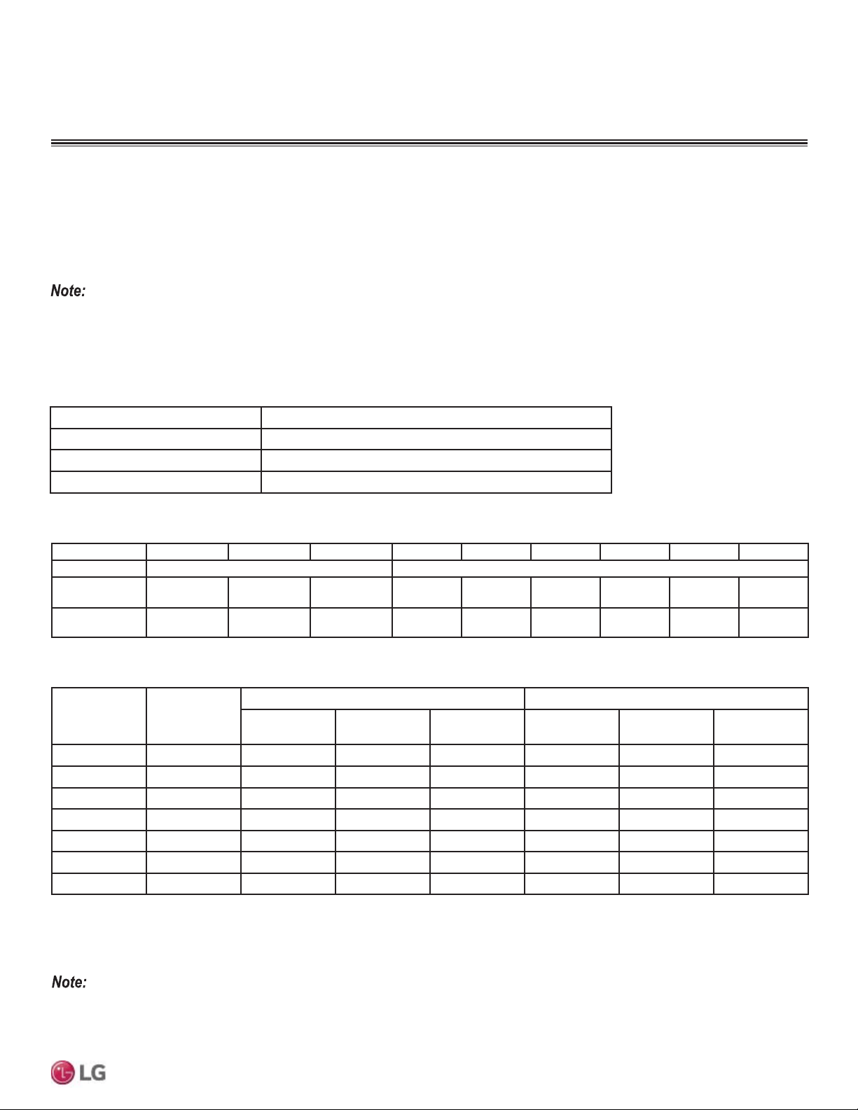
27
General Installation Guidelines
Due to our policy of continuous product innovation, some specifications may change without notification.
©LG Electronics U.S.A., Inc., Englewood Cliffs, NJ. All rights reserved. “LG” is a registered trademark of LG Corp.
MULTI
F
MAX
MULTI
F
Piping Materials and Handling
Table 13: ACR Copper Tubing Dimensions and Physical Characteristics
1-4
Nominal Pipe
Outside
Diameter (in)
Actual Outside
Diameter (in)
Drawn Temper Annealed Temper
Nominal Wall
Thickness (in)
Weight (lb/ft)
Cubic ft per
Linear ft
Nominal Wall
Thickness (in)
Weight (lb/ft)
Cubic ft per
Linear ft
1/4 0.250 -- -- -- 0.030 0.081 .00020
3/8 0.375 0.030 0.126 .00054 0.032 0.134 .00053
1/2 0.500 0.035 0.198 .00101 0.032 0.182 .00103
5/8 0.625 0.040 0.285 .00162 0.035 0.251 .00168
3/4 0.750 0.042 0.362 .00242 0.042 0.362 .00242
7/8 0.875 0.045 0.455 .00336 0.045 0.455 .00336
1-1/8 1.125 0.050 0.655 .00573 0.050 0.655 .00573
1
All dimensions provided are in accordance with ASTM B280 – Standard.
2
Design pressure = 551 psig.
3
ACR Tubing is available as hard drawn or annealed (soft) and are suitable for use with R410A refrigerant.
4
The Copper Tube Handbook, 2010, Copper Development Association Inc., 260 Madison Avenue, New York, NY 10016.
• Commercially available piping often contains dust and other materials. Always blow it clean with a dry inert gas.
• Prevent dust, water or other contaminants from entering the piping during installation. Contaminants can cause mechanical failure.
Selecting Field-Supplied Copper Tubing
Type ACR copper is the only approved refrigerant pipe material for use with LG Multi V S air conditioning products. ACR rated tubing is the
only type that ships with yellow caps. Approved tubing for use with Multi V products will be marked “R410 RATED” along the length of the
tube.
• Drawn temper (rigid) ACR copper tubing is available in sizes 3/8 through 2-1/8 inches (ASTM B 280, clean, dry, and capped).
• Annealed temper (soft) ACR copper tubing is available in sizes 1/4 through 2-1/8 inches (ASTM B 280, clean, dry, and capped).
Tube wall thickness should meet local code requirements and be approved for an operating pressure of 551 psi. If local code does not
VSHFLI\ZDOOWKLFNQHVV/*VXJJHVWVXVLQJWXEHWKLFNQHVVSHUWDEOHEHORZ:KHQEHQGLQJWXELQJWU\WRNHHSWKHQXPEHURIEHQGVWRDPLQLPXPDQG
use the largest radii possible to reduce the equivalent length of installed pipe; also, bending radii greater than ten (10) pipe diameters can minimize
pressure drop. Be sure no traps or sags are present when rolling out soft copper tubing coils.
Table 14: ACR Copper Tubing Material
Type Seamless Phosphorous Deoxidized
Class UNS C12200 DHP
Straight Lengths H58 Temper
Coils O60 Temper
OD (in) 1/4 3/8 1/2 5/8 3/4 7/8 1-1/8 1-3/8 1-5/8
Material 5LJLG7\SH³.´RU³/´DQG6RIW$&5$FFHSWDEOH 5LJLG7\SH³.´RU³/´2QO\
Min. Bend
Radius (in)
.563 .9375 1.5 3.0 3.0 3.0 3.5 4.0 4.5
Min. Wall
Thickness (in)
.031 .031 .031 .039 .042 .045 .050 .050 .050
Table 12: Piping Tube Thicknesses
GENERAL INSTALLATION GUIDELINES
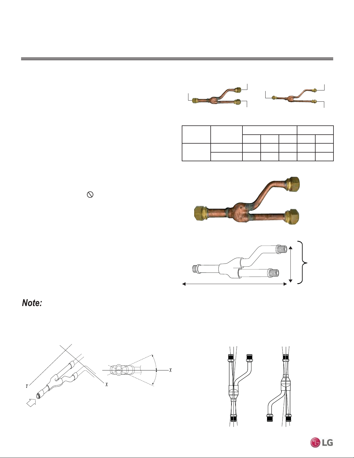
28
MULTI F / MULTI F MAX Outdoor Unit Installation Manual
Due to our policy of continuous product innovation, some specifications may change without notification.
©LG Electronics U.S.A., Inc., Englewood Cliffs, NJ. All rights reserved. “LG” is a registered trademark of LG Corp.
MULTI
F
MAX
MULTI
F
• Design pressure is 551 psig.
• All dimensions in inches. Tolerance ±1/4 inch.
• Images are not to scale.
Piping Materials and Handling
7KH/*VXSSOLHG<%UDQFK.LW30%/0867EHXVHGZKHQWZR
branch distribution units are connected on one Multi F MAX system.
Field-supplied fittings are not permitted. Each Y-Branch kit comes
with two (2) Y-branches (one for the liquid line and one for the vapor
line) and insulation covers.
Y-branches may be installed in horizontal or vertical configurations.
When installed vertically, position the Y-branch so the straight-
WKURXJKOHJLVRISOXPE:KHQLQVWDOOHGKRUL]RQWDOO\SRVLWLRQWKH
Y-branch so the take-off leg is level and shares the same horizontal
SODQHDVWKHVWUDLJKWWKURXJKOHJURWDWLRQ
Y-branches must be properly installed following instructions in the
applicable LG manual. Y-branches should always be installed with
the single port facing the outdoor unit and the two-port end facing
the branch distribution units.
Do not install Y-branches back-
wards as refrigerant flow cannot make U-turns. The Y-branch kit
must be located at least three (3) feet from the outdoor unit. Provide
a minimum of 20 inches between a Y-branch and the branch
distribution unit.
It is recommended that when a Y-branch is located in a pipe chase
or other concealed space, access doors should be provided for
inspection access.
7KHHTXLYDOHQWSLSHOHQJWKRIHDFK<EUDQFKƍPXVWEHDGGHG
to the main pipe segment entered into LATS Multi F piping design
software.
Figure 22: <%UDQFK3RUW,GHQWL¿HU'LDJUDP
Figure 23: Y-Branch Dimensions Diagram.
Figure 24: +RUL]RQWDO&RQ¿JXUDWLRQ(QG9LHZ
Multi F MAX Y-Branch Kit PMBL5620
Table 15: Y-Branch Connection Diameters.
Model
Y-Branch
Type
3RUW,GHQWLÀHULQFK Dimensions
123XY
PMBL5620
Liquid 3/8 3/8 3/8 13.80 3.24
Vapor 3/4 3/4 3/4 12.48 3.02
To Branch Distribution Unit Ø3/4
Ø3/4
To Outdoor Unit
Ø3/4
Ø3/8
Ø3/8
To Outdoor Unit
To Branch Distribution Unit Ø3/8
Figure 25: <EUDQFK,QVWDOODWLRQ$OLJQPHQW6SHFL¿FDWLRQ
Viewed from A in direction of arrow
Horizontal
plane
Within 5°
A
Within 5°
Vertical Up
Configuration
Within ± 3°Within ± 3°
Vertical Down
Configuration
A
B
X
Y
1
2
3
A = To Outdoor Unit B = To Branch Distribution Unit
1
2
3
Figure 21: Y-Branch Connections.
GENERAL INSTALLATION GUIDELINES
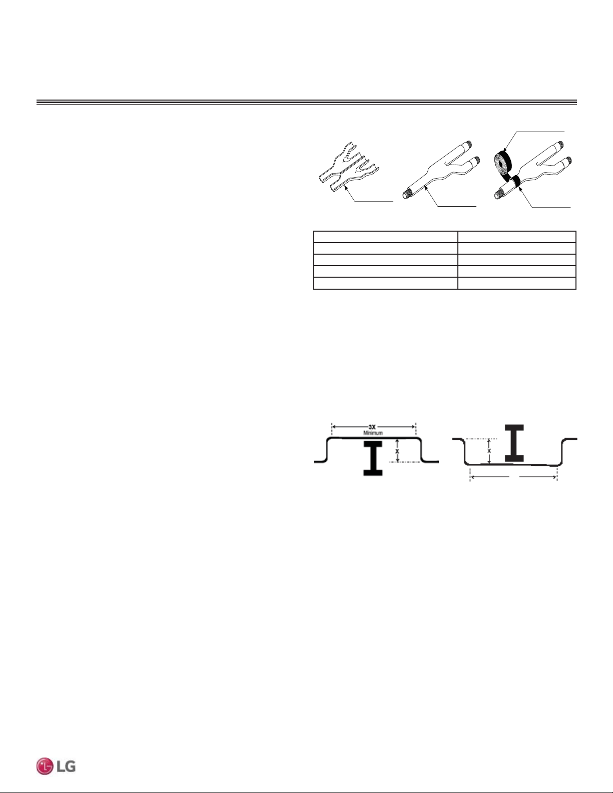
29
General Installation Guidelines
Due to our policy of continuous product innovation, some specifications may change without notification.
©LG Electronics U.S.A., Inc., Englewood Cliffs, NJ. All rights reserved. “LG” is a registered trademark of LG Corp.
MULTI
F
MAX
MULTI
F
Y-Branch Kit Insulation
Each Y-branch kit comes with clam-shell type peel-and-stick insu-
lation jackets molded to fit the Y-branch fittings—one for the liquid
line, one for the vapor line.
• Check the fit of the Y-branch clam-shell insulation jacket after the
Y-branch is installed.
• Mark the pipe where the insulation jacket ends.
• Remove the jacket.
• Install field-provided insulation on the pipes first.
• Peel the adhesive glue protector slip and install the clam-shell
jacket over the fitting
Liquid and Gas
Pipe Joints
Y-Branch Kit Insulation
Insulation for
Field-Installed Piping
Field-Supplied Insulation Tape
Figure 26: Y-branch Insulation Detail.
Material Polyolefin Foam
8/)ODPH&ODVVLÀFDWLRQ HF-1
Density 1.84 lbs./ft.
3
Thermal Conductivity .0208 Btu/h/ft. ºR
Thickness 1/2 inch
Table 16: Insulation Jacket Properties.
No Pipe Size Substitutions
Use only the pipe size selected by the LATS Multi F pipe system design software or as conveyed in the product installation instructions.
Using a different size is prohibited and may result in a system malfunction or failure to work at all.
Figure 27: Installing Piping Above and Below an Obstacle.
Above an obstacle.
3X
Minimum
Below an obstacle.
Obstacles
When an obstacle, such as an I-beam or concrete T, is in the path
of the planned refrigerant pipe run, it is best practice to route the
pipe over the obstacle. If adequate space is not available to route
the insulated pipe over the obstacle, then route the pipe under the
obstacle. In either case, it is imperative the horizontal section of pipe
above or below the obstacle be a minimum of three (3) times greater
than the longest vertical rise (or fall) distance.
Piping Materials and Handling
GENERAL INSTALLATION GUIDELINES

30
MULTI F / MULTI F MAX Outdoor Unit Installation Manual
Due to our policy of continuous product innovation, some specifications may change without notification.
©LG Electronics U.S.A., Inc., Englewood Cliffs, NJ. All rights reserved. “LG” is a registered trademark of LG Corp.
MULTI
F
MAX
MULTI
F
Under normal operating conditions, the vapor pipe temperature of a
0XOWL)V\VWHPFDQYDU\DVPXFKDV):LWKWKLVODUJH
variance in pipe temperature, the designer must consider pipe
expansion and contraction to avoid pipe and fitting fatigue failures.
Refrigerant pipe, along with the insulation jacket, form a cohesive
unit that expands and contracts together. During system operation,
thermal heat transfer occurs between the pipe and the surrounding
insulation.
If the pipe is mounted in free air space, no natural restriction to
movement is present if mounting clamps are properly spaced and
installed. When the refrigerant pipe is mounted underground in a
utility duct stacked among other pipes, natural restriction to linear
movement is present. In extreme cases, the restrictive force of
surface friction between insulating jackets could become so great
that natural expansion ceases and the pipe is “fixed” in place. In this
situation, opposing force caused by change in refrigerant fluid/vapor
temperature can lead to pipe/fitting stress failure.
The refrigerant pipe support system must be engineered to allow
free expansion to occur. When a segment of pipe is mounted
between two fixed points, provisions must be provided to allow pipe
expansion to naturally occur. The most common method is the
inclusion of expansion Loop or U-bends mounted in the horizontal
plane. When expansion loops are placed in a vertical riser, the loop
is to be formed in a horizontal fashion resulting in a torsional move-
ment during expansion and contraction. Each segment of pipe has
a natural fixed point where no movement occurs. This fixed point is
located at the center point of the segment assuming the entire pipe
is insulated in a similar fashion. The natural fixed point of the pipe
segment is typically where the expansion Loop or U-bend should be.
Linear pipe expansion can be calculated using the following formula:
1. From Table 17, find the row corresponding with the actual length
of the straight pipe segment.
2. Estimate the minimum and maximum temperature of the pipe.
Typical pipe temperature change range: High Pressure Vapor:
DPELHQWWHPSHUDWXUHWR)/RZ3UHVVXUH9DSRUDPELHQWWR
)/LTXLGSLSHDPELHQW))&KRRVHWKHWZRPRVW
extreme. In the column showing the minimum pipe temperature,
look up the anticipated expansion distance. Do the same for the
maximum pipe temperature.
3. Calculate the difference in the two expansion distance values.
The result will be the anticipated change in pipe length.
Example:
A Multi F MAX system is installed and the design shows that there
is a 100 foot straight segment of tubing between a Y-branch and
a branch distribution unit. The system operates 24 hours per day.
In heating, this pipe transports hot gas vapor to the indoor units at
),QFRROLQJWKHVDPHWXEHLVDVXFWLRQOLQHUHWXUQLQJUHIULJ-
HUDQWYDSRUWRWKHRXWGRRUXQLWDW)/RRNXSWKHFRSSHUWXELQJ
expansion at each temperature and calculate the difference.
Vapor Line
7UDQVSRUWLQJ+RW9DSRUIWSLSHDW) LQ
7UDQVSRUWLQJ6XFWLRQ9DSRUIWSLSHDW) LQ
Anticipated Change in Length: 1.40 in. – 0.40 in. = 1.00 in.
Liquid Line
The liquid temperature remains the same temperature; only the
direction of flow will reverse. Therefore, no significant change in
length of the liquid line is anticipated.
When creating an expansion joint, the joint depth should be a
minimum of two times the joint width. Although different types of
expansion arrangements are available, the data for correctly sizing
an expansion loop is provided in Table 18. Use soft copper with
long radius bends on longer runs or long radius elbows for shorter
pipe segments. Using the anticipated linear expansion (LE) distance
calculated, look up the Expansion Loop or U-bend minimum design
dimensions. If other types of expansion joints are chosen, design
per ASTM B-88 Standards.
LE = C x L x (T
r
– T
a
) x 12
LE = Anticipated linear tubing expansion (in.)
C = Constant (For copper = 9.2 x 10
-6
LQLQ)
L = Length of pipe (ft.)
T
R
5HIULJHUDQWSLSHWHPSHUDWXUH)
T
a
$PELHQWDLUWHPSHUDWXUH)
12 = Inches to feet conversion (12 in./ft.)
Copper Expansion and Contraction
Piping Materials and Handling
GENERAL INSTALLATION GUIDELINES
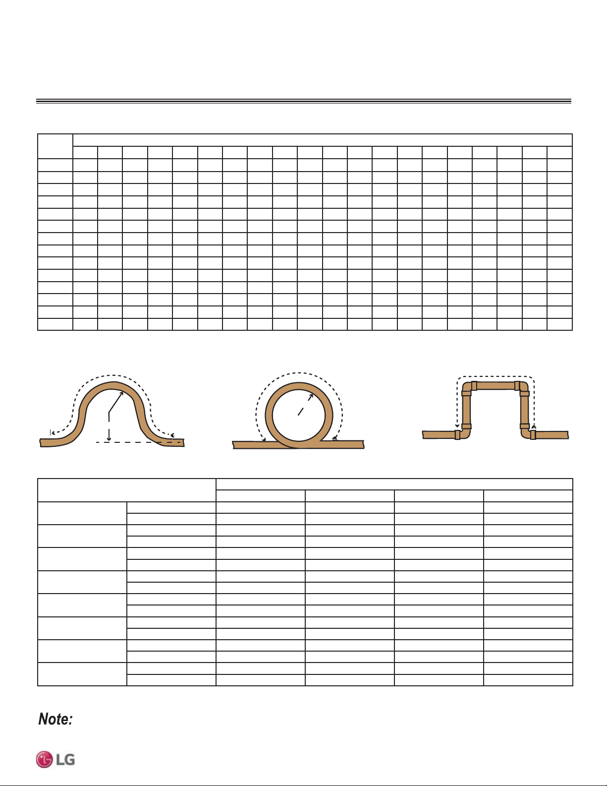
31
General Installation Guidelines
Due to our policy of continuous product innovation, some specifications may change without notification.
©LG Electronics U.S.A., Inc., Englewood Cliffs, NJ. All rights reserved. “LG” is a registered trademark of LG Corp.
MULTI
F
MAX
MULTI
F
Pipe
Length
1
Fluid Temperature °F
35° 40° 45° 50° 55° 60° 65° 70° 75° 80° 85° 90° 95° 100° 105° 110° 115° 120° 125° 130°
10 0.04 0.04 0.05 0.06 0.06 0.07 0.08 0.08 0.09 0.09 0.10 0.10 0.11 0.11 0.11 0.12 0.13 0.14 0.15 0.15
20 0.08 0.08 0.10 0.12 0.13 0.14 0.15 0.16 0.17 0.18 0.19 0.20 0.21 0.22 0.22 0.23 0.26 0.28 0.29 0.30
30 0.12 0.12 0.15 0.18 0.20 0.21 0.23 0.24 0.26 0.27 0.29 0.30 0.32 0.33 0.32 0.35 0.39 0.42 0.44 0.45
40 0.16 0.16 0.20 0.24 0.26 0.28 0.30 0.32 0.34 0.36 0.38 0.40 0.42 0.44 0.43 0.46 0.52 0.56 0.58 0.60
50 0.20 0.20 0.25 0.30 0.33 0.35 0.38 0.40 0.43 0.45 0.48 0.50 0.53 0.55 0.54 0.58 0.65 0.70 0.73 0.75
60 0.24 0.24 0.30 0.36 0.39 0.42 0.45 0.48 0.51 0.54 0.57 0.60 0.63 0.66 0.65 0.69 0.78 0.84 0.87 0.90
70 0.28 0.28 0.35 0.42 0.46 0.49 0.53 0.56 0.60 0.63 0.67 0.70 0.74 0.77 0.76 0.81 0.91 0.98 1.02 1.05
80 0.32 0.32 0.40 0.48 0.52 0.56 0.60 0.64 0.68 0.72 0.76 0.80 0.84 0.88 0.86 0.92 1.04 1.12 1.16 1.20
90 0.36 0.36 0.45 0.54 0.59 0.63 0.68 0.72 0.77 0.81 0.86 0.90 0.95 0.99 0.97 1.04 1.17 1.26 1.31 1.35
100 0.40 0.40 0.50 0.60 0.65 0.70 0.75 0.80 0.85 0.90 0.95 1.00 1.05 1.10 1.08 1.15 1.30 1.40 1.45 1.50
120 0.48 0.48 0.60 0.72 0.78 0.84 0.90 0.96 1.02 1.08 1.14 1.20 1.26 1.32 1.30 1.38 1.56 1.68 1.74 1.80
140 0.56 0.56 0.70 0.84 0.91 0.98 1.05 1.12 1.19 1.26 1.33 1.40 1.47 1.54 1.51 1.61 1.82 1.96 2.03 2.10
160 0.64 0.64 0.80 0.96 1.04 1.12 1.20 1.28 1.36 1.44 1.52 1.60 1.68 1.76 1.73 1.84 2.08 2.24 2.32 2.40
180 0.72 0.72 0.90 1.08 1.17 1.26 1.35 1.44 1.53 1.62 1.71 1.80 1.89 1.98 1.94 2.07 2.34 2.52 2.61 2.70
1
3LSHOHQJWKEDVHOLQHWHPSHUDWXUH )([SDQVLRQRI&DUERQ&RSSHUDQG6WDLQOHVV6WHHO3LSH7KH(QJLQHHUV7RROER[, www.engineeringtoolbox.com.
Table 17: Linear Thermal Expansion of Copper Tubing in Inches.
Large Tubing U-bend (>3/4 in.)
Loop
Small Tubing U-bend (<3/4 in.)
Figure 28: Coiled Expansion Loops and Offsets (Plan View shown).
R
L
Table 18: Radii of Coiled Expansion Loops and Developed Lengths of Expansion Offsets.
R
L
L
Anticipated Linear Expansion (LE) (inches)
Nominal Tube Size (OD) inches
1/4 3/8 1/2 3/4
1/2
R
1
6789
L
2
38 44 50 59
1
R
1
9101113
L
2
54 63 70 83
1-1/2
R
1
11 12 14 16
L
2
66 77 86 101
2
R
1
12 14 16 19
L
2
77 89 99 117
2-1/2
R
1
14 16 18 21
L
2
86 99 111 131
3
R
1
15 17 19 23
L
2
94 109 122 143
3-1/2
R
1
16 19 21 25
L
2
102 117 131 155
4
R
1
17 20 22 26
L
2
109 126 140 166
1
R = Centerline Length of Pipe.
2
L = Centerline Minimum Radius (inches).
$OOH[SDQVLRQ/RRSVDQG2IIVHWVVKRXOGEHLQVWDOOHGLQWKHKRUL]RQWDOSODQHWRSUHYHQWWKHSRVVLELOLW\RIWUDSSLQJRLO/RRSVDQG2IIVHWVLQ
vertical risers should also be installed in a horizontal plane.
Piping Materials and Handling
GENERAL INSTALLATION GUIDELINES
32
MULTI F / MULTI F MAX Outdoor Unit Installation Manual
Due to our policy of continuous product innovation, some specifications may change without notification.
©LG Electronics U.S.A., Inc., Englewood Cliffs, NJ. All rights reserved. “LG” is a registered trademark of LG Corp.
MULTI
F
MAX
MULTI
F
Pipe Slope
7KHKRUL]RQWDOSLSHVORSHFDQQRWH[FHHGXSRUGRZQ
In-line Refrigeration Components
Components such as oil traps, solenoid valves, filter-dryers, sight glasses, tee fittings, and other after-market accessories are not permitted
on the refrigerant piping system between the outdoor units and the indoor / branch distribution units. Multi F and Multi F MAX systems are
provided with redundant systems that assure oil is properly returned to the compressor. Sight-glasses and solenoid valves may cause vapor
to form in the liquid stream. Over time, dryers may deteriorate and introduce debris into the system. The designer and installer should verify
the refrigerant piping system is free of traps, sagging pipes, sight glasses, filter dryers, etc.
Pipe Bends
When bending soft copper, use long radius bends. Refer to the “Radii of Coiled Expansion Loops and Developed Lengths of Expansion
Offsets” table for minimum radius specifications, page 18.
Using Elbows
Field supplied elbows are allowed as long as they are designed for use with R410A refrigerant. The designer and installer, however, should
be cautious with the quantity and size of fittings used, and must account for the additional pressure losses in equivalent pipe length calcula-
tion for each branch. The equivalent pipe length of each elbow must be added to each pipe segment in the LATS program. See page 35 for
equivalent lengths.
GENERAL INSTALLATION GUIDELINES
Piping Materials and Handling
Field-Provided Isolation Ball Valves
LG maintains a neutral position on using isolation valves in VRF refrigerant piping systems. LG does not endorse any manufacturer of isola-
tion valves. It is recognized that installing isolation valves may simplify future maintenance requirements, and, if used, considerations should
be taken including, but not limited to, the following:
• Pressure drops for any component used, including isolation valves, must be known in equivalent pipe length and calculated into the total
and segment equivalent piping lengths and compared to product design limitations.
• In all cases, materials must be suitable for the application and any applicable codes, including, but not limited to, diameter and wall
thickness continuity per ACR standards.
Failure to do so may cause significant performance degradation. Proper leak checks must be performed. Using isolation valves does not
automatically void any LG product warranty; however, a limited warranty may be voided in whole or part should any field supplied accessory
fail in any way that causes product failure.
/*(OHFWURQLFV86$,QFLVQRWUHVSRQVLEOHIRUDQ\SLSLQJFDOFXODWLRQVUHIULJHUDQWOHDNVGHJUDGDWLRQRISHUIRUPDQFHRUDQ\RWKHUSRWHQWLDO
problems or damages as a result of interconnecting piping, their joint connections, isolation valves, introduced debris inside the piping system,
or other problems caused by the interconnecting piping system.
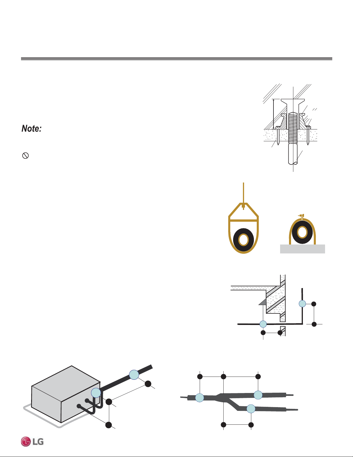
33
General Installation Guidelines
Due to our policy of continuous product innovation, some specifications may change without notification.
©LG Electronics U.S.A., Inc., Englewood Cliffs, NJ. All rights reserved. “LG” is a registered trademark of LG Corp.
MULTI
F
MAX
MULTI
F
Pipe Supports
Figure 29: Installing an Insert Into
a Concrete Beam.
Piping Materials and Handling
Inserts and Pipe Supports
Inserts
An insert can be installed into a floor or beam before the concrete sets so that fittings such as ducts,
pipes, or suspension bolts can be added at a later time. Decide where the inserts should be placed
before support installation.
Figure 30: Pipe Hanger Details.
A
B
A + B ~ 12" – 19"
Max. 12" Max. 12"
Max. 12"
Figure 31: Typical Pipe Support Location—Change
in Pipe Direction.
Max. 12"
~ 12" – 19"
Pipe supports should never touch the pipe wall; supports shall be installed outside
(around) the primary pipe insulation jacket.
Insulate the pipe first because pipe supports shall be installed outside (around) the
primary pipe insulation jacket. Clevis hangers should be used with shields between the
hangers and insulation.
Field provided pipe supports should be designed to meet local codes. If allowed by
code, use fiber straps or split-ring hangers suspended from the ceiling on all-thread rods
(fiber straps or split ring hangers can be used as long as they do not compress the pipe
insulation). Place a second layer of insulation over the pipe insulation jacket to prevent
chafing and compression of the primary insulation within the confines of the support pipe
clamp.
A properly installed pipe system will have sufficient supports to avoid pipes from sagging
during the life of the system. As necessary, place supports closer for segments where
potential sagging could occur. Maximum spacing of pipe supports shall meet local
codes. If local codes do not specify pipe support spacing, pipe shall be supported a
maximum of five (5) feet on center for straight segments of pipe up to 3/4” outside
diameter size.
Wherever the pipe changes direction, place a hanger within twelve (12) inches on one
side and within twelve to nineteen (12 to 19) inches of the bend on the other side. Sup-
port piping at indoor units as shown. Support Y-Branch fittings as shown.
A properly installed pipe system should be adequately supported to avoid pipe sagging. Sagging pipes
become oil traps that lead to equipment malfunction.
Figure 32: Pipe Support at Indoor Unit.
Figure 33: Pipe Support at Y-branch Fitting.
GENERAL INSTALLATION GUIDELINES
Concrete Beam
Insert
Suspension Bolt
Polyblock /
Anti-Vibration
Material
Nail Securing
Polyblock
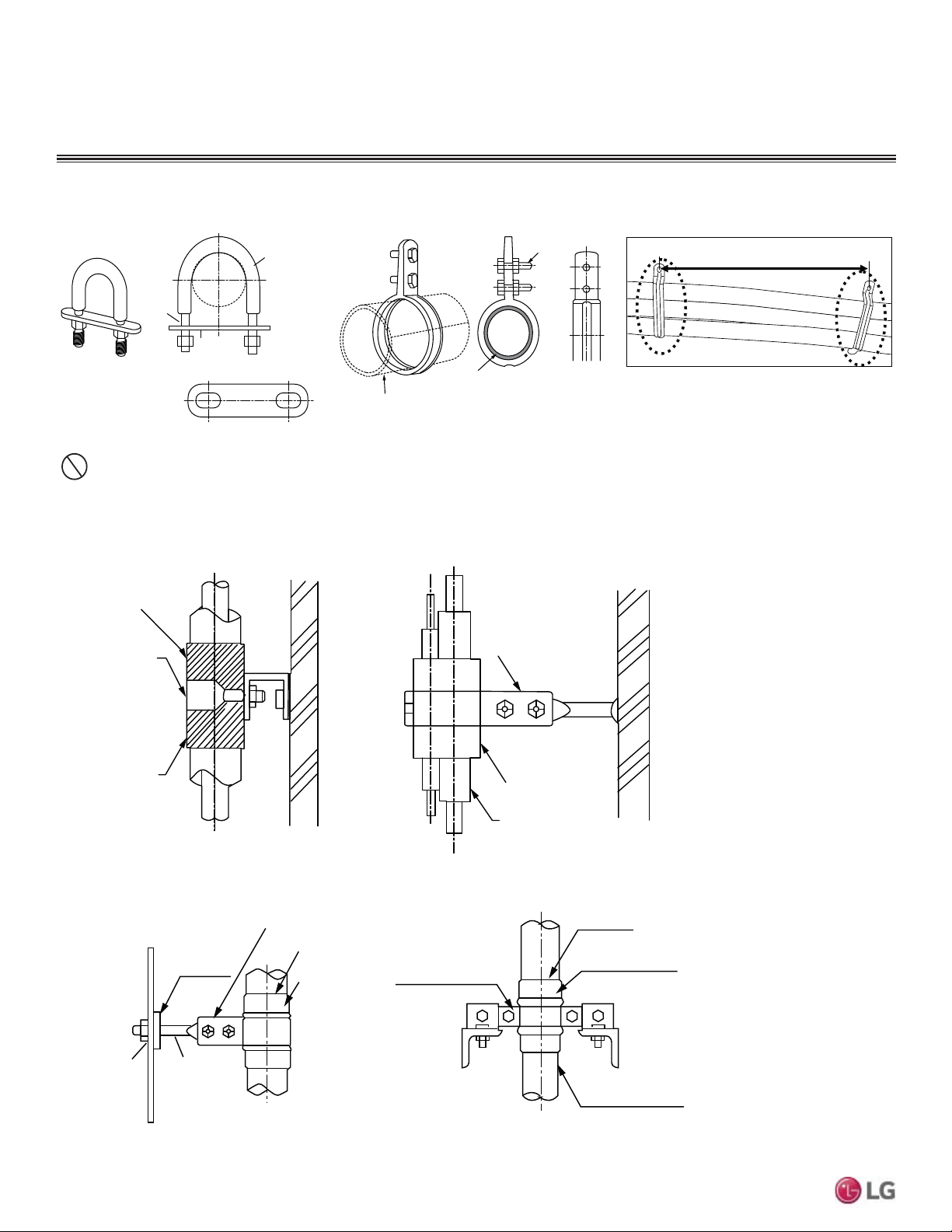
34
MULTI F / MULTI F MAX Outdoor Unit Installation Manual
Due to our policy of continuous product innovation, some specifications may change without notification.
©LG Electronics U.S.A., Inc., Englewood Cliffs, NJ. All rights reserved. “LG” is a registered trademark of LG Corp.
MULTI
F
MAX
MULTI
F
Examples of Supports
Bolt
1.5t
Plate
Insulation
Bolt
PVC
PVC
Figure 34: U-Bolt Support with Insulation. Figure 35: O-Ring Support with Insulation.
To prevent
insulation from
pressing and
lagging, use a cover.
Sheathing
Sheathing
O-Ring
Band
Lags
Do not compress the insulation with the saddle-type support. If the insulation is compressed, it may tear open and allow condensation to
generate during product operation.
Welding
Refrigerant Pipe
Insulated
Support Band
Insulated
Support Band
Down
Stop
Welding
Plate Nut
Hexagonal Nut
O-ring Ba nd
Support at Intervals Between 5 and 6-3/4 Feet
Figure 36: Saddle-Type Support.
Figure 37: U-Bolt Support with an Insulated Pipe. Figure 38: O-Ring Band Support with an Insulated Pipe.
Figure 39: One-Point Down-Stop Support (>441 lbs.).
Figure 40: Two-Point Down-Stop Support.
GENERAL INSTALLATION GUIDELINES
Piping Materials and Handling
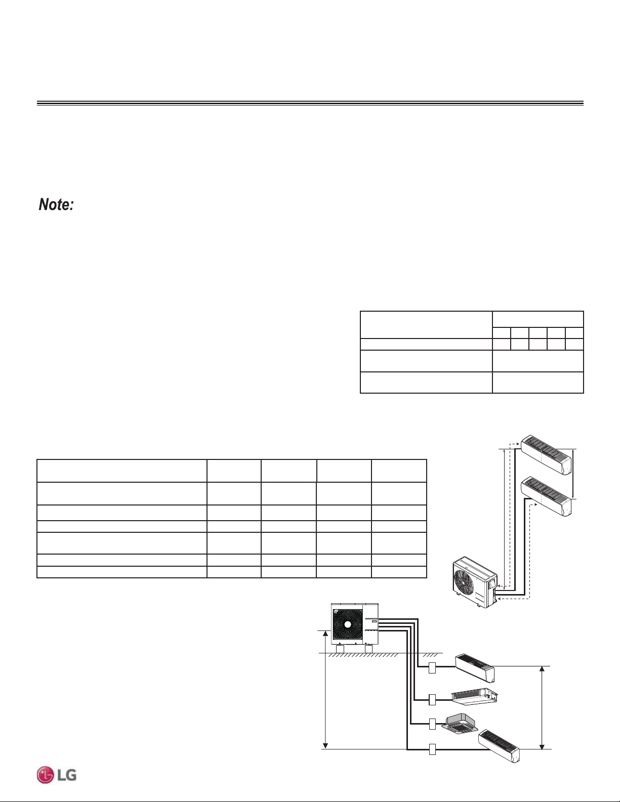
35
Refrigerant Piping Connections
Due to our policy of continuous product innovation, some specifications may change without notification.
©LG Electronics U.S.A., Inc., Englewood Cliffs, NJ. All rights reserved. “LG” is a registered trademark of LG Corp.
MULTI
F
MAX
MULTI
F
h2
h1
A
B
REFRIGERANT PIPING CONNECTIONS
Multi F Outdoor Unit Piping Length and
Elevation Limitations
Piping Length and Elevation Limitations
One of the most critical elements of Multi F and Multi F MAX systems is the refrigerant piping. The tables on the next few pages list pipe
length limits that must be followed in the design of Multi F and Multi F MAX refrigerant pipe systems.
Figure 41: Multi F Refrigerant Piping System
Limitations (LMU18CHV Example).
Outdoor Unit Model (Btu/h)
LMU18CHV /
18,000
LMU24CHV /
24,000
LMU30CHV /
30,000
LMU36CHV /
36,000
Max. Total System Piping Length (ft.)
164
A+B
246.1
A+B+C
246.1
A+B+C+D
246.1
A+B+C+D
Min. Length for One Branch (ft.) 9.8 9.8 9.8 9.8
Max. Length for One Branch (ft.) 82 82 82 82
Max. Elevation Between Each Indoor Unit
and Outdoor Unit (h1)
49.2 49.2 49.2 49.2
Max. Elevation Between Indoor Units (h2) 24.6 24.6 24.6 24.6
Max. Combination of Indoor Units 24,000 33,000 40,000 48,000
Table 19: Multi F Refrigerant Piping System Limitations.
7KHIROORZLQJDUHH[DPSOHVRIPDQXDOSLSHVL]HFDOFXODWLRQV'HVLJQHUVDUHKLJKO\HQFRXUDJHGWRXVH/$76IRU0XOWL)V\VWHPV
Max. 49.2 feet
Max. 24.6 feet
A
B
C
D
Multi F System Example
Example: LMU36CHV outdoor unit with four (4) indoor units
connected.
ODU: Outdoor Unit.
IDU: Indoor Unit.
A, B, C, D: Pipes from Outdoor Unit to Indoor Unit.
Device Connection Limitations
• The minimum number of connected and operating indoor units to Multi F / Multi F MAX systems is two, taking into consideration the
minimum combination ratio.
• The maximum number of indoor units for each Multi F / Multi F MAX heat pump systems is:
LMU18CHV = 2 LMU24CHV = 3 LMU30CHV = 4 LMU36CHV = 4 LMU480HV = 8 LMU540HV = 8 LMU600HV = 8
)RUDOORFDWHGFDSDFLW\LQIRUPDWLRQVHHWKHFRPELQDWLRQWDEOHVLQWKH³0XOWL)0XOWL)0$;&RPELQDWLRQ'DWD0DQXDO´RQZZZOJGIVFRP)RU
SHUIRUPDQFHGDWDVHH³0XOWL)0XOWL)0$;3HUIRUPDQFH'DWD0DQXDO´RQZZZOJGIVFRP
Table 20: Equivalent Piping Length for Elbows, Y-branches,
and Branch Distribution Units.
1
.LWFRQWDLQVWZR<EUDQFKHVRQHIRUOLTXLGDQGRQHIRUYDSRU
Component
Size (Inches)
1/4 3/8 1/2 5/8 3/4
Elbow (ft.) 0.5 0.6 0.7 0.8 1.2
Y-Branch Kit (ft., Multi F MAX
systems only)
1
1.6
Branch Distribution Unit (ft.,
Multi F MAX systems only)
8.2
Using Refrigerant Components
Field-supplied elbows are allowed as long as they are designed for use with
R410A refrigerant. The designer, however, should be cautious with the quantity
and size of fittings used, and must account for the additional pressure losses in
equivalent pipe length calculation for each branch. The equivalent pipe length of
each elbow must be added to each pipe segment.
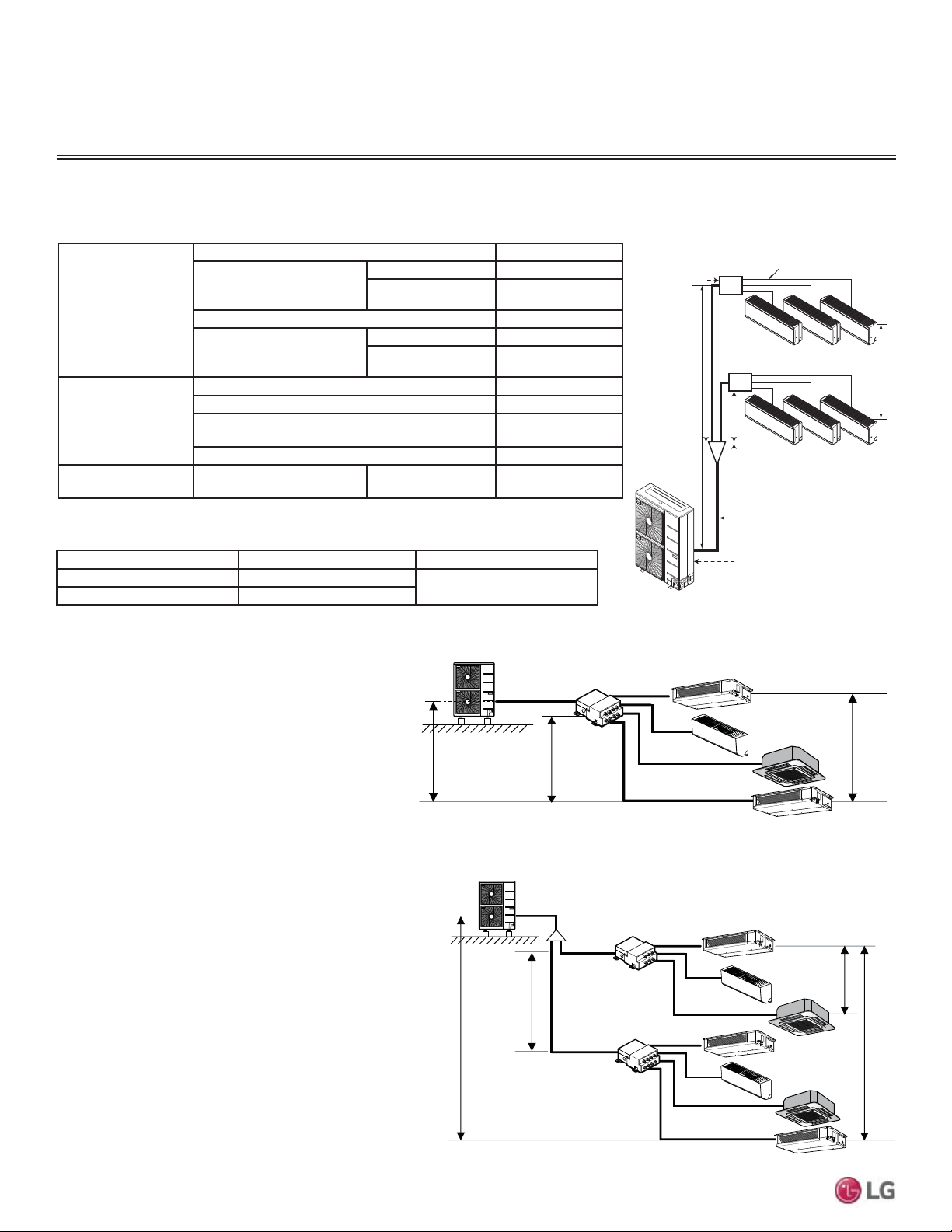
36
MULTI F / MULTI F MAX Outdoor Unit Installation Manual
Due to our policy of continuous product innovation, some specifications may change without notification.
©LG Electronics U.S.A., Inc., Englewood Cliffs, NJ. All rights reserved. “LG” is a registered trademark of LG Corp.
MULTI
F
MAX
MULTI
F
7KHIROORZLQJDUHH[DPSOHVRIPDQXDOSLSHVL]HFDOFXODWLRQV'HVLJQHUVDUHKLJKO\HQFRXUDJHGWRXVH/$76IRU0XOWL)V\VWHPV
Example: LMU540HV outdoor unit with seven (7)
indoor units, and two (2) branch distribution units
connected.
ODU: Outdoor Unit.
IDU: Indoor Unit.
BD: Branch Distribution Unit(s).
Ȉ$0DLQ3LSH
Ȉ%%UDQFK3LSH%UDQFK'LVWULEXWLRQ8QLW>V@WR,QGRRU8QLW>V@
B
A
h2 ≤ 49.2 feet
A
h3 ≤ 32.8 feet
h4 ≤ 49.2 feet
h1 ≤ 98.4 feet
BDU Y-Branch
BDU
IDU
A
ODU
IDU
IDU
IDU
IDU
IDU
IDU
B
B
B
B
B
B
Pipe Length
(ELF = Equivalent
Length of pipe in
Feet)
7RWDOSLSLQJOHQJWKȉ$ȉ% IHHW
Main pipe (Outdoor Unit to
Branch Distribution Units:
ȉ$
Minimum 9.8 feet
Maximum IHHW
7RWDOEUDQFKSLSLQJOHQJWKȉ% IHHW
Branch pipe (Branch
Distribution Units to Indoor
Units: B)
Minimum 10 feet
Maximum IHHW
Elevation Differential
(All Elevation
Limitations are
Measured in Actual
Feet)
If outdoor unit is above or below indoor unit (h1) IHHW
Between the farthest two indoor units (h2) IHHW
Between branch distribution unit and farthest
connected indoor unit(s) (h3)
IHHW
Between branch distribution units (h4) IHHW
Max. Combination of
IDUs
LMU480HV = 65,000 LMU540HV = 73,000 LMU600HV = 81,000
Piping Main Pipe A (inch) Branch Pipe B
Liquid Ø3/8
Depends on the size
of the indoor unit piping
Gas Ø3/4
Example: LMU540HV outdoor unit with four (4)
indoor units, and one (1) branch distribution unit
connected.
ODU: Outdoor Unit.
IDU: Indoor Unit.
BDU: Branch Distribution Unit.
A: Main Pipe.
%%UDQFK3LSH%UDQFK'LVWULEXWLRQ8QLWWR,QGRRU8QLW>V@
A
h2 ≤ 49.2 feet
h3 ≤ 32.8 feet
h1 ≤ 98.4 feet
BDU
ODU
IDU
IDU
IDU
IDU
B
B
B
B
Multi F MAX System Example with One Branch Distribution Unit
Multi F MAX System Example with Two Branch Distribution Units
Multi F MAX Outdoor Unit Piping Length and Elevation Limitations
Table 22: Multi F MAX Refrigerant Piping System Limitations.
h1
C
Branch Pipe
Main Pipe
BD Unit
BD Unit
A
B
h2
Figure 42: Multi F MAX Refrigerant Piping
System Limitations.
Table 23: Multi F MAX Piping Sizes.
REFRIGERANT PIPING CONNECTIONS
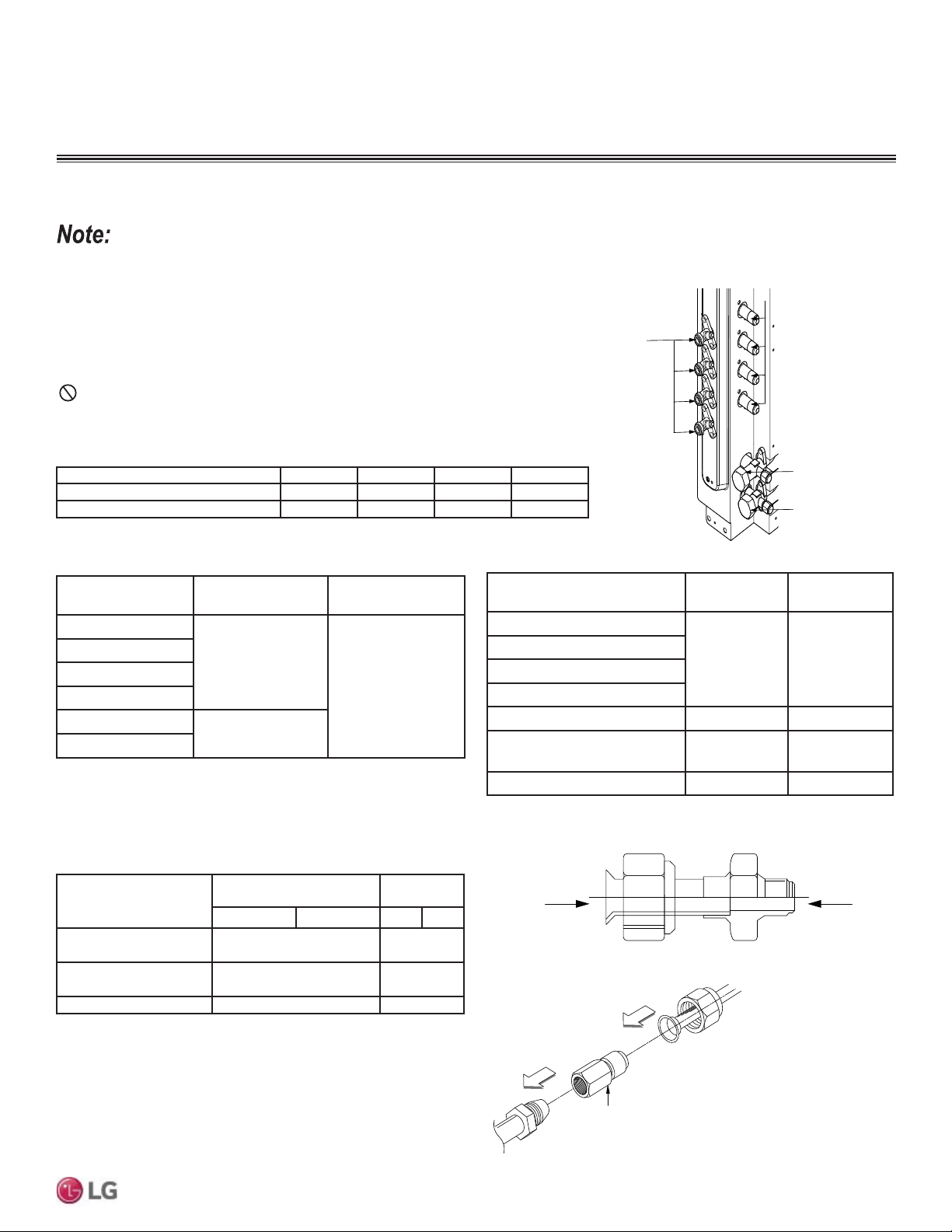
37
Refrigerant Piping Connections
Due to our policy of continuous product innovation, some specifications may change without notification.
©LG Electronics U.S.A., Inc., Englewood Cliffs, NJ. All rights reserved. “LG” is a registered trademark of LG Corp.
MULTI
F
MAX
MULTI
F
Table 24: Outdoor Unit Piping Connections.
Figure 43: Multi F Refrigerant Pipe Connections
(LMU36CHV shown as example).
Avoid Pipe Damage
• When routing field-provided piping, avoid damaging the outdoor unit from
H[FHVVLYHYLEUDWLRQ
• Properly insulate the liquid and gas lines separately up to the point of
connection at the unit frame.
• See table below for Multi F outdoor unit connection types.
Main gas
valve
Main liquid
valve
Gas Piping Connections
Liquid
Piping
Connections
A-UNIT
B-UNIT
C-UNIT
D-UNIT
Connection sockets (included as a factory-supplied accessory with
the indoor units) may need to be used when piping the indoor units
to the outdoor unit.
Indoor Unit Capacity
Vapor (in., OD)
Liquid (in.,
OD)
A B A B
18,000 Btu/h: Wall-
Mounted
ĺĺ
Ø5/8
ĺ
18,000 Btu/h: Low Static
Duct, Four-Way Cassette
ĺ N/A
24,000 Btu/h ĺ N/A
A
B
Flare
to
Indoor
Unit
Flare
to
Outdoor
Unit
1. Align the center of the piping sections and tighten the flare nut by
hand.
2. Tighten the flare nut with a torque wrench, using the arrows on
the wrench as a guide, until a click is heard.
REFRIGERANT PIPING CONNECTIONS
Multi F Outdoor Unit to Indoor Unit Piping Connections
Outdoor Unit Piping Connections LMU18CHV LMU24CHV LMU30CHV LMU36CHV
Liquid Line Connection (in., OD) x Qty. 1/4 x 2 1/4 x 3 1/4 x 4 1/4 x 4
Vapor Line Connection (in., OD) x Qty. 3/8 x 2 3/8 x 3 3/8 x 4 3/8 x 4
Table 25: Indoor Unit Pipe Sizes.
Table 26: Connection Socket Dimensions.
Figure 44: Connection Socket Diagram.
Using the Connection Socket
Connection Socket
(Factory-supplied with
the indoor unit)
Figure 45: Performing Connections.
Indoor Unit Capacity
Vapor Line
Piping Size (in., OD)
Liquid Line
Piping Size (in., OD)
7,000 Btu/h
Ø3/8
Ø1/4
9,000 Btu/h
12,000 Btu/h
15,000 Btu/h
18,000 Btu/h
Ø1/2
24,000 Btu/h
Table 27: Indoor Unit Piping Connections.
Indoor Unit Capacity
Vapor Line
Conn. (in., OD)
Liquid Line
Conn. (in., OD)
7,000 Btu/h
Ø3/8 Ø1/4
9,000 Btu/h
12,000 Btu/h
15,000 Btu/h
18,000 Btu/h: Wall-Mounted Ø5/8 Ø3/8
18,000 Btu/h: Low Static Duct,
Four-Way Cassette
Ø1/2 Ø1/4
24,000 Btu/h Ø1/2 Ø1/4
Correctly route the piping so it does not make contact with mounting bolts.
$OORZURRPIRU¿HOGLQVWDOODWLRQ
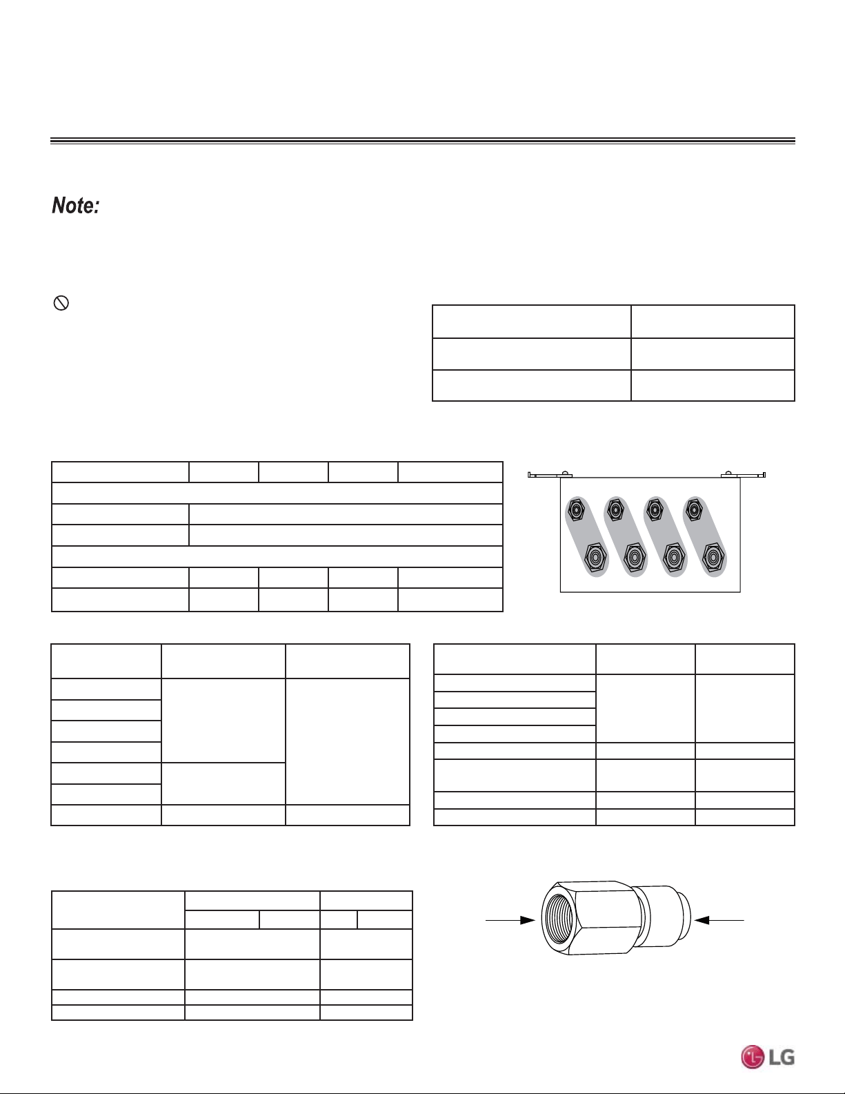
38
MULTI F / MULTI F MAX Outdoor Unit Installation Manual
Due to our policy of continuous product innovation, some specifications may change without notification.
©LG Electronics U.S.A., Inc., Englewood Cliffs, NJ. All rights reserved. “LG” is a registered trademark of LG Corp.
MULTI
F
MAX
MULTI
F
REFRIGERANT PIPING CONNECTIONS
Multi F MAX Outdoor Unit System Piping Connections
Branch Distribution to Indoor Unit Piping Connections
• Install indoor unit liquid and vapor refrigerant pipes (and connec-
tion wiring) to the appropriate branch distribution ports.
• Clearly note on the indoor unit’s refrigerant piping (liquid, vapor)
which branch distribution port it is connected to (A, B, C, D).
Outdoor Unit Piping Connections
LMU480HV, LMU540HV,
LMU600HV
Liquid Line Connection
(in., OD) x Qty.
3/8 x 1
Vapor Line Connection
(in., OD) x Qty.
3/4 x 1
Avoid Pipe Damage
• :KHQURXWLQJILHOGSURYLGHGSLSLQJDYRLGGDPDJLQJWKHRXWGRRUXQLWIURPH[FHVVLYHYLEUDWLRQ
• Properly insulate the liquid and gas lines separately up to the point of connection at the unit frame.
• See table below for Multi F MAX outdoor unit connection types.
Table 28: Outdoor Unit Piping Connections.
Table 29: Branch Distribution Unit Piping Connections.
Table 30: Indoor Unit Pipe Sizes.
Branch Distribution Unit PMBD3620 PMBD3630 PMBD3640 PMBD3641
Piping Connections to Outdoor Unit
Liquid (in., OD) x Qty. Ø3/8 x 1
Vapor (in., OD) x Qty. Ø3/4 x 1
Piping Connections to Indoor Units
Liquid (in., OD) x Qty. Ø1/4 x 2 Ø1/4 x 3 Ø1/4 x 4 Ø1/4 x 3, Ø3/8 x 1
Vapor (in., OD) x Qty. Ø3/8 x 2 Ø3/8 x 3 Ø3/8 x 4 Ø3/8 x 3, Ø5/8 x 1
Table 31: Indoor Unit Piping Connections.
Connection sockets (included as a factory-supplied accessory with the indoor units) may need to be used when piping the indoor units to the
branch distribution unit.
Indoor Unit Capacity
Vapor (in., OD) Liquid (in., OD)
A B A B
18,000 Btu/h: Wall-
Mounted
ĺĺ
Ø5/8
ĺ
18,000 Btu/h: Low Static
Duct, Four-Way Cassette
ĺ N/A
24,000 Btu/h ĺ N/A
36,000 Btu/h ĺ ĺ
Connection Socket
A
B
Figure 46: Branch Distribution Ports to Indoor Units.
ABC D
Figure 47: Connection Socket Diagram.
Indoor Unit
Capacity
Vapor Line
Piping Size (in., OD)
Liquid Line
Piping Size (in., OD)
7,000 Btu/h
Ø3/8
Ø1/4
9,000 Btu/h
12,000 Btu/h
15,000 Btu/h
18,000 Btu/h
Ø1/2
24,000 Btu/h
36,000 Btu/h Ø5/8 Ø3/8
Table 32: Connection Socket Dimensions.
Indoor Unit Capacity
Vapor Line
Conn. (in., OD)
Liquid Line
Conn. (in., OD)
7,000 Btu/h
Ø3/8 Ø1/4
9,000 Btu/h
12,000 Btu/h
15,000 Btu/h
18,000 Btu/h: Wall-Mounted Ø5/8 Ø3/8
18,000 Btu/h: Low Static Duct,
Four-Way Cassette
Ø1/2 Ø1/4
24,000 Btu/h Ø1/2 Ø1/4
36,000 Btu/h Ø5/8 Ø3/8
Correctly route the piping so it does not make contact with mount-
LQJEROWV$OORZURRPIRU¿HOGLQVWDOODWLRQ
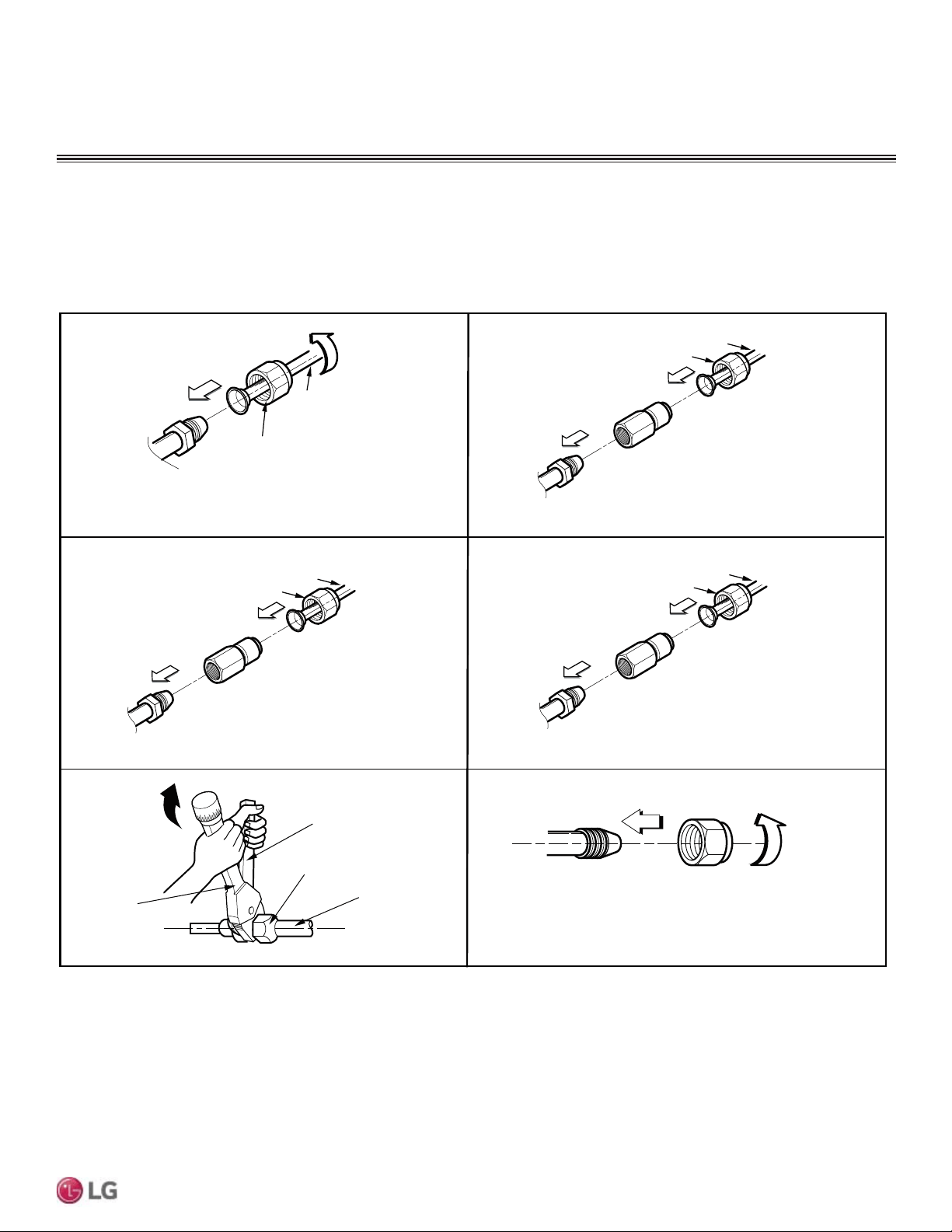
39
Refrigerant Piping Connections
Due to our policy of continuous product innovation, some specifications may change without notification.
©LG Electronics U.S.A., Inc., Englewood Cliffs, NJ. All rights reserved. “LG” is a registered trademark of LG Corp.
MULTI
F
MAX
MULTI
F
Flare nut
Piping
1. 3/8 in. to 3/8 in. Connection
2. 3/8 in. to 1/2 in.
Connection
Flare side to
branch distribution unit or ODU
Flare side to indoor unit
Ø3/8 in.
Flare side to indoor unit or
pipe to indoor unit
Ø1/2 in.
Connection socket
Flare nut
Piping
Ø3/8 in.
Ø3/8 in.
Spanner
Field Piping
Flare nut
Torque
wrench
3. 1/2 in. to 5/8 in.
Connection
Ø5/8 in.
Connection socket
Flare nut
Piping
Ø1/2 in.
4. 1/4 in. to 3/8
Connection
Flare side to indoor unit
Ø3/8 in.
Connection socket
Flare nut
Piping
Ø1/4 in.
Flare
side to
branch distribution unit or ODU
Flare side to indoor unit
Flare
side pipe
from branch distribution unit or ODU
Flare
side to
branch distribution unit or ODU
Multi F MAX Outdoor Unit System Piping Connections, continued.
Figure 48: Possible Outdoor Unit or Branch Distribution Unit to Indoor Unit Connections.
1. Align the center of the piping sections and tighten the flare nut by hand.
2. Tighten the flare nut with a torque wrench, using the arrows on the wrench as a guide, until a click is heard.
3. Wrap insulation around the connection.
REFRIGERANT PIPING CONNECTIONS
Outdoor Unit Condensate Drain Piping
Outdoor unit requires condensate drain piping. Condensate drain pipe is constructed with materials approved by local code. See pages 13 to
17 for information in reference to outdoor unit placement and condensate drainage.
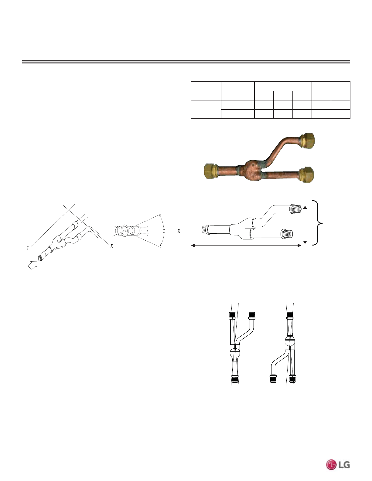
40
MULTI F / MULTI F MAX Outdoor Unit Installation Manual
Due to our policy of continuous product innovation, some specifications may change without notification.
©LG Electronics U.S.A., Inc., Englewood Cliffs, NJ. All rights reserved. “LG” is a registered trademark of LG Corp.
MULTI
F
MAX
MULTI
F
Y-branches may be installed in horizontal or vertical configurations.
When installed vertically, position the Y-branch so the straight-
WKURXJKOHJLVRISOXPE:KHQLQVWDOOHGKRUL]RQWDOO\SRVLWLRQWKH
Y-branch so the take-off leg is level and shares the same horizontal
SODQHDVWKHVWUDLJKWWKURXJKOHJURWDWLRQ
Y-branches should always be installed with the single port facing
the outdoor unit and the two-port end facing the branch distribution
units.
7KHHTXLYDOHQWSLSHOHQJWKRIHDFK<EUDQFKƍPXVWEHDGGHG
to the main pipe segment entered into LATS Multi F piping design
software.
Figure 49: <%UDQFK3RUW,GHQWL¿HU'LDJUDP
Figure 50: +RUL]RQWDO&RQ¿JXUDWLRQ(QG9LHZ
Figure 51: Y-Branch Dimensions Diagram.
Multi F MAX Y-Branch Kit PMBL5620
Table 33: Y-Branch Connection Diameters.
Model
Y-Branch
Type
3RUW,GHQWLÀHULQFK Dimensions
123XY
PMBL5620
Liquid 3/8 3/8 3/8 13.80 3.24
Vapor 3/4 3/4 3/4 12.48 3.02
Figure 52: <EUDQFK,QVWDOODWLRQ$OLJQPHQW6SHFL¿FDWLRQ
Viewed from A in direction of arrow
Horizontal
plane
Within 5°
A
Within 5°
Vertical Up
Configuration
Within ± 3°Within ± 3°
Vertical Down
Configuration
A
B
X
Y
1
2
3
A = To Outdoor Unit B = To Branch Distribution Unit
1
2
3
REFRIGERANT PIPING CONNECTIONS
Y-Branch Kit
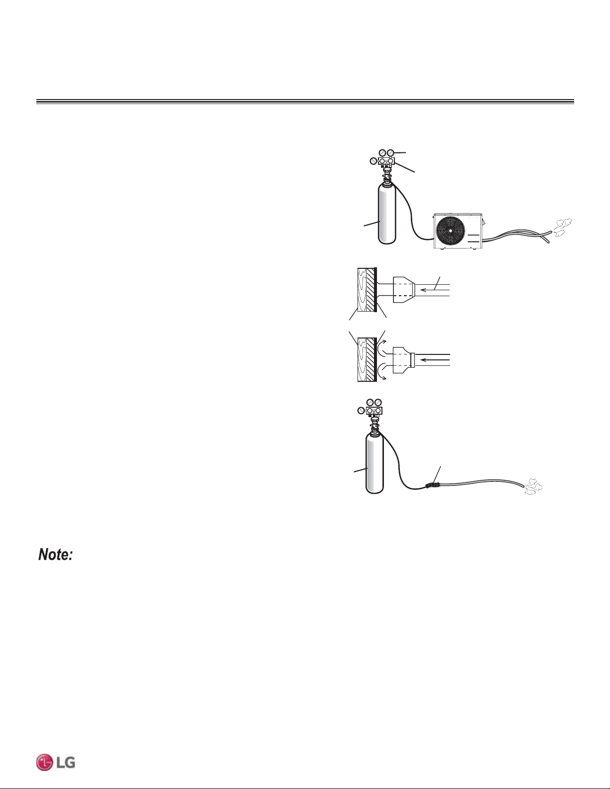
41
Refrigerant Piping Connections
Due to our policy of continuous product innovation, some specifications may change without notification.
©LG Electronics U.S.A., Inc., Englewood Cliffs, NJ. All rights reserved. “LG” is a registered trademark of LG Corp.
MULTI
F
MAX
MULTI
F
Flushing the Refrigerant Piping
Flushing is a method of cleaning the refrigerant piping using pres-
surized nitrogen gas. Flushing:
1. Removes oxidation bubbles that may have formed inside the
copper piping if nitrogen replacement was insufficient during
soldering.
2. Removes foreign material and moisture from piping if the piping
wasn’t stored properly.
3. Checks connections in pipes linking outdoor and indoor units
(both liquid and gas pipes).
72.5 psi
Taping
Primary
Side
Pressure Regulator
Secondary Side (72.5 psi)
Nitrogen
Lo Hi
Nitrogen
Lo Hi
Wood Insulation
Flushing the Refrigerant Piping Procedure
1. Attach a pressure regulator on a nitrogen cylinder.
2. Connect the charge hose from the pressure regulator to the
outdoor unit liquid piping side service port before its connection
to the indoor or BD (Multi F MAX systems only) unit piping.
3. Open the main valve on the nitrogen cylinder and set the pres-
sure regulator to 0.5 MPa (72.5 psi).
4. Verify that the nitrogen is flowing through the piping correctly.
5. When flushing, block the open end of the piping with a wood
insulation block. When the pressure becomes too high, quickly
remove the block.
6. Repeat steps 4 and 5 until the piping is completely flushed and
clean.
7. Connect the charge hose from the pressure regulator to the out-
door unit gas piping side service port before its connection to the
indoor or BD (Multi F MAX systems only) unit piping.
8. Follow steps 3, 4, 5, and 6.
9. For systems with BD unit(s) (Multi F MAX only), each piping run
should be flushed individually before connecting the indoor units
(follow steps 3, 4, 5, and 6).
1LWURJHQÀXVKLQJLVVWURQJO\UHFRPPHQGHGDIWHUVROGHULQJ)RUHLJQPDWHULDOVLQWKHSLSLQJZLOOFDXVHV\VWHPPDOIXQFWLRQ
Figure 53: Flushing the Refrigerant Piping.
Flushing the Refrigerant Piping
REFRIGERANT PIPING PREPARATION
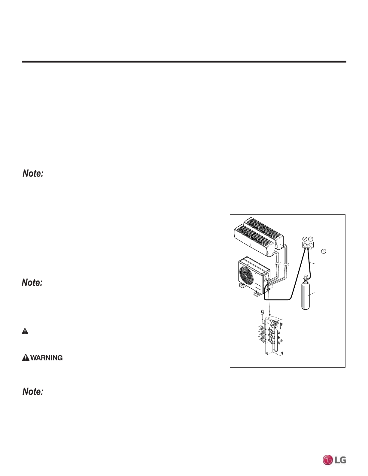
42
MULTI F / MULTI F MAX Outdoor Unit Installation Manual
Due to our policy of continuous product innovation, some specifications may change without notification.
©LG Electronics U.S.A., Inc., Englewood Cliffs, NJ. All rights reserved. “LG” is a registered trademark of LG Corp.
MULTI
F
MAX
MULTI
F
Leak Test and Vacuum Procedures
Before performing the test run, Multi F and Multi F MAX refrigerant piping and the piping connections to the outdoor unit, the indoor units, and
the BD units (Multi F MAX systems only) must be evacuated to remove any non-condensible gases and moisture that may be present in the
system, and checked for leaks. Air and moisture that is left in the piping can lead to undesirable results and can cause damage to the working
unit. It is important to go through a complete air purging cycle to be sure that the lines are cleared out. Note that this process may have to be
repeated should any air or moisture be found to remain in the piping. After air purging and evacuating the lines, be sure to take a leak test for
all piping and tubing. If any air and moisture remain in the refrigerant system:
1. Pressure in the system rises.
2. Operating current rises.
3. Cooling or heating efficiency drops.
4. Moisture in the refrigerant circuit may freeze and block capillary
tubing.
5. Water may corrode parts of the refrigeration system.
Before the Leak Test
1. Check that all refrigerant piping, the drain pipe, and power wiring / communications
cables are properly connected.
2. Remove the caps from both the gas and the liquid service valves on the outdoor
unit. Verify that both service valves are closed.
Pressure Gauge Hookup
3. Connect the manifold valve (which includes the pressure gauges), along with the dry
nitrogen gas cylinder, to the service valves using the charge hoses.
Use a manifold valve for leak testing. The high side manifold valve must always be kept
closed.
Leak Test Procedure
4. Pressurize the system to maximum 550 psig with the dry nitrogen gas.
8VHRIFRPEXVWLEOHJDVHVLQFOXGLQJR[\JHQPD\UHVXOWLQ¿UHRUH[SORVLRQUHVXOWLQJLQ
personal injury or death.
8VHRIFRPEXVWLEOHJDVHVLQFOXGLQJR[\JHQUXQVWKHULVNRI¿UHDQGH[SORVLRQUHVXOWLQJLQ
personal injury or death. Inert gas (nitrogen) should be used when checking leaks, cleaning
or repairs of pipes, etc.
• To avoid nitrogen entering the refrigerant system in a liquid state, the top of the cylinder must be higher than its bottom when the system is
pressurized.
• The cylinder should be used in a vertical standing position.
5. Close the cylinder valve when the gauge reading reaches 550 psig, and then test for leaks using the liquid soap method.
6. While running the nitrogen gas tank hookup, apply a soap water or a liquid neutral detergent to all indoor, BD, outdoor unit connection(s),
and all refrigerant piping joints with a soft brush. Also test for leaks at both of the gas and liquid side service valves.
Perform the leak test by pressurizing nitrogen gas to 550 psi on both the liquid and gas pipes. Test with the piping service valves closed. If the
pressure does not drop for twenty-four (24) hours, the system passes the test. If the pressure drops, there is a nitrogen leak in the system. Find the
leak, repair, and then test again.
Leak Test
DANGER
Figure 54: Leak Test Diagram.
Charge Hose
Nitrogen Gas
Cylinder (with
cylinder upright)
Indoor Units
Outdoor Unit
Lo Hi
Manifold Valve
Pressure
Gauge
Appearances will vary depending on model.
REFRIGERANT PIPING PREPARATION
Leak Test
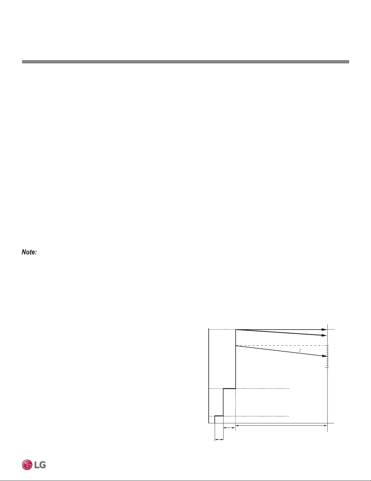
43
Refrigerant Piping Connections
Due to our policy of continuous product innovation, some specifications may change without notification.
©LG Electronics U.S.A., Inc., Englewood Cliffs, NJ. All rights reserved. “LG” is a registered trademark of LG Corp.
MULTI
F
MAX
MULTI
F
Leak Test Procedure, continued.
7. While operating the pressure gauge system, observe the connections for any leaks. If bubbles appear at any of the connections (indoor,
BD, and outdoor units) or refrigerant piping joints, a leak is present.
8. Make a note of where the leaks are, and remove the soap with a clean cloth.
9. Disengage the nitrogen pressure by loosening the charge hose connector at the nitrogen cylinder. After the system pressure is back to
normal range, disconnect hose from the cylinder.
10. Repair the connections and piping where bubbles / leaks were observed. When finished, repeat leak testing using the liquid soap method
and nitrogen cylinder.
11. After system is leak free, depressurize by loosening the charge hose connector at the nitrogen cylinder. When system pressure returns to
normal, disconnect the hose from the cylinder.
Essential Points for Leak Testing
The key to successful testing is strict adherence to the leak testing procedure.
1. The liquid and gas piping in each refrigerant system should be pressurized with nitrogen gas in accordance with the steps listed below.
Step 1: Pressurize to 43.5 psi for three (3) minutes or more. (Will identify if major leaks are present in the system.)
Step 2: Pressurize to 217.6 psi for three (3) minutes or more. (Will identify if major leaks are present in the system.)
Step 3: Pressurize to 551.1 psi for approximate twenty-four (24) hours. (Will identify if minor leaks are present in the system.)
Pressurizing the system to 551.1 psi does not guarantee the identification of minor leaks if the pressure is maintained for only a short time. It
is recommended that the system remain pressurized for at least 24 hours.
Example:
'XULQJ/HDN7HVWSVLDW)
7ZHQW\IRXU+RXUV/DWHUSVLDW)
Although the pressure dropped from 551.1 psi to 543.9 psi, it can
be assumed that there are no leaks because pressure can also drop
due to the change in outdoor temperature.
3 minutes
5 minutes
24 hours
Step 1
Step2
Step 3
(Time)
Outdoor Temperature (°F
3.8 (551.1)
3.75 MPa
(543.9 psi)
3.5 (507.6)
3.0 (435.1)
2.5 (362.6)
2.0 (290.1)
1.5 (217.6)
1.0 (145.0)
0.5 (72.5)
0.0 (0.0)
Step 1: 0.3 MPa (43.5 psi) at 3 minutes
Step 2: 1.5 MPa (217.6 psi) at 5 minutes
Step 3: 3.8 MPa (551.1 psi) at 24 Hours
MPa (psi)
77°F
68°F
59°F
Piping system should not be pressured to more than 551.1 psi. Pressures greater than 551.1 psi may damage the piping system and cause unit
malfunction.
2. Check for pressure drop. If there is no drop in pressure, the test is successful. If the pressure drops, there is a leak in the piping system.
If, however, there was a change in the ambient temperature between when pressure was initialized and when pressure drop is checked,
WKHQFDOFXODWLRQVPXVWEHDGMXVWHGDFFRUGLQJO\$GLIIHUHQFHRI)FDQDFFRXQWIRUDSUHVVXUHFKDQJHRISVL
Compensation Value: Temperature at Pressure Initialization – Temperature at Pressure Check × 1.45
Figure 55: Leak Test Time Diagram.
REFRIGERANT PIPING PREPARATION
Leak Test
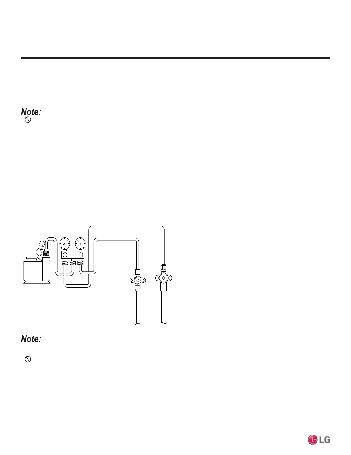
44
MULTI F / MULTI F MAX Outdoor Unit Installation Manual
Due to our policy of continuous product innovation, some specifications may change without notification.
©LG Electronics U.S.A., Inc., Englewood Cliffs, NJ. All rights reserved. “LG” is a registered trademark of LG Corp.
MULTI
F
MAX
MULTI
F
REFRIGERANT PIPING PREPARATION
Vacuum Procedure
Vacuum drying should be performed from the service port provided on the outdoor unit’s service valve to the vacuum pump commonly used
for liquid pipe and the vapor pipe. Vacuum of the pipe and the indoor units should be made from the port of the outdoor unit’s service valve
with the service valve closed.
•
Never perform air purging using refrigerant; it will damage the outdoor unit.
• Use a vacuum pump that can evacuate to 500 microns.
1. Evacuate the system from the liquid and vapor pipes with a vacuum pump for over two (2) hours and bring the system to 500 microns.
2. Maintain system under that condition for over one (1) hour; if the vacuum gauge rises, the system may contain moisture or a leak.
3. If there is a possibility of moisture in the piping (rainwater may have entered the piping if work was performed during a rainy season or
over an extended period), then:
• Evacuate the system for two (2) hours to 7.3 psi (vacuum break) with nitrogen gas.
• Evacuate it again with the vacuum pump for one (1) hour to 500 microns (vacuum drying).
4. If the system cannot be evacuated to 500 microns, repeat the steps of vacuum break and drying.
5. Finally, after maintaining the system in vacuum for one (1) hour, check if the vacuum gauge rises or not.
• If the primary refrigerant charge is not performed in a reasonable time after the vacuum procedure is complete, wet air may infiltrate the
RXWGRRUXQLW,IZHWDLULVPL[HGZLWKUHIULJHUDQWWKHUHIULJHUDQWF\FOHPD\PDOIXQFWLRQDQGWKHXQLWPD\EHGDPDJHG
• Do not perform refrigerant charge while the compressor is operating, otherwise, liquid may leak and subsequently damage the com-
pressor.
• Use a micron gauge to measure vacuum.
• Obtain the precise amount of refrigerant needed using calculations outlined in the following pages. Too much or too little refrigerant may
cause the system to malfunction.
• ,IRWKHUUHIULJHUDQWVDUHPL[HGLQWKHRULJLQDOUHIULJHUDQWWKHUHIULJHUDQWSLSLQJV\VWHPPD\EHGDPDJHGRUPDOIXQFWLRQ
• %HFDXVH5$LVDPL[HGUHIULJHUDQWWKHUHTXLUHGDGGLWLRQDOUHIULJHUDQWPXVWEHFKDUJHGLQLWVOLTXLGVWDWH,IWKHUHIULJHUDQWLVFKDUJHGLQ
its gaseous state, its composition changes and the system will not work properly.
Vacuum Pump
Liquide Pipe
Vapor Pipe
Figure 56: Vacuum Procedure Diagram.
Vacuum Procedure
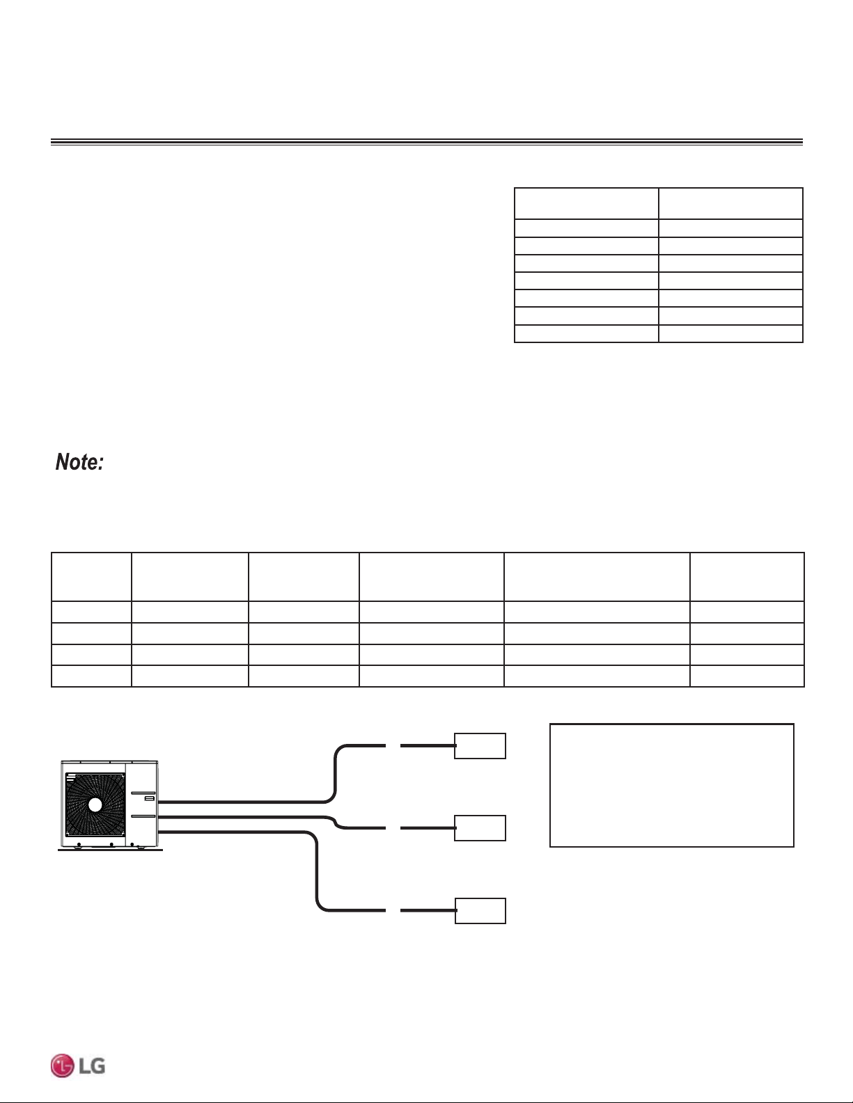
45
Refrigerant Piping Connections
Due to our policy of continuous product innovation, some specifications may change without notification.
©LG Electronics U.S.A., Inc., Englewood Cliffs, NJ. All rights reserved. “LG” is a registered trademark of LG Corp.
MULTI
F
MAX
MULTI
F
Refrigerant Charge
LG Multi F and Multi F MAX outdoor units ship from the factory with a charge of
R410A refrigerant. A trim charge may need to be added to take into account
additional piping length.
To determine the additional refrigerant that is needed, apply the formulas below,
and record the results. If the total additional refrigerant charge value is a negative
number, then an additional trim charge does not need to be added to the system.
$GGLWLRQDOFKDUJHOEV ,QVWDOOHG/HQJWKRI%UDQFK>$@±&KDUJHOHVV3LSH/HQJWK>/@[D
,QVWDOOHG/HQJWKRI%UDQFK>%@±&KDUJHOHVV3LSH/HQJWK>/@[D
,QVWDOOHG/HQJWKRI%UDQFK>&@±&KDUJHOHVV3LSH/HQJWK>/@[D
,QVWDOOHG/HQJWKRI%UDQFK>'@±&KDUJHOHVV3LSH/HQJWK>/@[D
- CF (Correction Factor) x 5.29
Outdoor
Unit Model
Min. to Max. Piping
Length for One
Branch (ft.)
Max. Total System
Piping Length (ft.)
Chargeless Pipe Length
per Branch (L) (ft.)
Piping Length (No Additional
Refrigerant [ft])
Additional Charge
Needed (a) (oz./ft.)
LMU18CHV 9.8 to 82 164 24.6 49.2 0.22
LMU24CHV 9.8 to 82 246.1 24.6 73.8 0.22
LMU30CHV 9.8 to 82 246.1 24.6 98.4 0.22
LMU36CHV 9.8 to 82 246.1 24.6 98.4 0.22
Outdoor Unit
Factory Charge
lbs. of R410A
LMU18CHV 3.96
LMU24CHV 3.96
LMU30CHV 6.18
LMU36CHV 6.18
LMU480HV 9.7
LMU540HV 9.7
LMU600HV 12.3
Table 34: Outdoor Unit Factory Charge.
Multi F Systems
• Number of installed length of branches depends on the specifications of the outdoor unit model.
• &) 0D[LPXPQXPEHURIFRQQHFWLEOHLQGRRUXQLWV±7RWDOQXPEHURIFRQQHFWHGLQGRRUXQLWV
Table 35: 0XOWL)2XWGRRU8QLW3LSLQJ6SHFL¿FDWLRQV
Figure 57: Multi F Additional Refrigerant Charge Example.
Each branch pipe
A = 82 ft.
B = 16 ft.
C = 49 ft.
Additional Charge
A
B
C
9,000
9,000
9,000
Example: LMU36CHV
= (82 - 24.6) x 0.22
+ (16 - 24.6) x 0.22
+ (49 - 24.6) x 0.22
- (4 - 3) x 5.29
= 10.82 oz.
REFRIGERANT PIPING PREPARATION
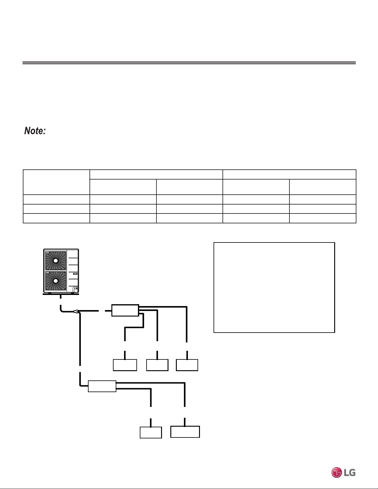
46
MULTI F / MULTI F MAX Outdoor Unit Installation Manual
Due to our policy of continuous product innovation, some specifications may change without notification.
©LG Electronics U.S.A., Inc., Englewood Cliffs, NJ. All rights reserved. “LG” is a registered trademark of LG Corp.
MULTI
F
MAX
MULTI
F
Refrigerant Charge
Multi F MAX Systems
Outdoor Unit Model
Main Piping Length Branch Piping Length
Chargeless Pipe Length
of Main Pipe (L) (ft.)
Additional Charge
Needed (a) (oz./ft.)
Chargeless Pipe Length
per Branch Pipe (B) (ft.)
Additional Charge
Needed (b) (oz./ft.)
LMU480HV 16.4 0.54 16.4 0.22
LMU540HV 16.4 0.54 16.4 0.22
LMU600HV 16.4 0.54 16.4 0.22
Table 36: 0XOWL)0$;2XWGRRU8QLW3LSLQJ6SHFL¿FDWLRQV
$GGLWLRQDOFKDUJHOEV 7RWDO0DLQ3LSLQJ/HQJWK>$@&KDUJHOHVV3LSH/HQJWKRI0DLQ3LSH>/@[D
,QVWDOOHG/HQJWKRI%UDQFK>%@±&KDUJHOHVV3LSH/HQJWK>%@[E
,QVWDOOHG/HQJWKRI%UDQFK>%@±&KDUJHOHVV3LSH/HQJWK>%@[E
,QVWDOOHG/HQJWKRI%UDQFK>%@±&KDUJHOHVV3LSH/HQJWK>%@[E
- CF (Correction Factor) x 3.53
• Number of installed length of branches depends on system specifications.
• &) 0D[LPXPQXPEHURIFRQQHFWLEOHLQGRRUXQLWV±7RWDOQXPEHURIFRQQHFWHGLQGRRUXQLWV
Figure 58: Multi F MAX Additional Refrigerant Charge Example.
B3
18,000 9,000 9,000
LMU540HV
• Total main pipe (A) = 60 ft.
• Each branch pipe
B1 =
B2 =
B3 =
B4 =
B5 =
Additional Charge
= (60 - 16.4) x 0.54
+ (49 - 16.4) x 0.22
+ (17 - 16.4) x 0.22
+ (17 - 16.4) x 0.22
+ (10 - 16.4) x 0.22
+ (23 - 16.4) x 0.22
– (8 - 5) x 3.53
= 20.43 oz.
A
49 ft.
17 ft.
17 ft.
10 ft.
23 ft.
BD Unit
BD Unit
9,000 18,000
A
A
B1 B2
B4 B5
REFRIGERANT PIPING PREPARATION
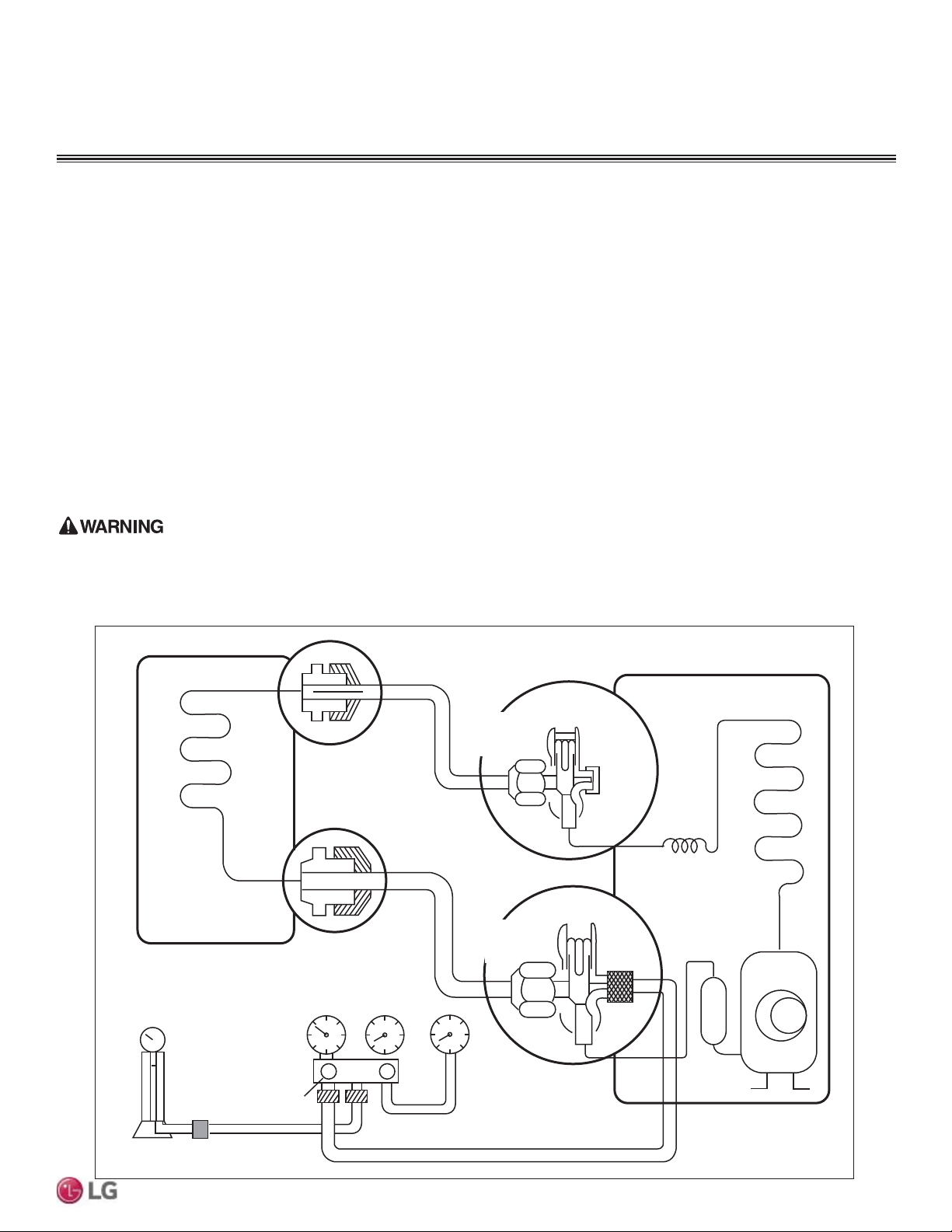
47
Refrigerant Piping Connections
Due to our policy of continuous product innovation, some specifications may change without notification.
©LG Electronics U.S.A., Inc., Englewood Cliffs, NJ. All rights reserved. “LG” is a registered trademark of LG Corp.
MULTI
F
MAX
MULTI
F
Charging the Refrigerant
1. Determine the refrigerant that is needed, applying the necessary formulas as outlined in the previous pages.
2. Connect the charging cylinder to the charge hose on the manifold valve.
3. Purge air from the charge hose by opening the valve at the bottom of the cylinder, and press the check valve on the manifold valve.
4. Confirm that the “Lo” knob of the manifold valve is open and charge the system with liquid refrigerant. (Because R-410A is a non-azeo-
trope refrigerant, it must be charged in the liquid state.)
• If the required amount of refrigerant cannot be charged all at once, the refrigerant can be charged a little at a time (approximately 5.29
ounces) while the system operates in cooling. This procedure must be repeated until the entire amount of refrigerant gets charged into
WKHV\VWHPSHUIRUPRQFHWKHQZDLWDSSUR[LPDWHO\RQH>@PLQXWHEHIRUHUHVXPLQJ
5. Immediately disconnect the charge hose from the service port on the three-way valve. Stopping halfway allows the refrigerant to
discharge.
• If the system has been charged with liquid refrigerant while it operates, turn the system off before disconnecting the hose.
6. Mount the valve stem nuts and the service port nut. Use torque wrench to tighten the service port nut to a torque of 1.8 kg.m and check
for leaks.
:KHQLQVWDOOLQJRUUHORFDWLQJWKHRXWGRRUXQLWPDNHVXUHWKDWQRVXEVWDQFHRWKHUWKDQWKHVSHFL¿HGUHIULJHUDQW5$HQWHUVWKHUHIULJHUDQW
FLUFXLW$Q\SUHVHQFHVRIIRUHLJQVXEVWDQFHVVXFKDVDLUFDQFDXVHDQDEQRUPDOSUHVVXUHULVHDQGPD\UHVXOWLQH[SORVLRQDQGSK\VLFDOLQMXU\
Lo
Refrigerant
Cylinder
Outdoor Unit
Indoor Unit
Liquid Piping
Gas Piping
Open
Three-Way
Valve
Three-Way
Valve
OPEN
Open
Check Valve
(One)
Vacuum
Gauge
Figure 59: Charging the Refrigerant.
Refrigerant Charge
REFRIGERANT PIPING PREPARATION
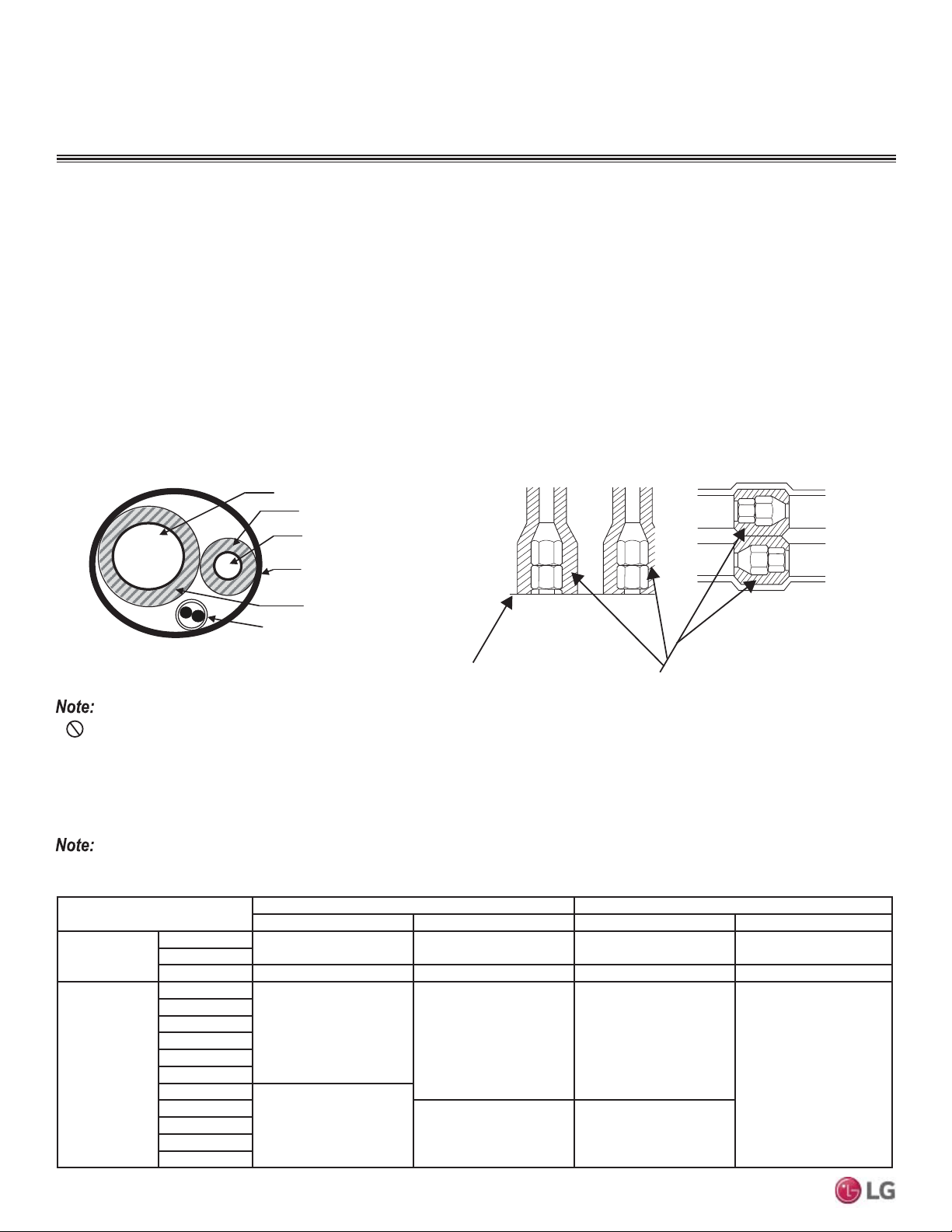
48
MULTI F / MULTI F MAX Outdoor Unit Installation Manual
Due to our policy of continuous product innovation, some specifications may change without notification.
©LG Electronics U.S.A., Inc., Englewood Cliffs, NJ. All rights reserved. “LG” is a registered trademark of LG Corp.
MULTI
F
MAX
MULTI
F
Surface of
Indoor Unit Casing
Field-Provided
Pipe Insulation
Figure 60: Typical Pipe Insulation, Power Wire and
Communications Cable Arrangement
Figure 61: Typical Insulation Butt-
Joint at Indoor Unit Casing
Figure 62: Typical Refrigerant
Flare Fitting Insulation Detail
•
Do not insulate gas and liquid pipes together as this
FDQUHVXOWLQSLSHOHDNDJHDQGPDOIXQFWLRQGXHWRH[WUHPH
temperature fluctuations.
• Be sure to fully insulate the piping connections.
Refrigerant Piping System Insulation
All refrigerant piping from the outdoor unit to the indoor units / BD units (Multi F MAX systems only) must be insulated correctly for safety and
usage. Y-branch connections, refrigerant piping, field-provided isolation ball valves (if present), service valves, and elbows must be properly
and completely insulated using closed cell pipe insulation (up to the indoor unit piping connections). To prevent heat loss / heat gain through
the refrigerant piping, all refrigerant piping including liquid lines and vapor lines shall be insulated separately. Insulation shall be a minimum
ƎWKLFNDQGWKLFNQHVVPD\QHHGWREHLQFUHDVHGEDVHGRQDPELHQWFRQGLWLRQVDQGORFDOFRGHV7DEOHEHORZOLVWVPLQLPXPZDOOWKLFNQHVV
requirements for Ethylene Propylene Diene Methylene (EPDM) insulation.
,QVLGHWKHRXWGRRUXQLWPD[LPXPSLSHWHPSHUDWXUHLV)DQGPLQLPXPSLSHWHPSHUDWXUHLV))RUILHOGLQVXODWLRQRIUHIULJHUDQWSLSLQJ
between outdoor units and indoor units, consider the following pipe temperature ranges for an operating heat pump system:
• +HDWLQJPRGHUHIULJHUDQWWHPSHUDWXUHUDQJHV/LTXLG)+LJK3UHVVXUH9DSRU)
• &RROLQJPRGHUHIULJHUDQWWHPSHUDWXUHUDQJHV/LTXLG)/RZ3UHVVXUH9DSRU)
Vapor Line
Liquid Line
Min. 18 Gauge
Cable
Power/Communication
Pi
p
e Sleeve
Insulation Material
Insulation
Material
Refrigerant Piping Insulation
Minimum Refrigerant Pipe Ethylene Propylene Diene Methylene (EPDM) Insulation Wall Thickness Requirements
Follow locals codes when selecting EPDM insulation wall thickness.
&ODVVLÀFDWLRQ
Air-conditioned location Non-air conditioned location
1. Typical location 2. Special location 3. Typical location 4. Special location
Liquid pipe
ø1/4 inch
1/2 inch 1/2 inch 1/2 inch 1/2 inch
ø3/8 inch
¡LQFK 1/2 inch 1/2 inch 1/2 inch 1/2 inch
Vapor pipe
ø3/8 inch
1/2 inch
3/4 inch 3/4 inch
1 inch
ø1/2 inch
ø5/8 inch
ø3/4 inch
ø7/8 inch
ø1 inch
ø1-1/8 inches
3/4 inch
ø1-1/4 inches
1 inch 1 inch
ø1-3/8 inches
ø1-1/2 inches
ø1-3/4 inches
Table 37: Insulation Guidelines for Typical and Special Circumstances
REFRIGERANT PIPING PREPARATION
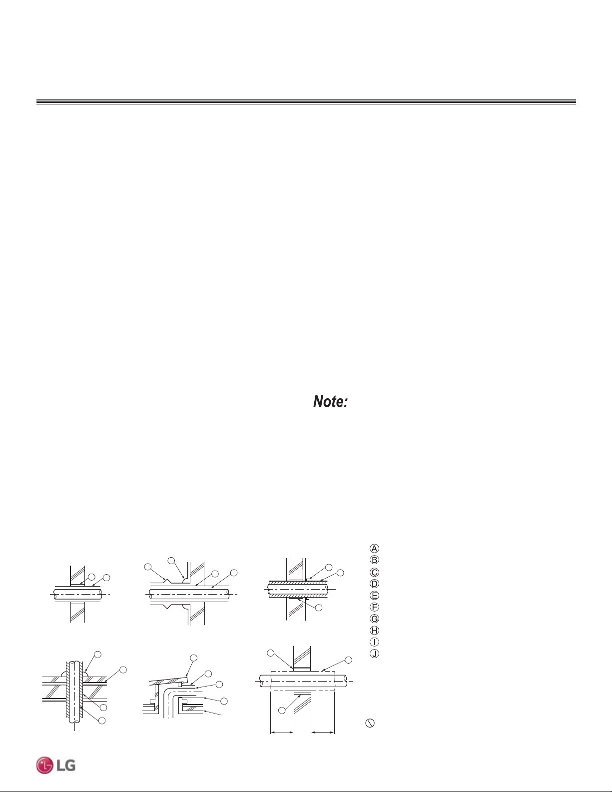
49
Refrigerant Piping Connections
Due to our policy of continuous product innovation, some specifications may change without notification.
©LG Electronics U.S.A., Inc., Englewood Cliffs, NJ. All rights reserved. “LG” is a registered trademark of LG Corp.
MULTI
F
MAX
MULTI
F
1. Typical location (Air-conditioned location): When the piping passes through an indoor area where the indoor unit operates.
• Apartment, classroom, office, mall, hospital, etc.
2. Special location (Air-conditioned location):
1. When the location is air conditioned, but there is severe temperature/humidity difference due to high ceilings
• Church, auditorium, theater, lobby, etc.
2. When the location is air conditioned, but internal temperature/humidity are high
• Bathroom, swimming pool, locker room, etc.
3. Typical location (Non-Air conditioned location): When the piping passes through an indoor area where the indoor unit
does not operate.
• Hallway or a dormitory or school, etc.
4. Special location (Non-Air conditioned location): If conditions 1 and 2 below are present.
1. When the piping passes through an indoor area where the indoor unit does not operate.
2. When the humidity is high and there is no air flow in the location where the piping is installed.
• The thickness of the above insulation material is based on heat conductivity of 0.61 Btu/in/h/ft
2
)
Refrigerant Piping Insulation
40 in40 in
A
B
D
F
G
B
G
D
B
H
I
J
A
E
B
I
A
B
D
C
Inside wall (concealed)
Floor (fire-resistance)
Area between fire-resistant
insulation and boundary wall
Roof pipe shaft
Outside wall
Outside wall (exposed)
Sleeve
Insulation
Lagging
Caulk
Band
Water-resistant layer
Sleeve with edge
Lagging
Mortar or other fire-resistant caulk
Fire-resistant insulation
When filling an access hole with mortar, cover the
area with steel plate so that the insulation will not
fall through. For this area, use fire-resistant
materials for both the insulation and cover.
Vinyl cover should not be used.
Pipe Sleeves at Penetrations
LG requires that all pipe penetrations through walls, floors, and
pipes buried underground be routed through a properly insulated
sleeve that is sufficiently sized to provide free movement of the pipe
and does not compress the insulation. Underground refrigerant pipe
shall be routed inside a protective sleeve to prevent insulation dete-
rioration. Also follow federal, state, and local regulations and codes
when choosing a sleeve type.
Figure 63: Pipe Sleeve Options.
For example:
Diameter of Gas Piping: 1/2"
Diameter of Liquid Piping: 1/4"
Thickness of Gas Piping Insulation: 0.4" x 2
Thickness of Liquid Piping Insulation: 0.4" x 2
Surplus: 0.8"
Sleeve diameter (total): 3.1" minimum
Diameter of penetrations shall be determined by pipe diameter
plus the thickness of the insulation.
REFRIGERANT PIPING PREPARATION
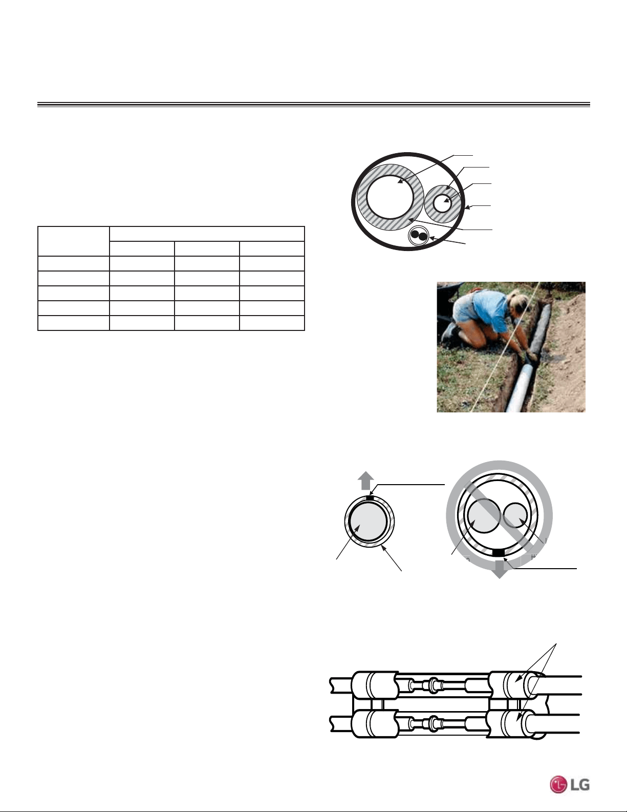
50
MULTI F / MULTI F MAX Outdoor Unit Installation Manual
Due to our policy of continuous product innovation, some specifications may change without notification.
©LG Electronics U.S.A., Inc., Englewood Cliffs, NJ. All rights reserved. “LG” is a registered trademark of LG Corp.
MULTI
F
MAX
MULTI
F
Underground Refrigerant Piping
Refrigerant pipe installed underground should be routed inside a
vapor tight protective sleeve to prevent insulation deterioration and
water infiltration. Refrigerant pipe installed inside underground
casing must be continuous without any joints. Underground refriger-
ant pipe must be located at a level below the frost line.
Figure 64: Typical Arrangement of Refrigerant Pipe and Cable(s) in a
Utility Conduit.
Table 38: Utility Conduit Sizes.
1
OD pipe diameter in inches; Values in parenthesis () indicate OD of pipe with insulation jacket.
2
Diameter of pipe with insulation. Thickness of pipe insulation is typical. Actual required thickness may vary based
RQVXUURXQGLQJDPELHQWFRQGLWLRQVDQGVKRXOGEHFDOFXODWHGDQGVSHFL¿HGE\WKHGHVLJQHQJLQHHU
3
Insulation thickness (value in parenthesis) = 3/8 inch.
4
Insulation thickness (value in parenthesis) = 1 inch.
5
Insulation thickness (value in parenthesis) = 3/4 inch.
Figure 65: Underground Refrigerant Piping.
Liquid Pipe
1
Vapor Pipe
1
1/2 (2.0
2,5
) 5/8 (2-1/8
2,5
) 3/4 (2-1/4
2,5
)
1/4 (1.0)
3
444
3/8 (1-1/8)
3
445
1/2 (1-1/2)
4
555
5/8 (1-5/8)
4
555
3/4 (1-3/4)
4
555
Vapor Line
Liquid Line
Min. 18 Gauge
Cable
Power/Communication
Pi
p
e Sleeve
Insulation Material
Insulation
Material
Refrigerant Piping Insulation
Insulation material
Figure 66: Correct Cutting Line Placement.
Installing the Insulation
1. Insulation material should be longer than the refrigerant piping.
Each vapor and liquid piping must be insulated separately.
2. Place the closed-cell ethylene propylene diene methylene
(EPDM) insulation material carefully around each refrigerant pipe
so as not to damage it. Be sure the insulation material cutting line
is place upward.
3. Apply adhesive to both cut surfaces of the insulation and press
together. Allow adhesive to dry so that the bond is secure and
does not come apart.
Figure 67: Piping with Insulation Material.
Gas or Liquid
Pipe (Insulated
Separately)
Liquid Pipe
Cutting Line
Cutting Line
Correct
Incorrect
Insulation
Gas Pipe
L
Cutti
pe
Insulating Piping Joints
1. Push the EPDM insulation from the straight piping surrounding
the joint (elbow, outdoor unit to indoor unit piping connection
point, etc.) as close together as possible.
2. Cut a piece of insulation to fit the joint, overlapping the insulation
on the surrounding piping by at least one (1) inch.
3. Apply adhesive to bond all the ends.
4. Secure by completely wrapping narrow vinyl tape around the
insulation / joint so that there are no gaps.
5. Tape should be sufficient to cover the piping so it can fit into the
rear piping housing area at the back of the indoor unit or BD unit
(Multi F MAX systems only).
REFRIGERANT PIPING PREPARATION
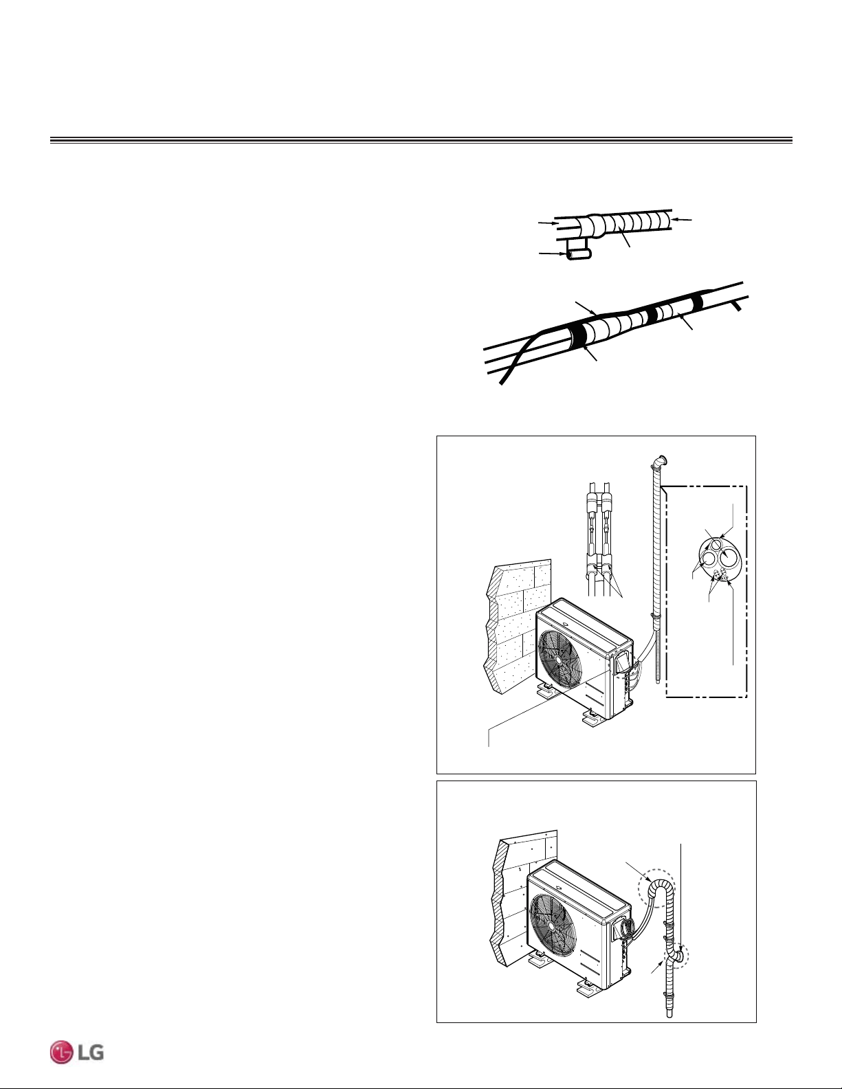
51
Refrigerant Piping Connections
Due to our policy of continuous product innovation, some specifications may change without notification.
©LG Electronics U.S.A., Inc., Englewood Cliffs, NJ. All rights reserved. “LG” is a registered trademark of LG Corp.
MULTI
F
MAX
MULTI
F
Special Applications
If an additional drain hose is necessary, the end of drain outlet
should be routed above the ground. Secure and the drain hose
appropriately.
When the Outdoor Unit is Installed Below the Indoor Unit:
1. Wrap the vinyl tape around the separately insulated refrigerant
piping, the drain hose, and the communications cable / power
wiring together from the bottom to top.
2. Secure the bundle along the outside wall using saddles or a simi-
lar type of piping support.
3. Seal any openings in the wall.
• A trap is required to prevent water from entering
the outdoor unit electrical control box.
Plastic
Band
Insulation and Tape
Drain Hose
Piping
Connecting
Cables
Power Supply
Cord
Seal the small opening
around the piping.
Seal the small opening
around the piping.
Trap
Trap
Outdoor Unit Below Indoor Units
Outdoor Unit Above Indoor Units
Figure 68: Bundling the Connection Components (From Outdoor Unit to
,QGRRU8QLW%'8QLW>0XOWL)0$;V\VWHPV@
Vinyl tape (narrow)
Connection pipe
Connecting cable
Vinyl tape (wide)
Wrap with vinyl tape
Indoor unit pipe
Pipe
When the Outdoor Unit is Installed Above the Indoor Unit:
1. Wrap the vinyl tape around the separately insulated refrigerant
piping, the drain hose, and the communications cable / power
wiring together from the bottom to top.
2. Secure a portion of the bundle along the outside wall using sad-
dles or a similar type of piping support.
3. At the appropriate location, form a trap with the bundle to prevent
water from entering interior spaces or the electrical control box of
the outdoor unit
.
4. Secure the rest of the bundle along the outside wall using sad-
dles or a similar type of piping support.
5. Seal any openings in the wall.
Figure 69: Special Applications.
Bundling
If a conduit is not used on the connection from the outdoor unit to
the interior, bundle both insulated refrigerant pipes, the drain hose,
and outdoor unit to indoor unit / BD unit communication cable /
power wiring together with wide vinyl tape.
Refrigerant Piping Insulation
REFRIGERANT PIPING PREPARATION
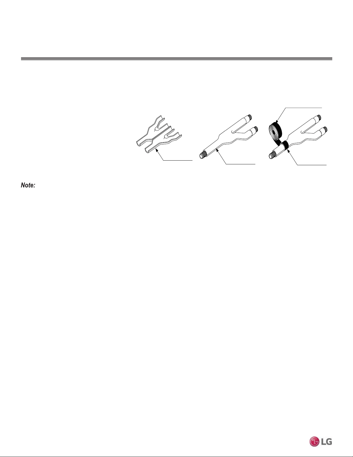
52
MULTI F / MULTI F MAX Outdoor Unit Installation Manual
Due to our policy of continuous product innovation, some specifications may change without notification.
©LG Electronics U.S.A., Inc., Englewood Cliffs, NJ. All rights reserved. “LG” is a registered trademark of LG Corp.
MULTI
F
MAX
MULTI
F
Y-Branch Kit Insulation
Each Y-branch kit comes with clam-shell type peel-and-stick insulation jackets molded to fit the Y-branch fittings—one for the liquid line, one
for the vapor line.
• Check the fit of the Y-branch clam-shell
insulation jacket after the Y-branch is
installed.
• Mark the pipe where the insulation jacket
ends.
• Remove the jacket.
• Install field-provided insulation on the pipes
first.
• Peel the adhesive glue protector slip and
install the clam-shell jacket over the fitting
Liquid and Gas
Pipe Joints
Y-Branch Kit Insulation
Insulation for
Field-Installed Piping
Field-Supplied Insulation Tape
Figure 70: Y-branch Insulation Detail.
Additional Insulation for Y-Branches May be Required in Humid Environments.
,IWKHV\VWHPKDVEHHQRSHUDWLQJIRUDORQJWLPHLQDKLJKKXPLGLW\HQYLURQPHQWGHZSRLQWWHPSHUDWXUHPRUHWKDQ)FRQGHQVDWHLVOLNHO\
to form. If this happens, install 3/8 inch thick ethylene propylene diene methylene (EPDM) insulation that is plenum-rated with a heat-resistance
factor that follows applicable local, state, and federal codes.
Refrigerant Piping Insulation
REFRIGERANT PIPING PREPARATION
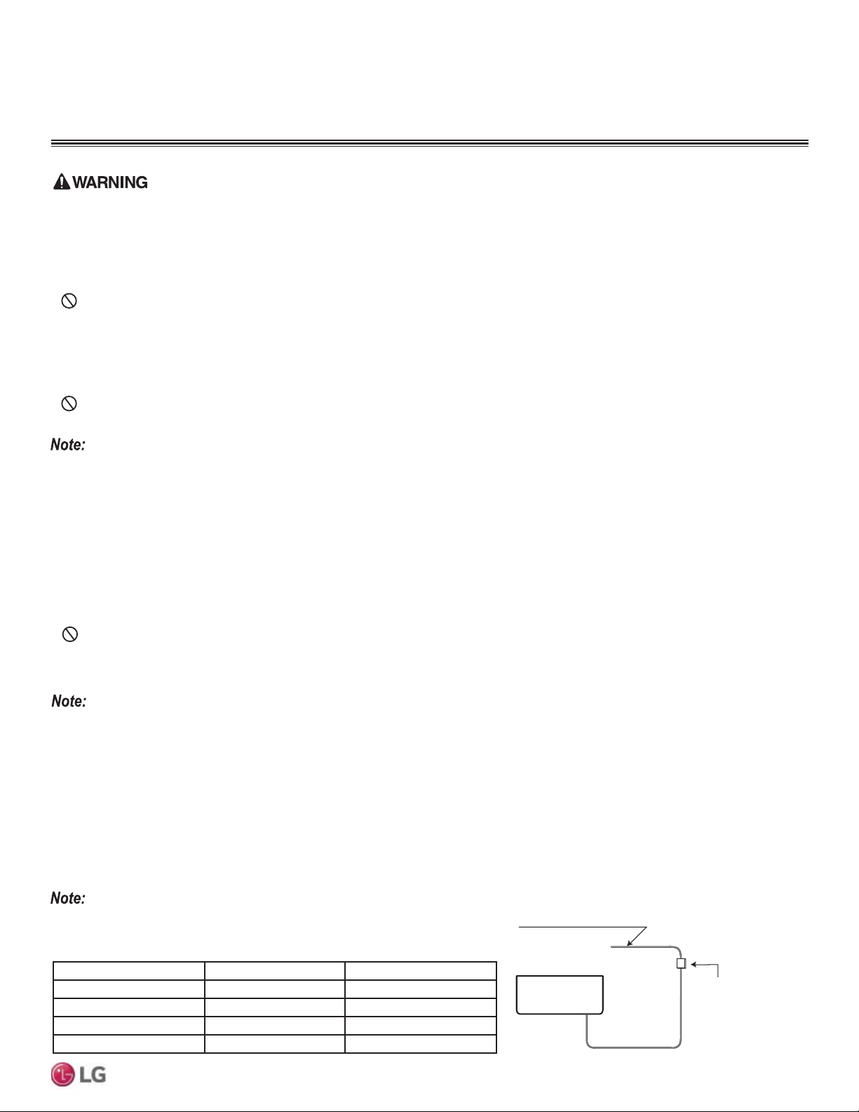
53
Wiring
Due to our policy of continuous product innovation, some specifications may change without notification.
©LG Electronics U.S.A., Inc., Englewood Cliffs, NJ. All rights reserved. “LG” is a registered trademark of LG Corp.
MULTI
F
MAX
MULTI
F
• All power wiring and communication cable installation must be performed by authorized service providers working in accordance with local,
state, and National Electrical Code regulations related to electrical equipment and wiring, and following the instructions in this manual.
• Be sure that main power to the unit is completely off before proceeding. Follow all safety and warning information outlined at the beginning
of this manual. Failure to do so may cause electric shock and bodily injury.
• Familiarize yourself with the location of the circuit breaker. Be sure that a circuit breaker or some other emergency power cutoff device is in
place before any power wiring is done to the system. Failure to do so may cause bodily injury or death.
•
Never touch any power lines or live cables before all power is cutoff to the system. To do so, may cause bodily injury or death.
• Undersized wiring may lead to unacceptable voltage at the unit and may become a fire hazard, causing bodily injury or death
• 3URSHUO\JURXQGWKHRXWGRRUXQLWV*URXQGZLULQJLVUHTXLUHGWRSUHYHQWDFFLGHQWDOHOHFWULFDOVKRFNGXULQJFXUUHQWOHDNDJH
• Install appropriately sized breakers / fuses / overcurrent protection switches and wiring in accordance with local, state, and National Electri-
cal Code regulations related to electrical equipment and wiring, and following the instructions in this manual. Using an oversized breaker or
fuse may result in electric shock, physical injury or death.
•
Do not connect ground wire to refrigerant, gas, or water piping; to lightning rods; to telephone ground wiring; or to the building plumb-
ing system. Failure to properly provide a National Electrical Code-approved earth ground can result in electric shock, physical injury or death.
3RZHU6XSSO\3RZHU:LULQJ6SHFLILFDWLRQV
• Multi F and Multi F MAX systems operate at 1Ø, 208-230V, 60Hz.
• 3RZHUVXSSO\ZLUHW\SHDQGVL]HVKRXOGEHVHOHFWHGEDVHGRQ1DWLRQDO(OHFWULFDO&RGHDQGORFDOFRGHV0D[LPXPDOORZDEOHYROWDJHIOXFWX-
ation ±10% or nameplate rated value.
• Properly ground the outdoor units per National Electrical Code and local codes.
• For power to the outdoor units, use field-supplied copper wiring that is solid or stranded, and shielded with the wires separately insulated.
• *URXQGZLUHVKRXOGEHORQJHUWKDQWKHFRPPRQSRZHUFRPPXQLFDWLRQZLUHV
• Connect the wiring firmly so the wires cannot be easily pulled out.
• Refer to the inside of the chassis cover for circuit and terminal block diagrams for your model unit.
• Always match color codes of each wire and follow wiring diagram.
• Outdoor unit wiring can be found on the inside of the outdoor unit control cover.
• Consider ambient conditions (temperature, direct sunlight, inclement weather, etc.) when selecting, installing, and connecting the power wiring.
• Properly ground the outdoor units. Improperly ground wire can cause communication problems from electrical noise and motor current
leakage. *URXQGZLULQJPXVWDOZD\VEHLQVWDOOHGE\DTXDOL¿HGWHFKQLFLDQ
• If the system operates in reversed phase, it may damage the compressors and other components.
• If there is a possibility of reversed phase, phase loss, momentary blackout, or the power goes on and off while the system is
operating, install a field-supplied phase loss protection circuit.
• Undersized wiring may lead to unacceptable voltage at the unit and may cause unit malfunction.
• Install appropriately sized breakers / fuses / overcurrent protection switches and wiring in accordance with local, state, and National Electri-
cal Code regulations related to electrical equipment and wiring, and following the instructions in this manual. Using an oversized breaker or
fuse may result in equipment malfunction and property damage.
•
Do not connect ground wire to refrigerant, gas, or water piping; to lightning rods; to telephone ground wiring; or to the building plumbing
system. Failure to properly provide a National Electrical Code-approved earth ground can result in property damage and equipment malfunction.
WIRING
General Information
Air
Conditioner
Main Power Source
Circuit Breaker
Use a circuit breaker
or time delay fuse
Figure 71: Circuit Breaker
It is highly recommended to provide a circuit breaker between the power source and
the outdoor unit as shown.
Outdoor Unit Model Power Source Fuse or Breaker Capacity
LMU18CHV, LMU24CHV 1Ø, 208-230V 20A
LMU30CHV, LMU36CHV 1Ø, 208-230V 25A
LMU480HV, LMU540HV 1Ø,208-230V 40A
LMU600HV 1Ø,208-230V 45A
Table 39: Circuit Breaker / Fuse Size.
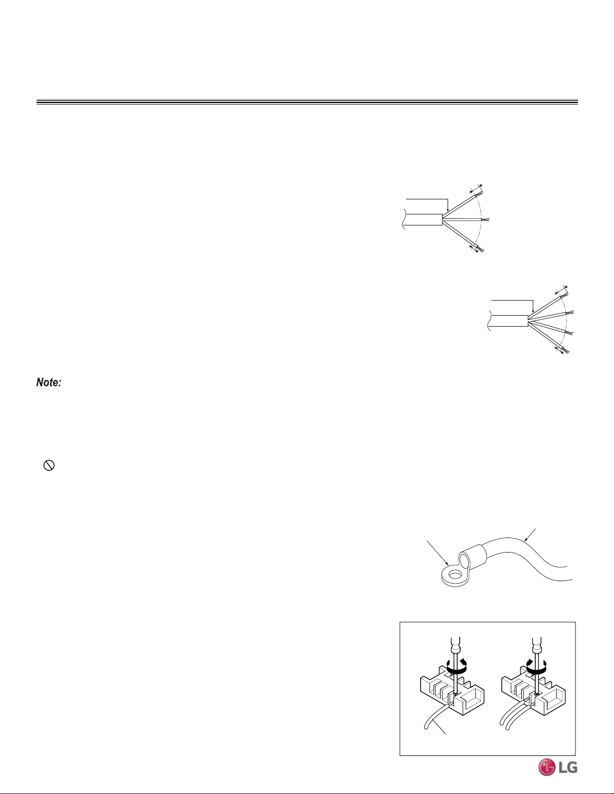
54
MULTI F / MULTI F MAX Outdoor Unit Installation Manual
Due to our policy of continuous product innovation, some specifications may change without notification.
©LG Electronics U.S.A., Inc., Englewood Cliffs, NJ. All rights reserved. “LG” is a registered trademark of LG Corp.
MULTI
F
MAX
MULTI
F
Figure 72: Multi F / Multi F MAX Outdoor and
Indoor / Branch Distribution Unit Wiring and
Communications Cable Diagram.
Ring Terminal
Power Wiring
Outdoor Unit Wiring Connection Guidelines
Best practice dictates using ring or spade terminals to terminate power wiring at the power
terminal block
To Install a Ring Terminal:
1. Trim the strand wiring with wire cutters or pliers, then strip the insulation to expose the
strand wiring to about 3/8 inch.
2. Using a ring terminal fastener or pliers, securely clamp a ring terminal to each stripped
wire end.
Figure 73: Close up of a Typical Ring Terminal
6/16” ± 2/16”
13/16”
GN/YL
Power Wiring, Ground
to Outdoor Unit
Power Wiring, Ground,
Communication Cable
From Outdoor Unit
To Indoor Unit or from the
Outdoor Unit to the Branch
Distribution Unit
13/16”
GN/YL
GN/YL = (Ground, Yellow)
6/16” ± 2/16”
WIRING
General Information
Connecting Cable
Connecting cable
Loosening the
terminal block
screw
Fastening the
wiring tightly
• Multi F Systems: All power wiring / communication cable to be minimum 18 AWG from the
outdoor unit to the indoor unit, stranded, shielded or unshielded (if shielded, it must be
grounded to the chassis of the outdoor unit only), and must comply with applicable local
and national codes.
• Multi F MAX Systems: All power wiring / communication cable to be minimum 16 AWG
from the outdoor unit to the BD unit, and 18 AWG from the BD unit to the indoor unit,
stranded, shielded or unshielded (if shielded, it must be grounded to the chassis of the
outdoor unit only), and must comply with applicable local and national codes.
• For power / communication wires between the Multi F and Multi F MAX outdoor units and
the indoor units / BD units (Multi F MAX systems only), use a four (4) conductor, strand-
ed, shielded or unshielded wire. If shielded, the wire must be grounded to the chassis at
the outdoor unit only.
• Insulation material as required by local code.
• 5DWHGIRUFRQWLQXRXVH[SRVXUHRIWHPSHUDWXUHVXSWR)
• Firmly attach the cable; provide slack but secure in a way to prevent
external forces from being imparted on the terminal block.
• Wiring should be completed without splices.
• Always verify the communication cable is connected to a communications terminal. Never apply line voltage power to the communication
cable connection. If contact is made, the PCBs may be damaged.
• The shield of the communications cable connecting the outdoor unit to the indoor units should be grounded only to the outdoor unit frame.
• Tie the shield of each cable segment together using a wire nut at the indoor unit. Maintain polarity throughout the communication network.
• Position the incoming power to the outdoor unit away from the power / communications cables from the outdoor unit to the indoor unit /
branch distribution unit (Multi F MAX systems only).
•
Never use a common multiple-core communications cable. Each communications bus shall be provided a separate cable (i.e., between
outdoor unit and indoor unit).
To Connect the Wiring to the Terminals:
1. Remove the terminal screws from the (outdoor unit, BD unit, or indoor unit) terminal plate
with a screwdriver.
2. Position the ring terminal around the terminal, place the terminal screw in the ring, and
tighten to the terminal plate using a screwdriver.
Figure 74: Tightening the Ring Terminal to the
Terminal Plate.
General Communication Cable Specifications
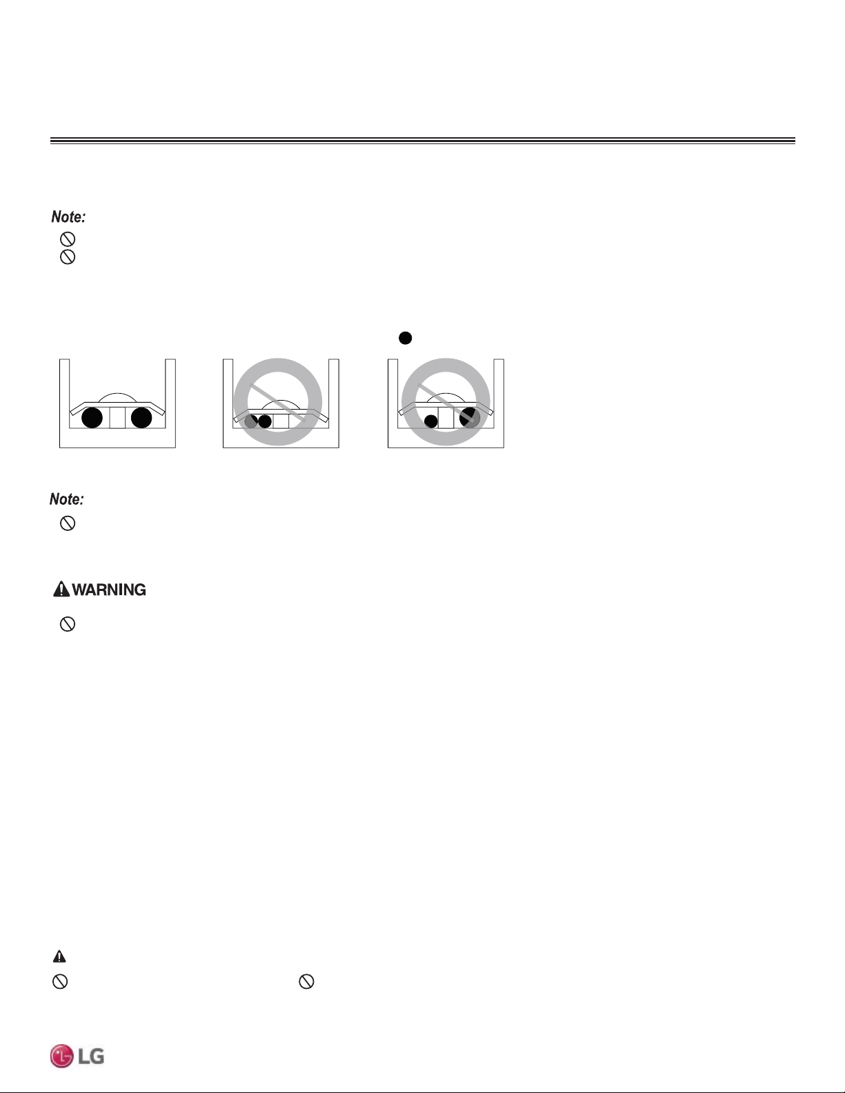
55
Wiring
Due to our policy of continuous product innovation, some specifications may change without notification.
©LG Electronics U.S.A., Inc., Englewood Cliffs, NJ. All rights reserved. “LG” is a registered trademark of LG Corp.
MULTI
F
MAX
MULTI
F
If ring terminals or spade clips are not available, then:
• Do not terminate different gauge wires to the power terminal block. Slack in the wiring may generate heat and fire.
•
Do not over tighten the connections; overtightening may damage the terminals.
• When terminating wires of the same thickness, follow the instructions demonstrated in the illustrations below.
• )LUPO\DWWDFKWKHZLUHVHFXUHLQDZD\WRSUHYHQWH[WHUQDOIRUFHVIURPEHLQJLPSDUWHGRQWKHWHUPLQDOEORFN
• Use an appropriately sized screwdriver for tightening the terminals.
• If power wires are not properly terminated and firmly attached, there is risk of fire, electric shock, and physical injury or death.
• Never ground the shield of the communications cable to the indoor unit frame or other grounded entities of the building. Failure to
properly provide a National Electrical Code-approved earth ground can result in electric shock, physical injury or death.
• Never apply line voltage power to the communications cable terminal block. If contact is made, the PCBs may be damaged.
• Always include some allowance in the wiring length when terminating. Provide some slack to facilitate removing the electrical panels while
servicing.
:Copper Wire
Terminate multiple power wires of
the same gauge to both sides.
Do not terminate two wires on
one side.
Do not terminate different gauge
wires to a terminal block.
Figure 75: Proper and Improper Power Wiring Connections
WIRING
Power Wiring and Communications Cable Connections
&RQQHFWLQJWKH3RZHU:LULQJ&RPPXQLFDWLRQV&DEOHWRWKH2XWGRRU8QLW
1. Detach the outdoor unit control cover by loosening and removing the screws.
2. Remove the side panel and the conduit panel knockouts.
3. Draw the power wiring to the outdoor unit, and the power wiring / communications cable (connecting cable) to the indoor units or BD unit
(Multi F MAX systems only), through field-supplied conduits. Ensure there is enough length to connect the wiring / cables to the terminals
on the outdoor unit. Secure the conduit to the outdoor unit using a field-supplied lock nut on the interior of the outdoor unit frame.
4. Properly connect the power wiring, and the power wiring / communications cable (connecting cable) to the correct terminals. Refer to the
outdoor unit wiring
diagram.
5. To provide strain relief, (separately) secure the power wiring and the power wiring / communications cable (connecting cable) to the out-
door unit with the factory-supplied clamps (up to 35 lbs.). Zip ties can also be used to hold all wiring / cables in place.
6. Re-attach the outdoor unit cover control to the original position with the screws.
Do not use damaged or loose power wiring. 'RQRWPRGLI\RUH[WHQGWKHRXWGRRUXQLW¶VSRZHUZLULQJUDQGRPO\(QVXUHWKDWWKHSRZHU
ZLULQJZLOOQRWEHSXOOHGQRUZHLJKWEHSODFHGRQWKHSRZHUZLULQJGXULQJRSHUDWLRQ7KHUHLVULVNRI¿UHHOHFWULFVKRFNDQGSK\VLFDOLQMXU\RUGHDWK
DANGER
Outdoor Unit Wiring Connection Guidelines, continued.
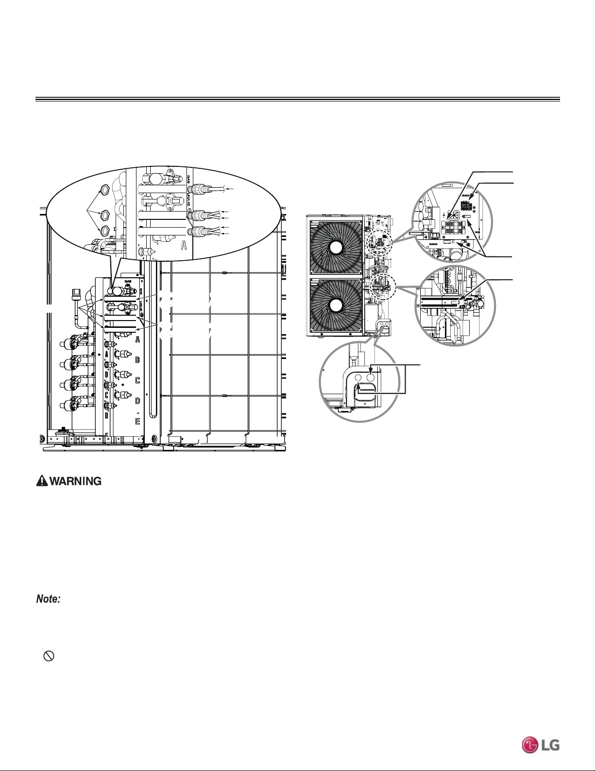
56
MULTI F / MULTI F MAX Outdoor Unit Installation Manual
Due to our policy of continuous product innovation, some specifications may change without notification.
©LG Electronics U.S.A., Inc., Englewood Cliffs, NJ. All rights reserved. “LG” is a registered trademark of LG Corp.
MULTI
F
MAX
MULTI
F
• The communications cable (connecting cable) from the outdoor unit to the indoor unit should be isolated from the electrical wiring of
H[WHUQDOGHYLFHVVXFKDVFRPSXWHUVHOHYDWRUVUDGLRDQGWHOHYLVLRQEURDGFDVWLQJIDFLOLWLHVDQGPHGLFDOLPDJLQJRIILFHV&RPPXQLFDWLRQ
problems can arise from electrical noise.
•
Do not install the power wiring to the outdoor unit and the power wiring / communications cable (connecting cable) to the indoor
units in the same conduit. These wiring / cables should have separate conduits that are placed a reasonable distance apart. Communi-
cation problems can arise from electrical noise.
• Secure all field wiring connections with appropriate wire strain relief. Improperly securing wires will create undue stress on equipment
power lugs. Inadequate connections may generate heat, cause a fire and physical injury or death.
• 3URSHUO\WLJKWHQDOOSRZHUOXJV/RRVHZLULQJPD\RYHUKHDWDWFRQQHFWLRQSRLQWVFDXVLQJDILUHSK\VLFDOLQMXU\RUGHDWK
• 5HSODFHDOOFRQWUROER[DQGSDQHOFRYHUV,IFRYHUSDQHOVDUHQRWLQVWDOOHGVHFXUHO\GXVWZDWHUDQGDQLPDOVPD\HQWHUWKHRXWGRRUXQLW
causing fire, electric shock, and physical injury or death.
Connecting the Power Wiring / Communications Cable to the Outdoor Unit, continued.
Figure 76: Connecting the Power Wiring / Communications Cables to
the Outdoor Unit (LMU18~36CHV; LMU480, 540HV).
Power supply cabl
(1Ø, 208/230V)
Power Supply Cable
(1Ø, 208/230V)
Connecting cabl
(1Ø, 208/230V)
Connecting Cable
(1Ø, 208/230V)
Lock nut
(Field Supplied)
Indoor Unit A
Conduit
(Field Supplied)
Indoor Unit B
Indoor Unit C
Indoor Unit D
Conduit
Hole
WIRING
Power Wiring and Communications Cable Connections
Figure 77: Connecting the Power Wiring / Communications Cables to
the Outdoor Unit (LMU600HV).
Power Wiring
Terminal
Connecting
Cable Terminal
Cord Clamp
Cord Clamp
* Make sure the rubber bushes are
properly used in knock-out holes after
connecting the main power wiring.
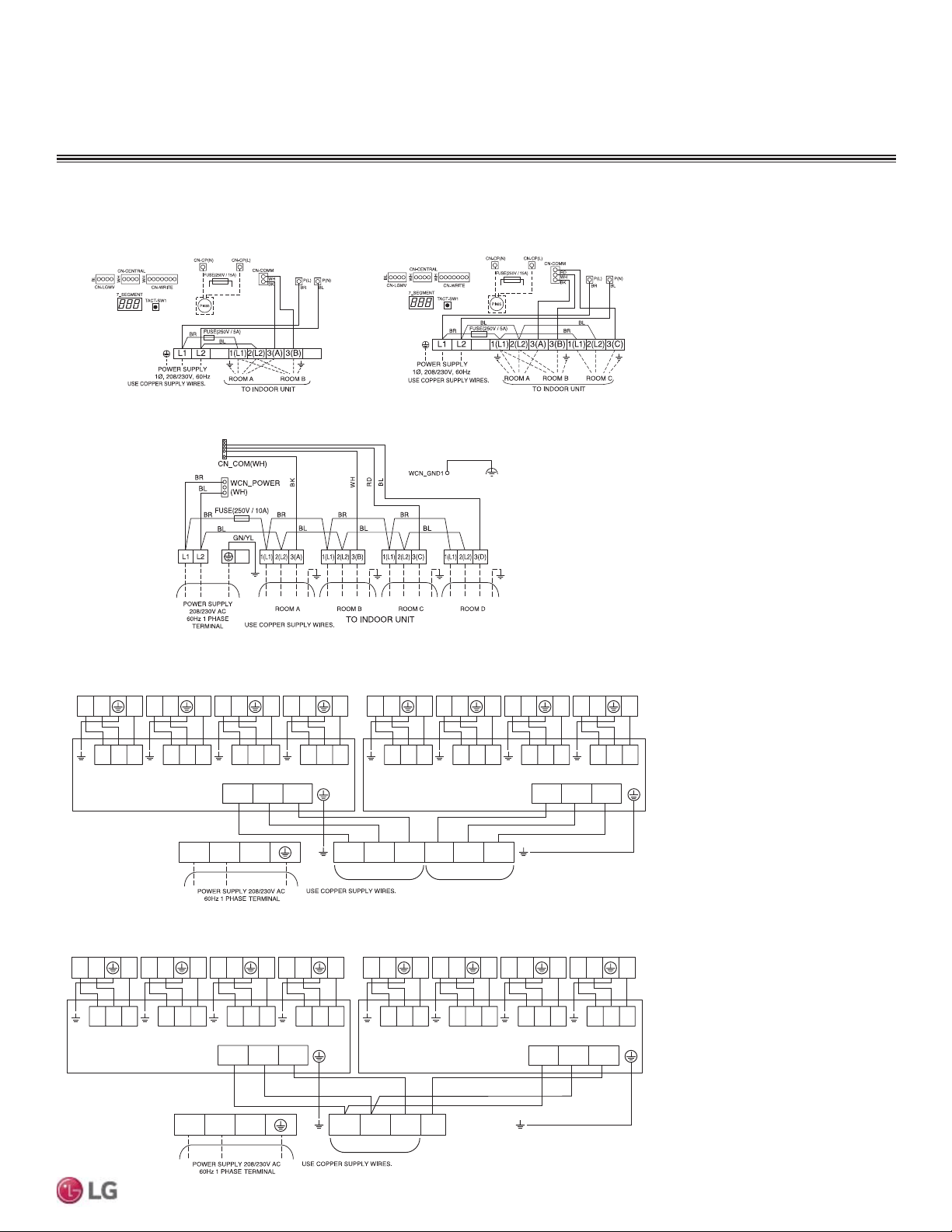
57
Wiring
Due to our policy of continuous product innovation, some specifications may change without notification.
©LG Electronics U.S.A., Inc., Englewood Cliffs, NJ. All rights reserved. “LG” is a registered trademark of LG Corp.
MULTI
F
MAX
MULTI
F
Indoor Unit Terminal Block
A Unit
Indoor Unit Terminal Block
B Unit
Indoor Unit Terminal Block
C Unit
Indoor Unit Terminal Block
D Unit
Indoor Unit Terminal Block
E Unit
Indoor Unit Terminal Block
F Unit
Indoor Unit Terminal Block
G Unit
Indoor Unit Terminal Block
H Unit
Multi F LMU18CHV Multi F LMU24CHV
Multi F LMU30CHV and LMU36CHV
Multi F MAX LMU480HV and LMU540HV
BD Unit (A)
BD Unit (A )
A Room B Room C Room D Room A Room B Room C Room D Room
BD Unit (B )
BD Unit (B)
1(L1) 2(L2) 3(A) 1(L1) 2(L2) 3(B) L1 L2
L(L1) N(L2) S L(L1) N(L2) S
1(L1) 2(L2) 3
L(L1)N(L2) S
1(L1) 2(L2) 3
L(L1)N(L2) S
1(L1) 2(L2) 3
L(L1)N(L2) S
1(L1) 2(L2) 3
L(L1)N(L2) S
1(L1) 2(L2) 3
L(L1)N(L2) S
1(L1) 2(L2) 3
L(L1)N(L2) S
1(L1) 2(L2) 3
L(L1)N(L2) S
1(L1) 2(L2) 3
L(L1)N(L2) S
Figure 78: Detailed View of Outdoor Unit Terminal Blocks / Connections.
WIRING
Power Wiring and Communications Cable Connections
Indoor Unit Terminal Block
A Unit
Indoor Unit Terminal Block
B Unit
Indoor Unit Terminal Block
C Unit
Indoor Unit Terminal Block
D Unit
Indoor Unit Terminal Block
E Unit
Indoor Unit Terminal Block
F Unit
Indoor Unit Terminal Block
G Unit
Indoor Unit Terminal Block
H Unit
Multi F MAX LMU600HV
To BD Units A and B
BD Unit (A )
A Room B Room C Room D Room A Room B Room C Room D Room
BD Unit (B )
1(L1) 2(L2) 3(A) 3(B) L1 L2
L(L1) N(L2) S L(L1) N(L2) S
1(L1) 2(L2) 3
L(L1)N(L2) S
1(L1) 2(L2) 3
L(L1)N(L2) S
1(L1) 2(L2) 3
L(L1)N(L2) S
1(L1) 2(L2) 3
L(L1)N(L2) S
1(L1) 2(L2) 3
L(L1)N(L2) S
1(L1) 2(L2) 3
L(L1)N(L2) S
1(L1) 2(L2) 3
L(L1)N(L2) S
1(L1) 2(L2) 3
L(L1)N(L2) S
Connecting the Power Wiring / Communications Cable to the Outdoor Unit, continued.
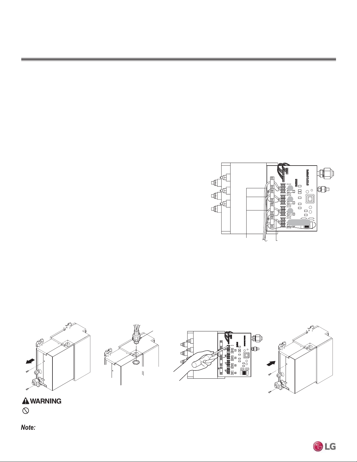
58
MULTI F / MULTI F MAX Outdoor Unit Installation Manual
Due to our policy of continuous product innovation, some specifications may change without notification.
©LG Electronics U.S.A., Inc., Englewood Cliffs, NJ. All rights reserved. “LG” is a registered trademark of LG Corp.
MULTI
F
MAX
MULTI
F
&RQQHFWLQJWKH3RZHU:LULQJ&RPPXQLFDWLRQV&DEOHWR,QGRRU8QLWV
1. Connect power wiring / communications cable (connecting cable) from the outdoor unit to the individual indoor unit terminals following the
wiring diagrams on the outdoor unit and indoor unit control covers.
2. Ensure that the terminal board numbers (A, B, C; 1, 2, 3) and wiring color on the outdoor unit matches the terminal number and wiring
color on the indoor unit. (Terminal board numbers are arranged from top to bottom in order from 1 to 3.)
3. Provide strain relief by securing the wiring / cable to the indoor unit with the factory-supplied clamps.
4. For more installation information for specific indoor units, refer to the separate indoor unit installation manuals on www.lg-dfs.com.
General Instructions
• Always connect power wiring / communications cable matching
the BD unit terminals to their respective indoor units (Example for
three-port BD Unit PMBD3630: A, B, and C).
• Follow the instructions on the nameplates and connect wiring /
cables of the outdoor unit and indoor units to the correct terminals
(1, 2, 3). Always attach each ground wire separately to a ground-
ing screw.
• After completion, secure wiring with wire clamps. Secure wiring
firmly to the indoor unit.
'RQRWXVHWDSSHGZLUHVH[WHQVLRQFRUGVRUVWDUEXUVWW\SHFRQQHFWLRQVDVWKH\PD\FDXVHRYHUKHDWLQJ¿UHHOHFWULFVKRFNphysical injury or
death.
BD Unit Wiring Connection Procedure
1. Remove the BD unit control cover. Unscrew the two (2) screws, and slide the cover off the BD frame following the arrows in the diagram
(Step 1).
2. Draw the power wiring / communications cable through the field-supplied conduit so there is enough length to connect wiring / cable to the
terminals on the BD unit. Secure conduit to the BD unit using a field-supplied lock nut on the interior of the BD unit frame (Step 2).
3. Connect wiring / cable from the outdoor unit to the BD unit terminals, and from the BD unit terminals to the indoor unit terminals following
the wiring diagram on the outdoor unit control cover (Step 3). Allow 11-13/16 inches of slack in the wire harness. Attach wiring / cable to
the BD unit with clamps at four (4) locations.
4. Replace the BD unit control cover following the arrows in the diagram. Tighten the two (2) screws to finish (Step 4).
Lock nut (field supply)
Conduit (field supplied)
Lock nut (field supplied)
Step 1
Step 2
Step 3
Step 4
“A” Room
A
B
C
CN-PWR
Connection Wire to Indoor Units Connection Wire from Outdoor Unit
“B” Room
“C” Room
&RQQHFWLQJWKH3RZHU:LULQJ&RPPXQLFDWLRQV&DEOHWRWKH%UDQFK
Distributor (BD) Unit (Multi F MAX Systems Only)
Always refer to the circuit diagram on the inside of the outdoor unit control cover.
Figure 79: Interior View of a BD Unit (Three-Port PMBD3630 Example
Shown).
Figure 80: BD Unit Wiring Steps.
WIRING
Power Wiring and Communications Cable Connections
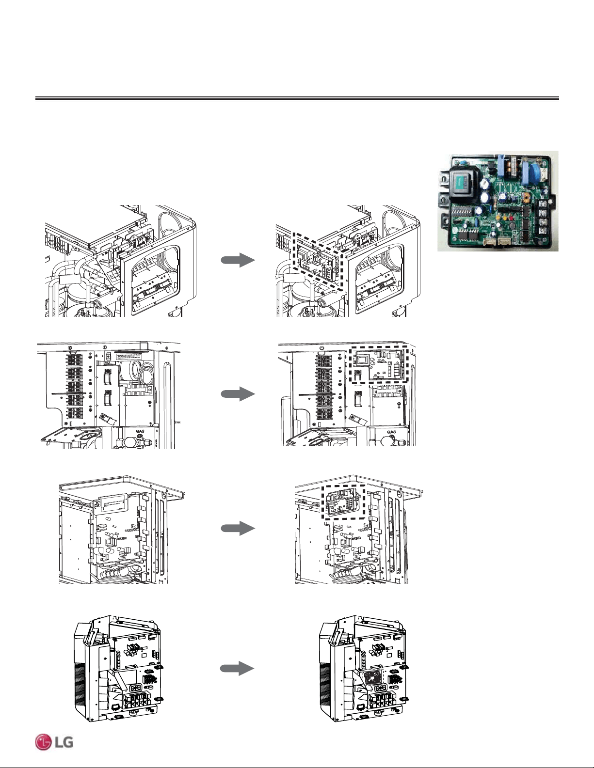
59
Wiring
Due to our policy of continuous product innovation, some specifications may change without notification.
©LG Electronics U.S.A., Inc., Englewood Cliffs, NJ. All rights reserved. “LG” is a registered trademark of LG Corp.
MULTI
F
MAX
MULTI
F
PI485
PI485 V-net Control Integration Board for Outdoor Units adapt Multi F, Multi F MAX systems to a LG VRF
system central protocol for integration with LG central controllers. The PI485 is installed in the Multi F /
Multi F MAX outdoor unit. For more information on PI485 installation, see the PI485 installation manual.
Figure 81: PI485 Board (Appear-
ance may differ depending on
model).
WIRING
Power Wiring and Communications Cable Connections
Multi F LMU18CHV, LMU24CHV
Multi F LMU30CHV, LMU36CHV
T
hi
s
l
a
b
e
l
i
s
s
h
o
u
ld
b
e app
li
ed
in
t
h
e
l
o
c
a
ti
o
n
w
h
e
r
e
L
G
A
P(Sub
PCB
f
o
r
C
e
n
t
r
a
l
C
o
n
t
r
o
l
l
e
r
i
s
ins
t
a
lle
d
.
Pl
e
as
e
co
n
n
e
c
t
t
h
e
w
i
r
e
a
f
t
e
r
in
s
t
a
l
li
n
g
t
h
e
L
G
A
P
.
T
his
i
s
th
e
s
p
a
c
e
f
o
r
in
s
t
a
l
l
a
ti
o
n
o
f
PI
4
8
5
G
a
te
w
a
y.
(
Ac
c
e
s
s
o
ry
)
Pl
e
a
s
e
c
o
n
n
e
c
t
t
h
e
w
i
r
e
a
fte
r
i
ns
ta
l
l
i
ng
PI
4
8
5
G
a
te
w
a
y.
Screw Hole
Screw Hole
M
EZ30
1
71
8
0
2
Multi F MAX LMU480HV, LMU540HV
Multi F MAX LMU600HV
Figure 82: PI485 Installation Area in Multi F and Multi F MAX Outdoor Units.
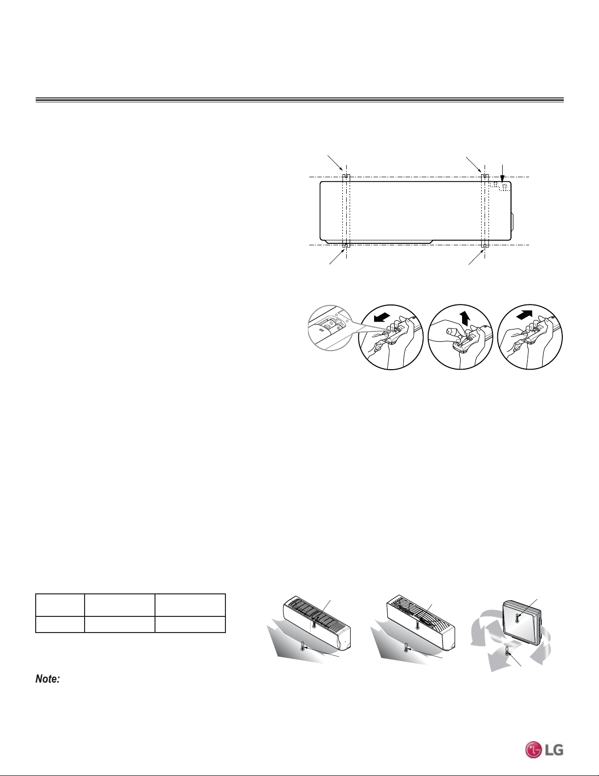
60
MULTI F / MULTI F MAX Outdoor Unit Installation Manual
Due to our policy of continuous product innovation, some specifications may change without notification.
©LG Electronics U.S.A., Inc., Englewood Cliffs, NJ. All rights reserved. “LG” is a registered trademark of LG Corp.
MULTI
F
MAX
MULTI
F
Test Run
After checking the system for leaks and performing the evacuation
procedure, perform a test run. Follow the guidelines below for proper
procedure.
Before the Test Run
1. Check that all condensate tubing, refrigerant piping and power
wiring / communications cables are properly connected.
2. Make sure that the gas and liquid service valves are fully open.
Refrigerant
Type
Outside Ambient
Temperature
Gas Side Service
Valve Pressure
R410A ) 113~142 psig
If the pressure is >142psig, the system is most likely overcharged, and refrigerant should be removed. If the pressure is <113 psig, the system is
most likely undercharged and refrigerant should be added.
Outlet
Temperature
Discharge Air
Inlet Temperature
Outlet
Temperature
Discharge Air
Inlet Temperature
Outlet
Temperature
Discharge Air
Inlet Temperature
Bolt
Refrigerant Pipe
Connection Location
Top of Outdoor Unit
(Looking Down)
Bolt
Bolt
Bolt
Figure 83: Piping Connection on the Outdoor Unit (May Differ Depend-
ing on Outdoor Unit Model).
Figure 84: Installing the Remote Controller Batteries.
Installing the Remote Controller Batteries
As part of the test run, the batteries need to be inserted into the
remote controller, and the remote controller needs to be powered on to
operate the indoor units. To insert the batteries follow the steps below.
For information on using the remote controller, refer to its owner’s
manual.
1. The remote controller needs two AAA (1.5V) batteries for operation.
Remove the battery cover from the back of the remote controller by
pushing downward on the tab at the top of the battery cover and
then lift up to remove.
2. Insert the two new batteries. Align batteries by the (+) and (-)
sides (the interior battery compartment of the remote controller will have clear markings for the (+) and (-) placement).
3. Verify that the batteries have “clicked” into the compartment and are firmly engaged with the contacts on either side of them.
4. Reattach the back cover of the remote controller.
5. Proceed with powering on the remote controller and usage as needed.
Test Run Procedure
1. Start up the system and perform a test run. Operate the system in cooling mode for 15 to 20 minutes.
2. Evaluate performance as the system runs, verifying the outdoor unit and all indoor units and BD units (Multi F MAX systems only) are
working properly. Make notes as needed to address any issues that might be found.
• Check the system refrigerant charge:
• Measure the pressure from the gas side service valve.
• Measure the indoor unit inlet and outlet air temperatures. See table below for the optimum condition of the gas side pressure (system
is in cooling mode).
Figure 85: Inlet and Outlet Temperature Locations on Various Indoor Units.Table 40: Optimum Conditions of the Gas Side Pressure.
TEST RUN
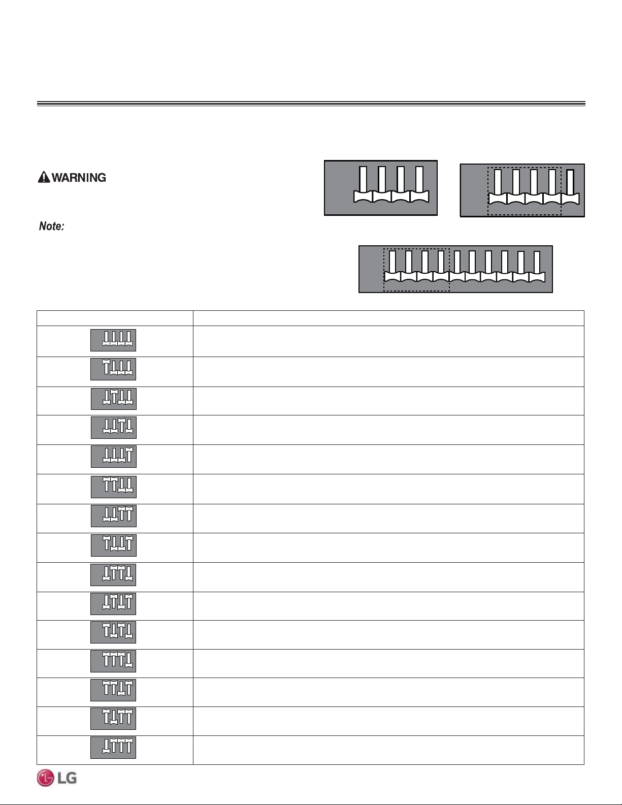
61
Wiring
Due to our policy of continuous product innovation, some specifications may change without notification.
©LG Electronics U.S.A., Inc., Englewood Cliffs, NJ. All rights reserved. “LG” is a registered trademark of LG Corp.
MULTI
F
MAX
MULTI
F
Outdoor Unit DIP Switch Settings
System must be powered off, and then turned back on to apply DIP
switch settings.
Turn off the circuit breaker or shut the power source of the product down
before setting the DIP switch. There is risk of physical injury or death due
to electric shock.
• Unless the applicable DIP switch is set properly, the system may not
work.
• If a specific function is desired, request that the installer set the
appropriate DIP switch during installation.
• 2QO\WKHILUVWIRXU',3VZLWFKHVDUHIXQFWLRQDORQWKH/08
600HV.
12 43
12 43
ON
OFF
DIP SWITCH SETTINGS
Figure 86: LMU18~36CHV
Outdoor Unit DIP Switches (in
Normal Operation Setting).
Table 41: DIP Switch Settings and Functionalities.
DIP Switch Setting Function
Normal Operation (No Function)
Forced Cooling Operation
Wiring Error Check
Reducing Power Consumption (Step 1)
Reducing Power Consumption (Step 2)
Mode Lock (Cooling)
Mode Lock (Heating)
Night Quiet Mode (Step 1)
Night Quiet Mode (Step 2)
Mode Lock (Cooling) + Night Quiet Mode (Step 1)
Mode Lock (Cooling) + Night Quiet Mode (Step 2)
Reducing Power Consumption (Step 1) with Mode Lock (Cooling)
Reducing Power Consumption (Step 2) with Mode Lock (Cooling)
Reducing Power Consumption (Step 1) with Mode Lock (Heating)
Reducing Power Consumption (Step 2) with Mode Lock (Heating)
12 43
12 43
ON
OFF
12 43
12 43
ON
OFF
12 43
12 43
ON
OFF
12 43
12 43
ON
OFF
12 43
12 43
ON
OFF
12 43
12 43
ON
OFF
12 43
12 43
ON
OFF
12 43
12 43
ON
OFF
12 43
12 43
ON
OFF
12 43
12 43
ON
OFF
12 43
12 43
ON
OFF
12 43
12 43
ON
OFF
12 43
12 43
ON
OFF
12 43
12 43
ON
OFF
12 43
12 43
ON
OFF
Figure 87: LMU480-540HV
Outdoor Unit DIP Switches (in
Normal Operation Setting).
Figure 88: LMU600HV Outdoor Unit DIP Switches (in Normal Operation
Setting).
12 43
12 43
ON
OFF
5
5
12 43
12 43
ON
OFF
5
5
67 9810
678910
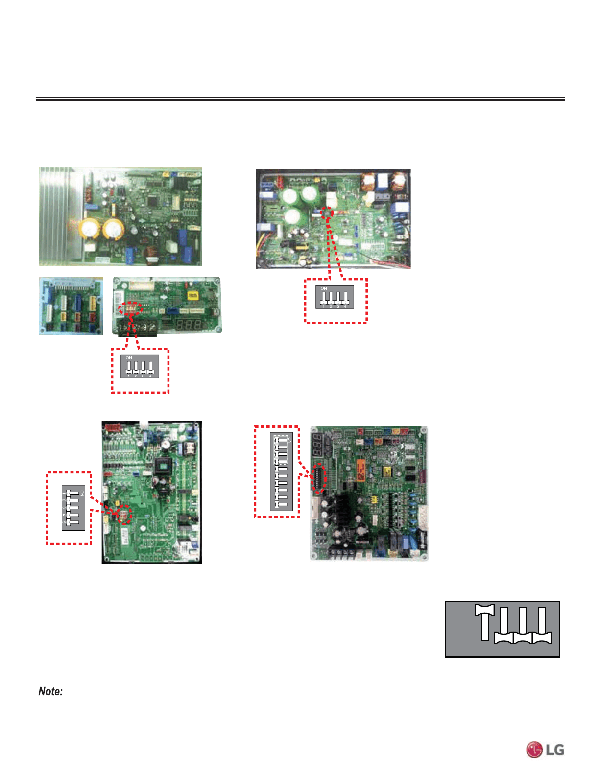
62
MULTI F / MULTI F MAX Outdoor Unit Installation Manual
Due to our policy of continuous product innovation, some specifications may change without notification.
©LG Electronics U.S.A., Inc., Englewood Cliffs, NJ. All rights reserved. “LG” is a registered trademark of LG Corp.
MULTI
F
MAX
MULTI
F
Forced Cooling Operation Function
Use to add refrigerant to the system when outside ambient temperatures are cool (ex.: winter).
1. Shut power down to the system.
2. Set DIP Switch 1 to ON.
3. Turn power on to the system.
4. Verify that the Red LED on the outdoor unit PCB is ON (indicates indoor units are in forced cooling
operation).
5. Add refrigerant.
• ,IWKHJUHHQ/('OLJKWRQWKHRXWGRRUXQLW3&%LV21LWLQGLFDWHVWKHFRPSUHVVRULV2))GXHWRORZSUHVVXUHLQWKHV\VWHP
• Turn DIP Switch 1 to OFF after finishing (Normal Operation setting).
• 2QO\WKHILUVWIRXU',3VZLWFKHVDUHIXQFWLRQDORQWKH/08+9
Multi F LMU18CHV and LMU24CHV
DIP- SW
SW01 N
DIP SW 2
Multi F LMU30CHV and LMU36CHV
Multi F MAX LMU480HV and LMU540HV
DIP-SW01D
12345678910
Multi F MAX LMU600HV
Location of DIP Switches on Multi F and Multi F MAX Outdoor Units
DIP SWITCH SETTINGS
Figure 89: Multi F / Multi F MAX Outdoor Unit DIP Switch Locations.
12 43
12 43
ON
OFF
Figure 90: Forced Cooling DIP
Switch Setting.
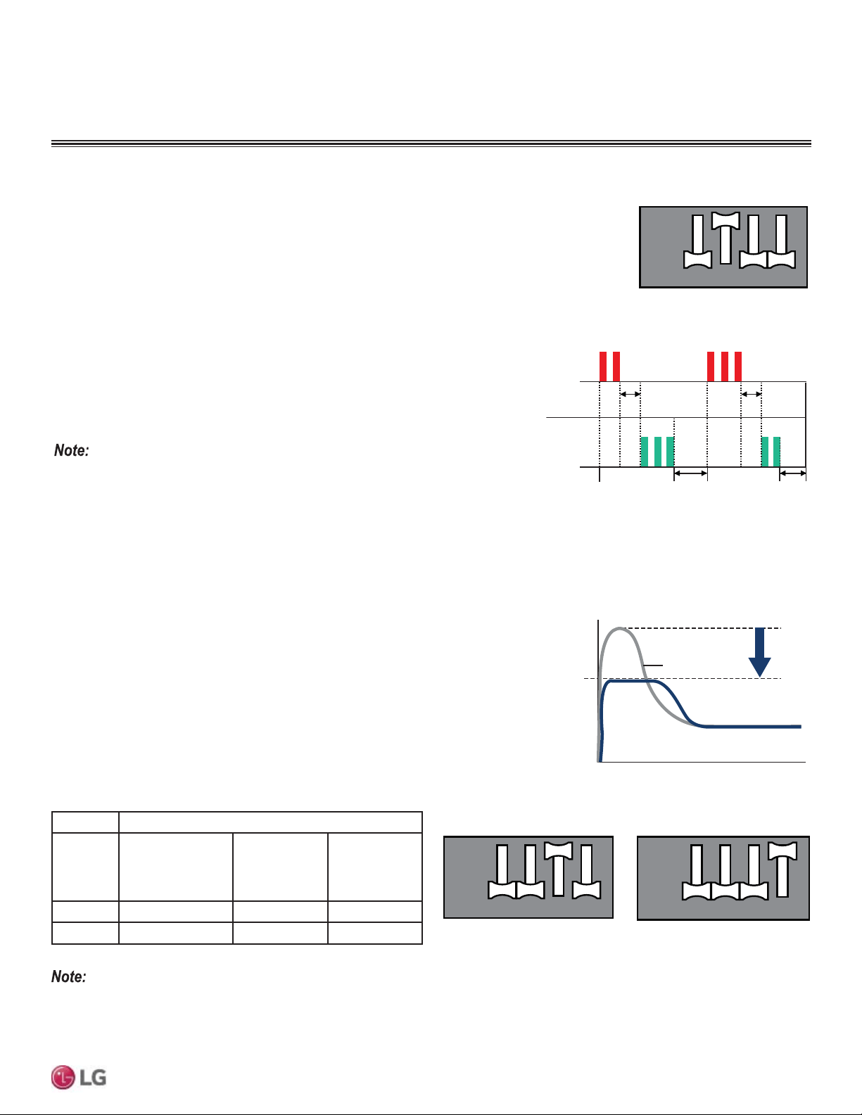
63
Wiring
Due to our policy of continuous product innovation, some specifications may change without notification.
©LG Electronics U.S.A., Inc., Englewood Cliffs, NJ. All rights reserved. “LG” is a registered trademark of LG Corp.
MULTI
F
MAX
MULTI
F
Wiring Error Check
Use to verify if wiring is properly installed.
1. Shut power down to the system.
2. Set DIP Switch 2 to ON.
3. Turn power on to the system.
4. Check if the Red and Green LEDs on the outdoor unit PCB are ON (indicate indoor units are in forced
operation mode).
5. If the wiring is correctly installed, the Green LED will light up. If the wiring is incorrectly installed, the
Red and Green LEDs will blink, indicating which part of the system is in error.
• Red LED = Piping Number
• Green LED = Wiring Number (Room)
Example: If the Red LED blinks twice and the Green LED blinks three times, the second
piping to the third room is in error (see at right).
• If the indoor unit(s) are not communicating properly to the outdoor unit, the Wiring
Error Check cannot operate correctly.
• Only the part of the system in error will be displayed. System will operate correctly
DIWHUWKHHUURULVIL[HG
• ,IRXWGRRUDQGLQGRRUWHPSHUDWXUHVDUHWRRORZH[ZLQWHUWKHZLULQJHUURUFKHFNIXQFWLRQZLOOQRWRSHUDWH5HG/('LV21
• Turn DIP Switch 2 to OFF after finishing (Normal Operation setting).
• 2QO\WKHILUVWIRXU',3VZLWFKHVDUHIXQFWLRQDORQWKH/08+9
12 43
12 43
ON
OFF
Figure 91: Wiring Error Check DIP
Switch Setting.
One (1)
Second
LED 1
(Red)
LED 2
(Green)
Three (3)
Blinks
Two (2)
Blinks
One (1)
Second
One (1)
Second
One (1)
Second
Two (2)
Blinks
Three (3)
Blinks
Figure 92: Wiring Error Check Example.
Reducing Power Consumption
Enables more efficient system operation by reducing the maximum power consumption
value (reducing the MCA).
1. Shut power down to the system.
2. For Step 1, set only DIP Switch 3 to ON. For Step 2, set only DIP Switch 4 to ON.
3. Turn power on to the system.
Table 42: Reducing Power Consumption Current Levels.
Phase 1Ø
Model Multi F
LMU18CHV,
LMU24CHV
Multi F
LMU30CHV,
LMU36CHV
Multi F MAX
LMU480HV,
LMU540HV,
LMU600HV
Step 1 (A) 91322
Step 2 (A) 81121
Power
Consumption
and Current
Normal
Time
Figure 93: Reducing Power Consumption Chart.
12 43
12 43
ON
OFF
12 43
12 43
ON
OFF
Step 1 Step 2
Figure 94: Reducing Power Consumption DIP Switch Settings.
DIP SWITCH SETTINGS
• Reduced Power Consumption reduces outdoor unit capacity.
• 2QO\WKHILUVWIRXU',3VZLWFKHVDUHIXQFWLRQDORQWKH/08+9
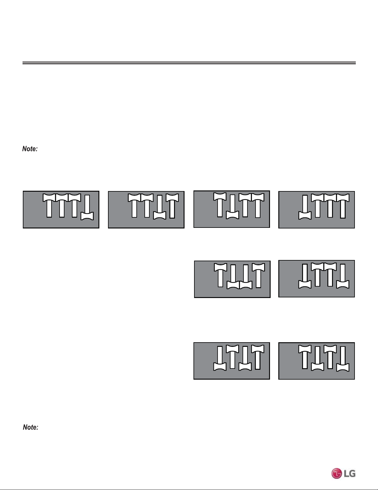
64
MULTI F / MULTI F MAX Outdoor Unit Installation Manual
Due to our policy of continuous product innovation, some specifications may change without notification.
©LG Electronics U.S.A., Inc., Englewood Cliffs, NJ. All rights reserved. “LG” is a registered trademark of LG Corp.
MULTI
F
MAX
MULTI
F
Night Quiet Mode
Lowers the operation sound of the outdoor unit by changing the com-
pressor frequency and fan speeds. Night quiet mode initiates eight
(8) hours after the highest outdoor air temperature is measured, then
is active for nine (9) hours.
1. Shut power down to the system.
2. For Step 1, set only DIP Switches 2 and 3 to ON. For Step 2, set
only DIP Switches 1 and 4 to ON.
3. Turn power on to the system.
• If compressor frequency and fan speed are decreased, cooling capacity also may decrease accordingly.
• Night Quiet Mode can only be used when system is in cooling operation.
• Change the DIP switches if Night Quiet Mode is no longer desired.
• ,ILQGRRUXQLWRSHUDWLRQLVVHWE\WKHIDQVSHHG³3RZHU´1LJKW4XLHW0RGHZLOOQRWIXQFWLRQXQWLOIDQVSHHG³3RZHU´LVFKDQJHG
• 2QO\WKHILUVWIRXU',3VZLWFKHVDUHIXQFWLRQDORQWKH/08+9
Figure 95: Saving Power Consumption with Mode Lock DIP Switch Settings.
12 43
12 43
ON
OFF
Reducing Power Consumption with Mode Lock
Enables more efficient system operation by lowering the maximum power consumption value, as well as locks the mode of operation (Exam-
ple: In a cooling-only server room application where permission to adjust the system mode is highly limited). Changing modes can cause a
change in compressor frequency, which would cause problems with the setting. As such, if this mode is used, it is locked in either cooling or
heating. The function is rarely, if ever, used.
1. Shut power down to the system.
2. Set DIP Switches as indicated below, following the steps and chosen mode.
3. Turn power on to the system.
Step 1: Reducing Saving Power Consump-
tion + Mode Lock (Cooling)
Step 2: Reducing Saving Power Consump-
tion + Mode Lock (Cooling)
12 43
12 43
ON
OFF
Step 1: Reducing Saving Power Consump-
tion + Mode Lock (Heating)
Step 2: Reducing Saving Power Consump-
tion + Mode Lock (Heating)
12 43
12 43
ON
OFF
12 43
12 43
ON
OFF
Figure 96: Night Quiet Mode DIP Switch Settings.
12 43
12 43
ON
OFF
12 43
12 43
ON
OFF
Step 1 Step 2
Night Quiet Mode with Mode Lock
Lowers the operation sound of the outdoor unit by changing the
compressor frequency and fan speeds, as well as locks the mode of
operation. Changing modes can cause a change in compressor fre-
quency, which would cause problems with the setting. As such, if this
mode is used, it is locked in either cooling or heating. The function
is rarely, if ever, used. Night quiet mode initiates eight (8) hours after
the highest outdoor air temperature is measured, then is active for
nine (9) hours.
1. Shut power down to the system.
2. For Step 1, set only DIP Switches 2 and 4 to ON. For Step 2, set
DIP Switches 1 and 3 to ON.
3. Turn power on to the system.
12 43
12 43
ON
OFF
Step 1: Night Quiet Mode + Mode Lock
(Cooling)
Step 2: Reducing Saving Power Consump-
tion + Mode Lock (Cooling)
12 43
12 43
ON
OFF
Figure 97: Night Quiet Mode with Mode Lock DIP Switch Settings.
DIP SWITCH SETTINGS
2QO\WKH¿UVWIRXU',3VZLWFKHVDUHIXQFWLRQDORQWKH/08+9
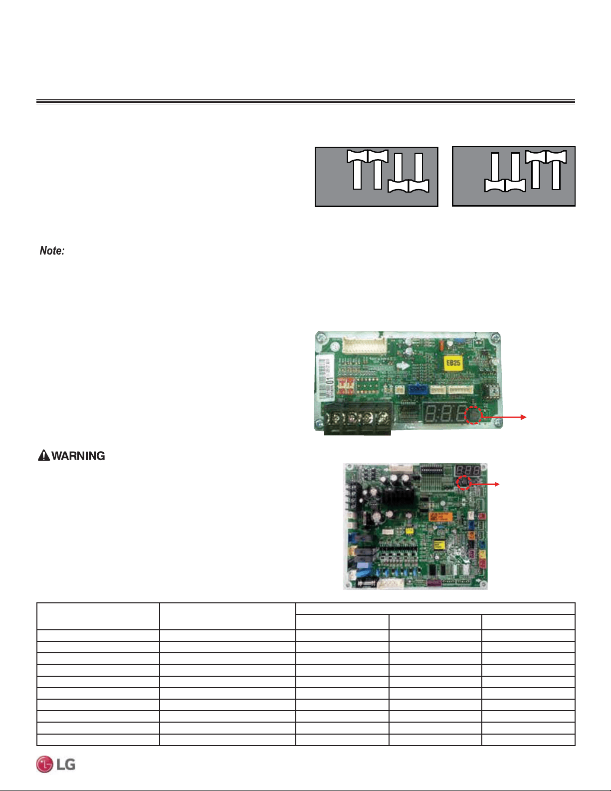
65
Wiring
Due to our policy of continuous product innovation, some specifications may change without notification.
©LG Electronics U.S.A., Inc., Englewood Cliffs, NJ. All rights reserved. “LG” is a registered trademark of LG Corp.
MULTI
F
MAX
MULTI
F
Mode Lock
Prevents mixed mode operation (mode change) in applications
where only one mode is necessary.
1. Shut power down to the system.
2. For Only Cooling Mode Lock, set only DIP Switches 1 and 2 to
ON. For Only Heating Mode Lock, set only DIP Switches 3 and 4
to ON.
3. Turn power on to the system.
12 43
12 43
ON
OFF
Only Cooling Mode Lock Only Heating Mode Lock
12 43
12 43
ON
OFF
Figure 98: Mode Lock DIP Switch Settings.
PCB Display (Multi F LMU18-24CHV
and LMU600HV Models Only)
For Multi F LMU18CHV, LMU24CHV, and LMU600HV outdoor units,
the cycle data can be checked without using LG Monitoring View
(LGMV) Diagnostic Software by pushing TACT-SW1. See below
for the types of cycle information that will be displayed in LGMV.
After first page is displayed, the second page will be subsequently
displayed.
3URWHFW¿QJHUVKDQGVZLWKDQRQFRQGXFWLQJPDWHULDOEHIRUHSXVKLQJ
TACT-SW1. There is risk of physical injury or death due to electric
shock.
TACT-SW1
No. of Pushes
Description
Display
Example First Page Second Page
One (1) Time Low Pressure 890kpa “LP” “89”
Two (2) Times High Pressure 2,900kpa “HP” “290”
Three (3) Times Discharge Temperature & “DS” “85”
Four (4) Times Condenser Outlet Temperature & “CS” “-10”
Five (5) Times Suction Temperature & “SS” “-10”
Six (6) Times Outdoor Unit Air Temperature & “AS” “-10”
Seven (7) Times Current 15A “A” “15”
Eight (8) Times Voltage 230V “V” “230”
Nine (9) Times Compressor Hz 100Hz “F” “100”
Ten (10) Times DC Link Voltage 230V “dc” “230”
Table 43: PCB Display Information.
TACT-SW1
Figure 99: Location of TACT-SW1 (LMU18-24CHV).
DIP SWITCH SETTINGS
2QO\WKH¿UVWIRXU',3VZLWFKHVDUHIXQFWLRQDORQWKH/08+9
Figure 100: Location of TACT-SW1 (LMU600HV).
TACT-SW1
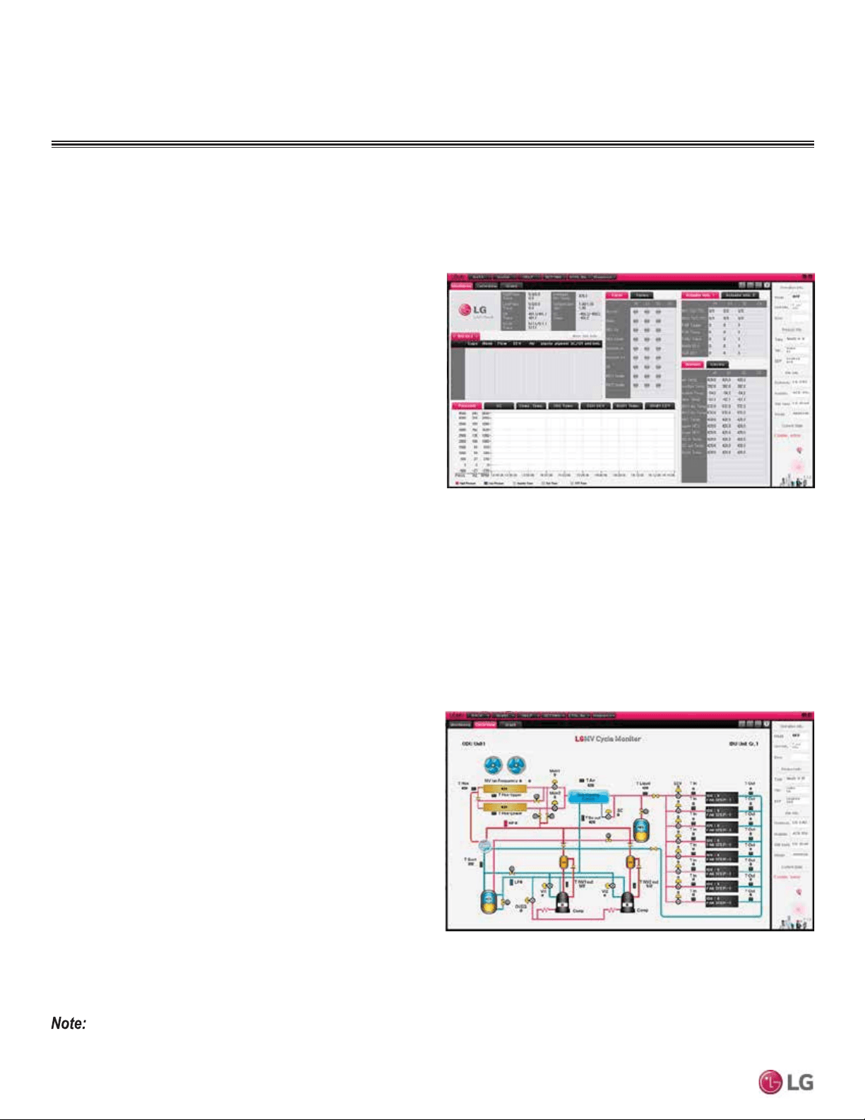
66
MULTI F / MULTI F MAX Outdoor Unit Installation Manual
Due to our policy of continuous product innovation, some specifications may change without notification.
©LG Electronics U.S.A., Inc., Englewood Cliffs, NJ. All rights reserved. “LG” is a registered trademark of LG Corp.
MULTI
F
MAX
MULTI
F
• Actual inverter compressor speed
• Target inverter compressor speed
• Actual outdoor fan speed
• Target outdoor unit fan speed
• Actual superheat
• Target superheat
• Actual subcooler circuit superheat
• Target subcooler circuit superheat
• Main EEV position
• Subcooling EEV position
• Inverter compressor current transducer value
• Outdoor air temperature
• Actual high pressure/saturation temperature
• Actual low pressure/saturation temperature
• Suction temperature
• Inverter compressor discharge temperature
• Front outdoor coil pipe temperature
• Back outdoor coil pipe temperature
• Liquid line pipe temperature
• Subcooler inlet temperature
• Subcooler outlet temperature
• Average indoor unit (IDU) pipe temperature
• Inverter compressor operation indicator light
• Liquid injection
valves’ operation
indicator lights
• Hot gas bypass valve
operation indicator
light
• Four-way reversing
valve operation
indicator light
• Pressure graph
showing actual low
pressure and high
pressure levels
• Error code display
• Operating mode
indicator
• Target high pressure
• Target low pressure
• PCB (printed circuit board) version
• Software version
• Installer name
• Model number of IDUs
• Site name
• Total number of connected IDUs
• Communication indicators
• IDU capacity
• IDU operating mode
• IDU fan speed
• IDU EEV position
• IDU room temperature
• IDU inlet pipe temperature
• IDU outlet pipe temperature
• IDU error code
LG Monitoring View (LGMV) Diagnostic Software
LGMV software (PRCTSL1 and PRCTFE1) allows the service technician or commissioning agent to connect a computer USB port to the
Multi F / Multi F MAX system’s main printed circuit board (PCB) using an accessory cable without the need for a separate interface device.
The monitoring screen for LGMV allows the user to view the following real time data on one screen:
Figure 101: MV Real-time Data Screen
Figure 102: MV Cycleview
,PDJHVRQWKHVHSDJHVDUHH[DPSOHVRI/*09VFUHHQVKRWV$FWXDOLPDJHVPD\GLIIHUGHSHQGLQJRQWKHYHUVLRQRIWKHVRIWZDUHDQGWKHXQLW
installed.
Self Diagnosis Functions
TROUBLESHOOTING
Additional screens can be accessed by tabs on the main screen.
Additional screens include the following:
1. Cycleview: Graphic of internal components including:
• Compressors showing actual speeds
• EEVs
• IDUs
• Temperature and pressure sensors
• Four-way reversing valve
2. Graph: Full screen graph of actual high and low pressures and high
and low pressure limits. A sliding bar enables user to go back in
time and view data.
3. &RQWURO)71(QDEOHVXVHUWRWXUQRQ,'8VLQ)LQFUHPHQWV
4. Useful Tab
• Unit Conversion: Converts metric values to imperial values.
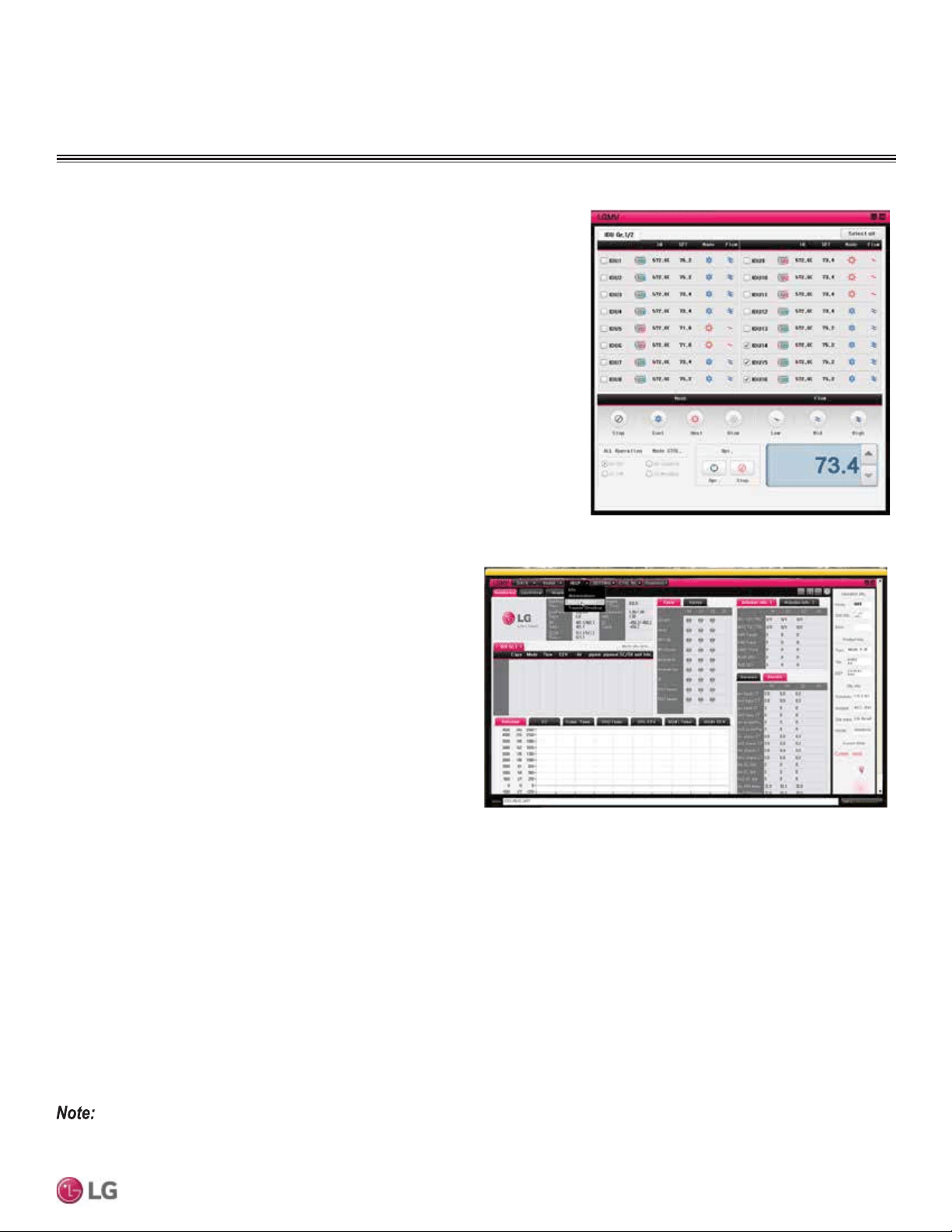
67
Wiring
Due to our policy of continuous product innovation, some specifications may change without notification.
©LG Electronics U.S.A., Inc., Englewood Cliffs, NJ. All rights reserved. “LG” is a registered trademark of LG Corp.
MULTI
F
MAX
MULTI
F
Self Diagnosis Functions
Figure 103: MV Control Indoor Units Screen
The software is available in a high version with all of the features listed above. The low version has all features as the high version without
Target High Pressure and Target Low Pressure values shown on main screen.
In lieu of connecting to the outdoor unit, user has the option to connect to IDU with the use of a USB to RS-485 connector kit. When connect-
ed through IDU, user will not be able to record data.
This software can be used to both commission new systems and troubleshoot existing systems. LGMV data can be recorded to a “.CSV” file
and emailed to an LG representative to assist with diagnostic evaluations.
Recommended Minimum PC Configuration:
Error Codes
LGMV software helps the service technician or commissioning agent
to troubleshoot system operation issues by displaying malfunction
codes. These error codes can be seen on the main screen of the
LGMV software program. For an overview of Multi F / Multi F MAX
system error codes, see Error Codes section. For detailed informa-
tion on how to troubleshoot individual error codes, see the Multi F /
Multi F MAX Service Manual.
Figure 104: Error Code Screen
,PDJHVRQWKHVHSDJHVDUHH[DPSOHVRI/*09VFUHHQVKRWV$FWXDOLPDJHVPD\GLIIHUGHSHQGLQJRQWKHYHUVLRQRIWKHVRIWZDUHDQGWKHXQLWV
installed.
• CPU: Pentium
®
IV 1.6 GHz
• Main Memory: 1G
• Operating System: Windows
®
XP/Vista/7 32 bit (recommended),
64 bit
• Hard Disk: 600 MB when operating
• MS Office 2003, 2007 (recommended) for select reporting
functions
LG Monitoring View (LGMV) Diagnostic Software and Cable - Continued
5. Data
• Data Saving Start: Recording of real time data to a separate file created to be
stored on the user’s computer.
• Data Loading Start: Recorded data from a saved “.CSV” file can be loaded to
create an LGMV session.
6. Monitoring
• Electrical: The lower half of main screen is changed to show Inverter
Compressor Amps, Volts, Power Hz, Inverter control board fan Hz.
TROUBLESHOOTING
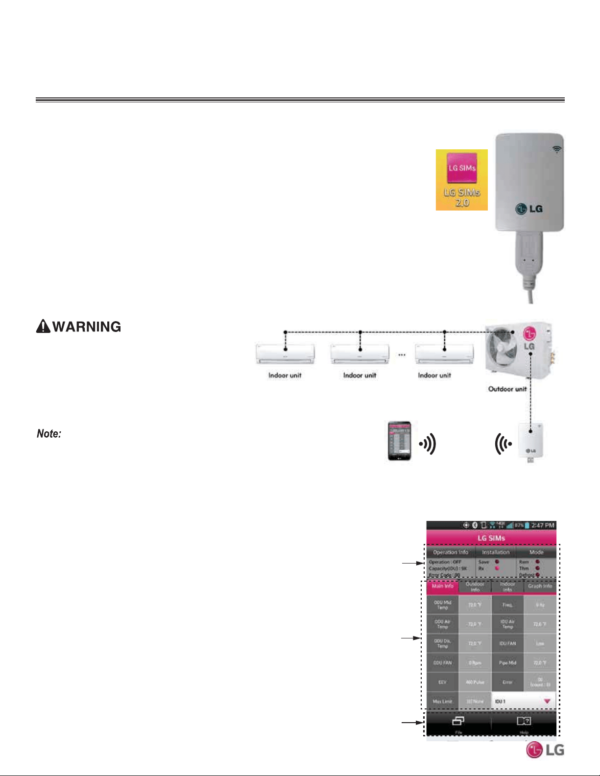
68
MULTI F / MULTI F MAX Outdoor Unit Installation Manual
Due to our policy of continuous product innovation, some specifications may change without notification.
©LG Electronics U.S.A., Inc., Englewood Cliffs, NJ. All rights reserved. “LG” is a registered trademark of LG Corp.
MULTI
F
MAX
MULTI
F
Self Diagnosis Functions
LG SIMs
WLAN Module
LG SIMs App
on Smart Phone
LG SIMS
The SIMs WLAN module and the smart phone app together provide monitoring and trouble-
shooting capability for LG Multi F / Multi F MAX systems. SIMs functions only with LG Duct Free
products.
SIMs can display and graph operational data for the air conditioner system including the indoor
unit and the outdoor unit. SIMs also displays error codes and a troubleshooting guide. A full copy
of the LG SIMs Smart Inverter Monitoring System User’s Manual is available on the www.lghvac.
com website.
To use SIMs you must be a trained HVAC service technician familiar with variable refriger-
ant flow (VRF) systems in general and with LG’s Duct Free System products. You should
understand the inverter air conditioning operation cycle, the meaning of the data displayed by
SIMs, and how to use the data to troubleshoot the system.
Figure 106 shows a Multi F configuration used with the SIMs module and app. LG SIMs can
also be used with Single Zone one-to-one configurations such as the Single Zone Wall Mount
systems.
• The Duct Free System air conditioning system
must run for at least 15–20 minutes before data
collected by SIMs 2.0 is valid for troubleshoot-
ing.
• The free SIMs app must be correctly installed on
your smart phone before using SIMs.
• 6RPH2'8VKDYHDQ/*09H[WHQVLRQFDEOH
accessed by removing the side handle cover.
,IWKH2'8GRHVQRWKDYHWKLVH[WHQVLRQFDEOH
DFFHVVWKH/*09FRQQHFWRUE\UHPRYLQJWKHWRS
cover of the ODU.
High voltages capable of causing death are used
in this equipment. Outdoor unit power remains con-
QHFWHGGXULQJWKLVSURFHGXUH7DNHH[WUHPHFDXWLRQ
not to touch electrical components or connections.
Failure to observe this warning can result in death
or severe injury.
Figure 105: LG SIMs App and WLAN Module
Figure 106: SIMs WLAN Module to Typical DFS System
Figure 107: SIMs App Main Info Screen
The main screen is the first screen displayed after wireless connection is
established. Tap the Main Info tab to display current readings regarding
your indoor and outdoor unit(s). The Operational Info area of the screen
will show active functions or modes by illuminating the light to the right of
the function.
Additional Help information can be accessed by tapping the Help Menu
buttons at the bottom of this screen.
Operational
Information
AC Cycle
Information on
Main Info Tab
Help Menu
(File is Factory Use Only)
SIMs App Main Info Screen
TROUBLESHOOTING
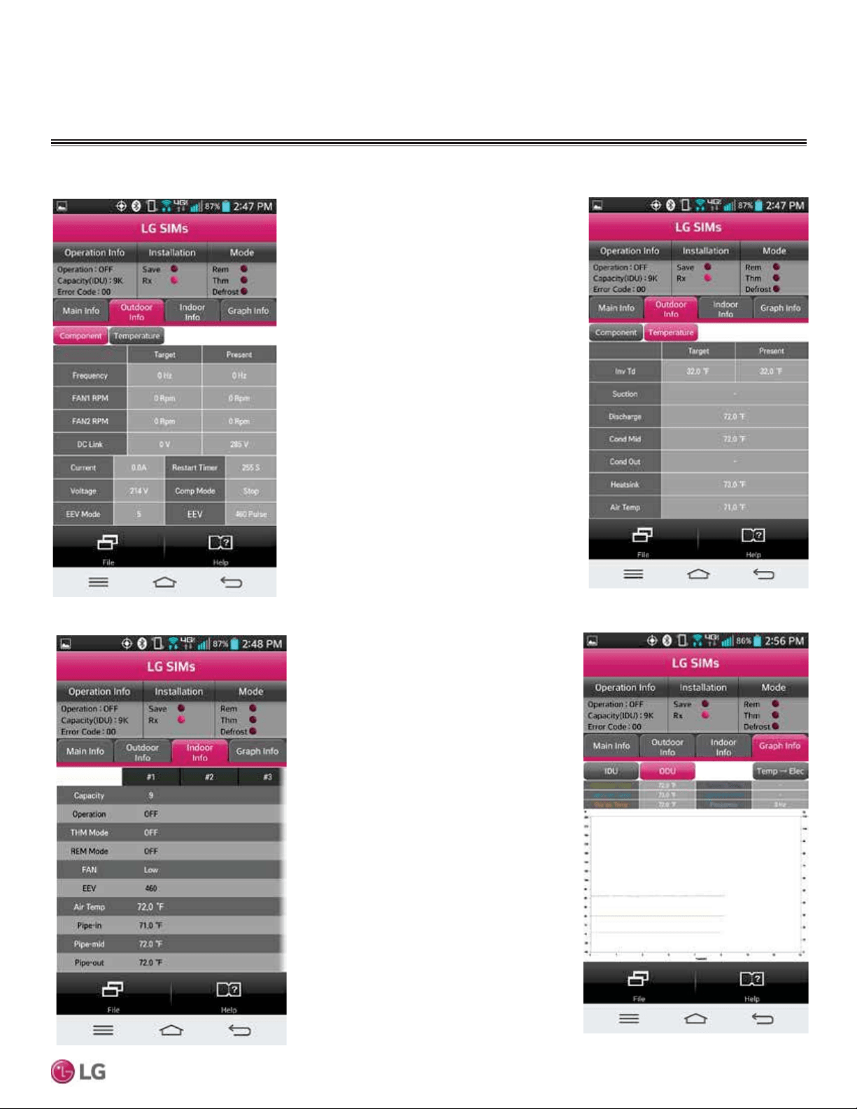
69
Wiring
Due to our policy of continuous product innovation, some specifications may change without notification.
©LG Electronics U.S.A., Inc., Englewood Cliffs, NJ. All rights reserved. “LG” is a registered trademark of LG Corp.
MULTI
F
MAX
MULTI
F
Self Diagnosis Functions
SIMs App Screens
Outdoor Info/
Component Screen
Displays the following
information:
• Frequency
• FAN1 RPM
• FAN2 RPM
• DC Link
• Current
• Voltage
• EEV Mode
• Restart Timer
• Comp Mode
• EEV
Indoor Info Tab
Displays the following
information:
• Frequency
• Operation
• THM Mode
• REM Mode
• FAN
• EEV
• Air Temp
• Pipe-in
• Pipe-mid
• Pipe-out
Graph Info Tab
This tab, has three sub
sections:
• IDU - Indoor Unit
Temperature graph.
Displays IDU informa-
tion in graph format. In-
formation displayed is
for the IDU # selected
on the Main screen.
• ODU - Outdoor Unit
Temperature and Fre-
quency graph. Displays
ODU information in
graph format.
• ODU Electric - Out-
door Unit Electric data
graph is displayed.
Outdoor Info/
Temperature Screen
Displays the following
information:
• Inv TD
• Suction
• Discharge
• Cond Mid
• Cond Out
• Heatsink
• Air Temp
TROUBLESHOOTING
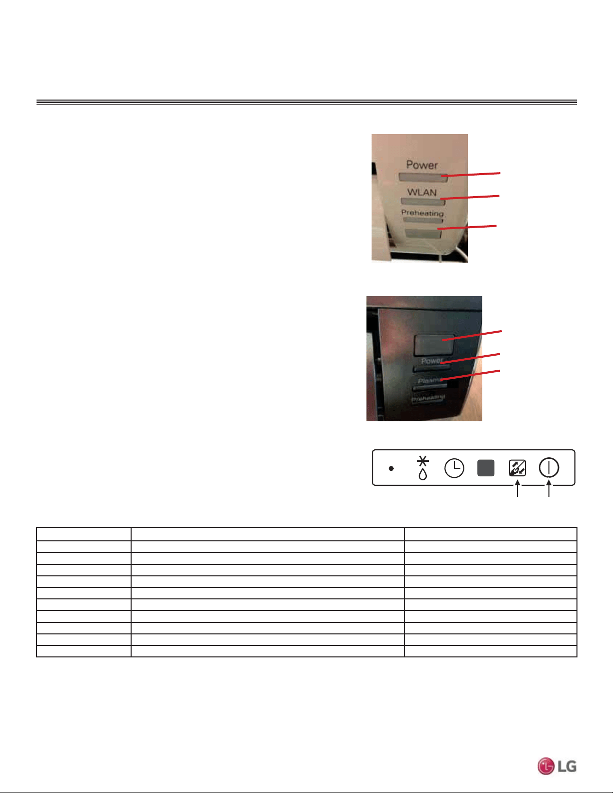
70
MULTI F / MULTI F MAX Outdoor Unit Installation Manual
Due to our policy of continuous product innovation, some specifications may change without notification.
©LG Electronics U.S.A., Inc., Englewood Cliffs, NJ. All rights reserved. “LG” is a registered trademark of LG Corp.
MULTI
F
MAX
MULTI
F
Error Code Description Indoor Unit Operation Status
00 No error ON
01 Indoor unit room temperature sensor error OFF
02 Indoor unit inlet pipe sensor error OFF
03 Controller error OFF
04 Drain pump error (optional) OFF
05 Communication error between indoor unit and outdoor units OFF
06 Indoor unit outlet pipe sensor error OFF
07 Different mode operation error OFF
09 Indoor unit EPROM error OFF
10 Indoor unit BLDC motor fan lock OFF
Receiver
LED 1
(UNITS PLACE)
LED 2
(TENS PLACE)
Figure 108: Standard Wall-Mounted Indoor Unit LEDs.
Figure 109: Art Cool Mirror Wall-Mounted Indoor Unit
LEDs.
Number of Blinks = Error Code
LED 1: Units PlaceLED 2: Tens Place
Error Codes
Troubleshooting Using Error Codes
Refer to Tables 44 and 45 for error codes that are generated from
the indoor and outdoor units. These codes indicate different types of
unit failures, assist in self-diagnosis, are the most common that will
manifest through these units. Error codes are displayed on indoor unit
LEDs, wired remote controllers, the outdoor unit PCB, and through LG
Monitoring View (LGMV) diagnostic software.
Systems may generate additional codes not listed here. Contact LG
Support if these types of errors are seen and a simple power down and
boot up has not corrected the issue. Do not attempt to fix the system
yourself.
• If two or more errors occur simultaneously, the highest error code
QXPEHULVGLVSOD\HG¿UVW
• After error is resolved, the error code does not display.
Decoding the Error Display
See images and table below for indoor unit error codes, location of
LEDs, and operation status.
The first and second number on the LED indicates error number. Ex-
ample: 21 = LED1 (Red light) 2x blink, LED2 (Green light) 1x blink.
Error Code Nomenclature Definitions
• MICOM: Non-volatile memory chip where unit setup information is
stored.
• EPROM: Non-volatile memory chip where device identification, size,
and factory defined default component operating parameters are
stored.
Figure 110: Ceiling Cassette Indoor Unit LEDs.
Table 44: Indoor Unit Error Codes.
TROUBLESHOOTING
LED 1
(UNITS PLACE)
LED 2
(TENS PLACE)
Receiver
71
Wiring
Due to our policy of continuous product innovation, some specifications may change without notification.
©LG Electronics U.S.A., Inc., Englewood Cliffs, NJ. All rights reserved. “LG” is a registered trademark of LG Corp.
MULTI
F
MAX
MULTI
F
Error
Code
Description
No. of Times Outdoor Unit LEDs
Blink
Outdoor
Operation
Status
LED01 (Red) LED02 (Green)
21 DC Peak (IPM Fault); Compressor DC voltage was too high 2X 1X OFF
22 Current Transformer2 (CT2) error; Alternating current (AC) input too high 2X 2X OFF
23
DC Link Low Voltage (DC Link Voltage is <140VDC)
2X 3X OFF
DC Link High Voltage (DC Link Voltage is >420VDC)
25 AC Low / High Voltage 2X 5X OFF
26 DC Compressor Position Error (Compressor failed to start properly) 2X 6X OFF
27 PSC / PFC Fault; Input current to inverter compressor PCB is too high 2X 7X OFF
29 Current to inverter compressor is too high 2X 9X OFF
32 Inverter compressor discharge pipe (D-Pipe) temperature is too high 3X 2X OFF
35 Low Pressure Error; Pressure dropped below recommended limits 3X 5X OFF
39 Communication Error between PFC MICOM and Inverter MICOM 3X 9X OFF
40 CT Sensor Error; Thermistor is disconnected or has shorted out 4X - OFF
41 Inverter compressor discharge pipe (D-Pipe) sensor is disconnected or has shorted out 4X 1X OFF
43 High pressure sensor is disconnected or has shorted out 4X 3X OFF
44 Outdoor air sensor is disconnected or has shorted out 4X 4X OFF
45 Mid-pipe thermistor of outdoor unit condenser is disconnected or has shorted out 4X 5X OFF
46 Outdoor unit suction piping thermistor is disconnected or has shorted out 4X 6X OFF
48 Outlet piping (liquid) of condenser is disconnected or has shorted out 4X 8X OFF
51
Combination ratio (capacity) is out of range; Total nominal indoor unit capacity is<50%
or >130% of the outdoor unit capacity
5X 1X OFF
53 Communication failure between outdoor unit and indoor unit(s) 5X 3X OFF
54 Outdoor unit is not wired properly (ex: reversed phase) 5X 4X OFF
60 Outdoor unit printed circuit board (PCB) EPROM check sum error 6X - OFF
61 Condenser coil thermistor temperature is too high 6X 1X OFF
62 Outdoor unit inverter compressor PCB heat sink temperature is too high 6X 2X OFF
65 Heat sink thermistor is disconnected or has shorted out 6X 5X OFF
67 Outdoor unit brushless direct current (BLDC) fan motor lock error 6X 7X OFF
73 Outdoor unit PFC overcurrent (peak) error 7X 3X OFF
Error Codes
Table 45: Outdoor Unit Error Codes.
TROUBLESHOOTING
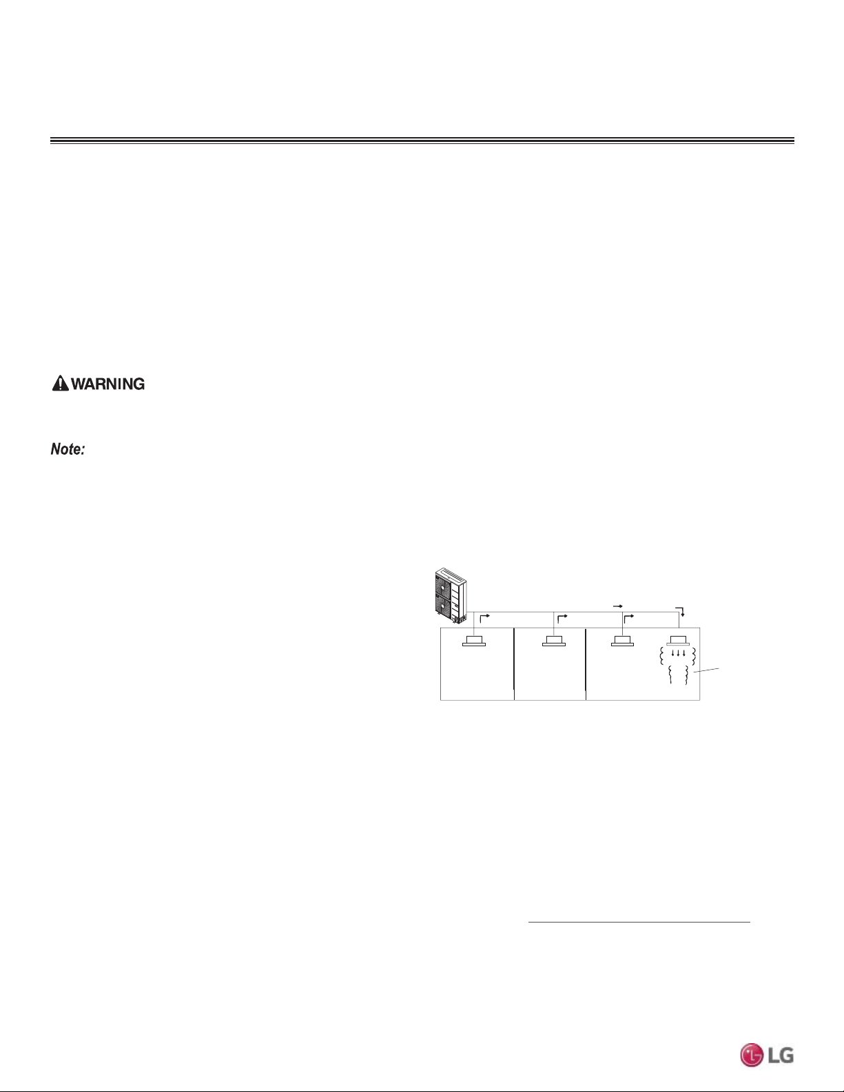
72
MULTI F / MULTI F MAX Outdoor Unit Installation Manual
Due to our policy of continuous product innovation, some specifications may change without notification.
©LG Electronics U.S.A., Inc., Englewood Cliffs, NJ. All rights reserved. “LG” is a registered trademark of LG Corp.
MULTI
F
MAX
MULTI
F
Amount of
Factory-Charged
Refrigerant per
Outdoor Unit
Amount of
Additional
Refrigerant
Trim Charge
Refrigerant Concentration Limit (RCL) Calculations
To calculate total refrigerant amount per system:
&DXWLRQVIRU5HIULJHUDQW/HDNV,QWURGXFWLRQ
ASHRAE Standards 15 and 34 offer guidelines that address refrigerant safety and the maximum allowable concentration of refrigerant in an
occupied space. Refrigerant will dissipate into the atmosphere, but a certain volume of air is required for this to occur safely. For R410A re-
frigerant, the maximum allowable concentration is 0.026 lbs./ft
3
per 1,000 ft
3
of air in an occupied space. Buildings with twenty-four (24) hour
occupancy allow half of that concentration.
1
ASHRAE Standards 15 and 34 assume that if a system develops a leak, its entire refrigerant charge will dump into the area where the leak
occurs. To meet ASHRAE Standards 15 and 34, calculate the refrigerant concentration that may occur in the smallest room volume on
the system, and compare the results to the maximum allowable concentration number (see below for information on how to calculate the
refrigerant concentration).
1
Also consult state and local codes in regards to refrigerant safety.
1
$PHULFDQ6RFLHW\RI+HDWLQJ5HIULJHUDWLRQDQG$LU&RQGLWLRQLQJ(QJLQHHUV,QF$6+5$($WODQWD*$$6+5$(,QF,QIRUPDWLRQDERXW
ASHRAE Standard 15 / 34 and addenda current as of the date of this publication.
Take appropriate actions at the end of HVAC equipment life to recover, recycle, reclaim or destroy R410A refrigerant according to applicable US
EPA rules.
Total System
Refrigerant
Charge
=
To calculate the potential refrigerant concentration level (RCL):
1. Measure the occupied space dimensions (in feet).
2. Calculate the cubic foot volume of air in the smallest occupied
space. (To obtain a detailed overview of the RCL, perform the
same calculations to the second smallest zone, the third smallest
zone until the RCL is obtained for all zones. Also, pay special
attention to areas such as basements, etc., where refrigerant
cannot dissipate easily.)
3. Divide the refrigerant charge of the Multi Zone system serving the
area in pounds by the results of step 1.
4. If the calculation indicates that the potential refrigerant concen-
tration level is higher than the allowed RCL, increase the cubic
volume of the smallest occupied space or modify the piping
system design.
5. The allowable RCL limit for most applications must be equal to
or less than 0.026 lbs./ft
3
. However, in special occupied spaces,
such as hospitals and nursing homes, where occupants may have
limited mobility, the allowable RCL limit is cut in half. See ASHRAE
Standard 34 and local codes for detailed information.
1
RCL (lbs./ft
3
) =
Total System Refrigerant Charge (lbs.)
Volume of Smallest Occupied Space (ft
3
)
9HULI\WKHPD[LPXPUHIULJHUDQWFRQFHQWUDWLRQOHYHOLQWKHVSDFHZKHUHWKHLQGRRUXQLWZLOOEHPRXQWHGPHHWVWKHFRQFHQWUDWLRQOLPLWIRUWKH
DSSOLFDWLRQ,IWKHUHIULJHUDQWOHDNVDQGVDIHW\OLPLWVDUHH[FHHGHGLWFRXOGUHVXOWLQSHUVRQDOLQMXULHVRUGHDWKIURPR[\JHQGHSOHWLRQ
Outdoor Unit
Direction of Refrigerant Flow
Indoor Unit
Zone into which the
entire charge of
refrigerant leaks.
Indoor Unit Indoor Unit
Indoor Unit
Figure 111: Example of R410A Refrigerant Leak Location.
CAUTIONS FOR REFRIGERANT LEAKS
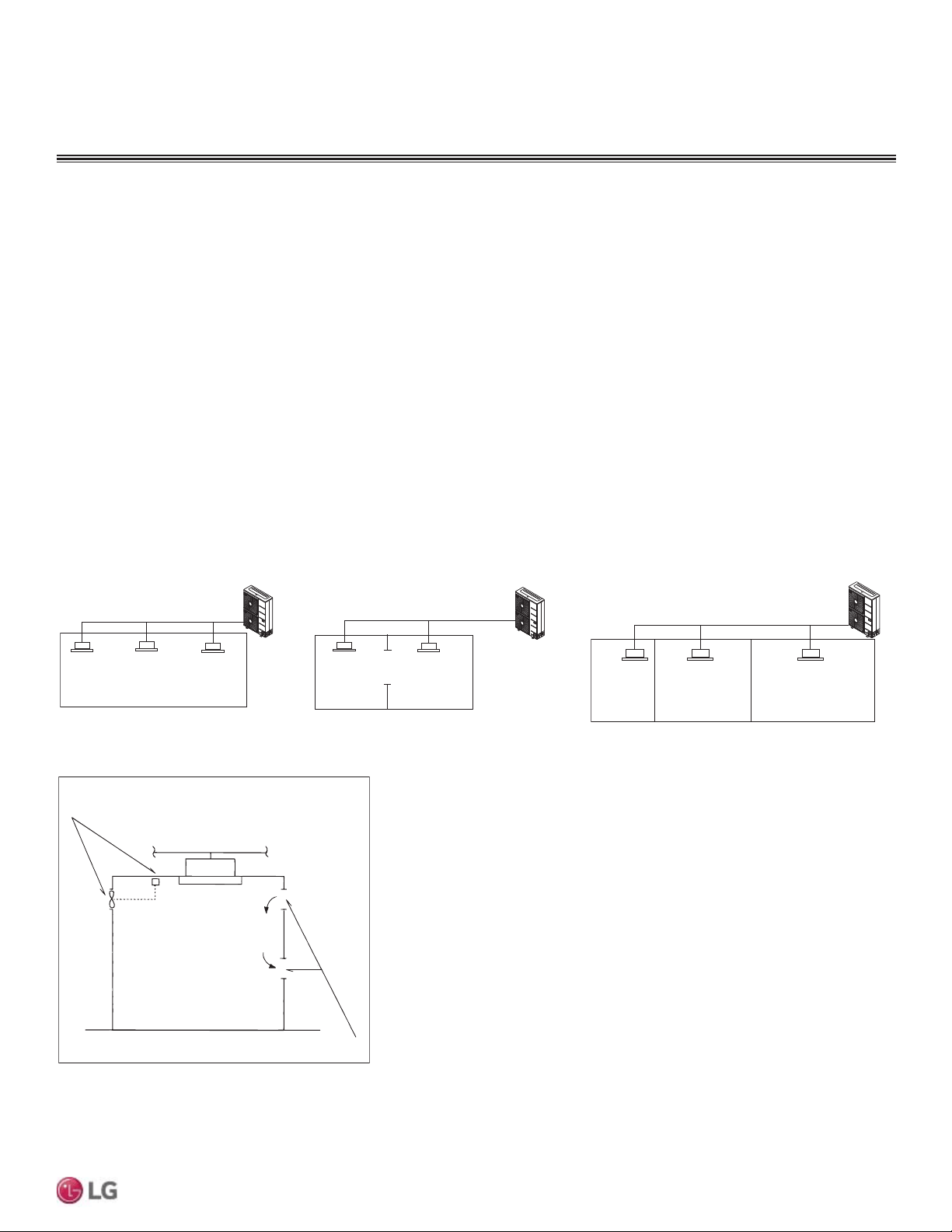
73
Wiring
Due to our policy of continuous product innovation, some specifications may change without notification.
©LG Electronics U.S.A., Inc., Englewood Cliffs, NJ. All rights reserved. “LG” is a registered trademark of LG Corp.
MULTI
F
MAX
MULTI
F
To determine the volume of an occupied space, the designer must also determine which ones are connected, not connected, or ventilated
(refer to Standard 34).
If the calculated RCL is above the allowable limit, there are two primary methods used to lower the RCL:
1. Increase the volume of the occupied space.
2. Decrease the size of the refrigerant charge.
Per Standard 34-2007, acceptable methods used to increase the volume of an occupied space include:
• Install transfer ducts between rooms.
• 8QGHUFXWDQGRYHUFXWGRRUVSDUWLWLRQVRIFXELFYROXPHRIVSDFHZLWKLQD]RQH
• $GGDQRSHQLQJZLWKRXWDGRRUSDUWLWLRQVRIFXELFYROXPHRIVSDFHZLWKLQD]RQH
• ,QFOXGHYHQWLODWLRQJULOOHVLQGRRUVLQFOXGHYHQWLODWLRQLQOHWVRXWOHWVSDUWLWLRQVRIFXELFYROXPHRIVSDFHZLWKLQD]RQH
• ,QFOXGHWKHDUHDDERYHWKHFHLOLQJDVSDUWRIWKHUHWXUQRUVXSSO\DLUSDWKSDUWLWLRQVRIFXELFYROXPHRIVSDFHZLWKLQD]RQH
• Install a mechanical ventilator linked to a gas leak detector.
• Change the indoor unit type (wall mounted to ceiling cassette) / position.
Figure 112: Examples of Zones.
Figure 113: Examples of Acceptable Ventilation Methods.
Mechanical Ventilator Linked
to a Gas Leak Detector
Ventilation Inlet / Outlet
Indoor Unit
Indoor Unit
Smallest Zone
in System
Indoor Unit Indoor Unit
Outdoor Unit
Outdoor Unit
Indoor Unit
Opening
Partition
Zone includes partition
(but no door), or includes
openings ≥0.15% of floor
volume (openings can be
located both above and
below the door)
Outdoor Unit
Indoor UnitIndoor Unit Indoor Unit Indoor Unit
Without Partition. With Partition / With Opening to
Adjoining Room.
With Partition / Without Opening to
Adjoining Rooms.
CAUTIONS FOR REFRIGERANT LEAKS
MULTI
F
MAX
MULTI
F
Due to our policy of continuous product innovation, some specifications may change without notification.
©LG Electronics U.S.A., Inc., Englewood Cliffs, NJ. All rights reserved. “LG” is a registered trademark of LG Corp.
INSTALLATION CHECKLIST
PAGE 1
Major Component Rough-In
Description Check
All Multi F / Multi F MAX outdoor units were connected properly per local code and the product installation procedures.
All literature and bagged accessories have been removed from the fan discharge.
Indoor units and branch distribution unit(s) (Multi F MAX only) are installed, properly supported, and located indoors in a non-cor-
rosive environment.
Multi F / Multi F MAX gravity condensate drain line was connected and routed where it properly drains away or, if installed in a
mechanical room, was connected and properly routed to a drain terminal.
Piping and Insulation
Description Check
Copper
Over 5/8 inches—Rigid ACR only.
5/8 inches and under—Can use soft ACR.
15% silver brazing material only.
All refrigerant pipes and valves were insulated separately. Insulation butts up against the walls of the indoor units. No gaps or
cracks. Insulation was not compressed at clamps and hangers.
LG Y-branches were used per manufacturer’s recommendations.
(Optional) Full port ball valves for all indoor units. (Schrader between the valve body and the indoor units.)
Condensate piping installed on indoor units–material used is acceptable under local code. Insulated as necessary to prevent
condensation.
Brazing Practices
Description Check
Medical grade (there are 4 available) dry nitrogen for purging during brazing was used (constant 3 psi while brazing).
Installation
(For more information on any procedure, refer to the detail provided in the Indoor Unit Installation Manuals.)
Refrigerant Piping
Description Check
Have in possession a copy of the “As-Designed” LATS Multi F piping tree diagram. BEFORE ANY FIELD PIPE SIZE OR LENGTH
CHANGES ARE MADE, PROPOSED CHANGES MUST BE FORWARDED TO THE DESIGN ENGINEER SO THAT THEY CAN
INPUT THE CHANGES INTO LATS and RE-ISSUE A NEW LATS PIPING TREE DIAGRAM. Installer must receive change authori-
zation from the design engineer, because any change made requires the review of the entire tree diagram and verification that the
change did not impact the size of piping segments in other parts of the system.
All pipe materials were properly stored, capped, and clean. All burrs were removed after cutting and pipe ends were reamed
before brazing.
During refrigerant pipe installation, for each segment of pipe, a record was made of the pipe length (including expansion loops,
offsets, double-back sections), and sizes, as well as the quantity and type of elbows used.
All long runs of straight pipe were provided with expansion loops.
(QVXUH<EUDQFKHVDUHLQVWDOOHGZLWKQRPRUHWKDQRIKRUL]RQWDO
(QVXUH<EUDQFKHVDUHLQVWDOOHGZLWKQRPRUHWKDQRIYHUWLFDO
A torque wrench and backup wrench were used to tighten all flare connections.
The back side of all flares were lubricated with a small drop of PVE refrigeration oil before tightening flare fittings.
(QVXUHDOOILHOGPDGHIODUHVDUH8VHIDFWRU\VXSSOLHGIODUHQXWVRQO\
Pipe segments were properly supported and all wall penetrations were sleeved.
Pipe insulation was not compressed at any point.
Y-branches were properly supported per details provided in the installation manual.
Ensure Y-branches are installed in the correct direction. Flow is always from the single end to the double end.
No oil traps, solenoid valves, sight glasses, filter driers, or any other unauthorized refrigerant specialties were present.
(Optional) R410A rated full port ball valves were used at all indoor units and wherever appropriate in the refrigerant piping network.
%HVWSUDFWLFHLQFOXGLQJDPLQLPXPRIƎRIVWUDLJKWSLSHZDVLQVWDOOHGEHWZHHQHDFKHOERZ
MULTI
F
MAX
MULTI
F
Due to our policy of continuous product innovation, some specifications may change without notification.
©LG Electronics U.S.A., Inc., Englewood Cliffs, NJ. All rights reserved. “LG” is a registered trademark of LG Corp.
&RQGHQVDWH3XPS'UDLQ,QVWDOODWLRQ
Description Check
Indoor unit condensate drain pipes were installed correctly.
$OOFRQGHQVDWHYHUWLFDOULVHUVDUHHTXDOWRRUOHVVWKDQƎIURPWKHERWWRPRIWKHLQGRRUXQLW
Indoor units with condensate pumps were level. Units with gravity drains were level or slightly canted toward the drain connection
and are supported properly.
Pumped condensate drain lines were properly connected (do not have traps, and connect to the top surface of the main drain
line).
Power Wire and Communications Cables
Description Check
Power wiring was connected to a single phase 208-230V source.
Ground wire was installed and properly terminated at the unit.
The power supplied was clean with voltage fluctuations within specifications. (±10% of nameplate).
Power wiring to the Multi F / Multi F MAX outdoor unit was installed per all local electrical code requirements.
Power wiring to the indoor units and branch distribution unit(s) (Multi F MAX only) was installed per all local electrical code
requirements.
LG-supplied cable was used between each indoor unit and its zone controller. No cables were spliced and no wire caps are
present.
Communication type RS-485–BUS type.
Communications/power were a minimum of 18-AWG, four (4) conductor, stranded, shielded or unshielded, with insulation material
per local code. If shielded, must be ground to outdoor unit only. Cable segment shields were tied together.
Used appropriate crimping tool to attach ring or spade terminals at all power wiring and control cable terminations.
Power and control wires were run in the same conduit (ODU to IDU only) as provided in the product installation manual.
Power to ODU and power/communications to IDU cannot be run in the same conduit and must be separated per manufacturer’s
guidelines.
INSTALLATION CHECKLIST
PAGE 2
MULTI
F
MAX
MULTI
F
Due to our policy of continuous product innovation, some specifications may change without notification.
©LG Electronics U.S.A., Inc., Englewood Cliffs, NJ. All rights reserved. “LG” is a registered trademark of LG Corp.
INSTALLATION CHECKLIST
PAGE 3
Major Component Rough-In
Piping and Insulation
Brazing Practices
MULTI
F
MAX
MULTI
F
Due to our policy of continuous product innovation, some specifications may change without notification.
©LG Electronics U.S.A., Inc., Englewood Cliffs, NJ. All rights reserved. “LG” is a registered trademark of LG Corp.
Installation—Refrigerant Piping
Installation—Branch Distribution Unit (Multi F MAX Systems Only)
,QVWDOODWLRQ²&RQGHQVDWH3XPS'UDLQ,QVWDOODWLRQ
Installation—Power Wire and Communications Cables
INSTALLATION CHECKLIST
PAGE 4
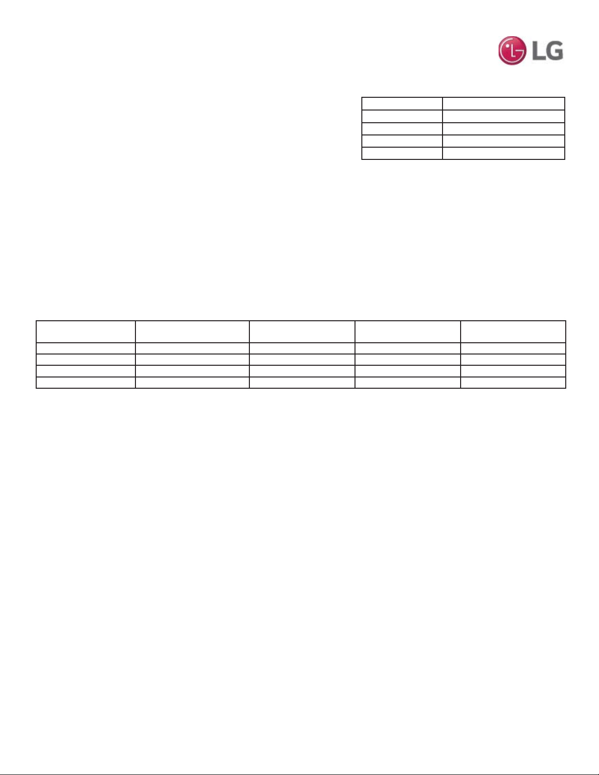
MULTI
F
MAX
MULTI
F
Due to our policy of continuous product innovation, some specifications may change without notification.
©LG Electronics U.S.A., Inc., Englewood Cliffs, NJ. All rights reserved. “LG” is a registered trademark of LG Corp.
MULTI F REFRIGERANT
CHARGE WORKSHEET
LG Multi F outdoor units ship from the factory with a charge of R410A refrigerant. A
trim charge may need to be added to take into account additional piping length.
To determine the additional refrigerant that is needed, apply the formula below,
and record the results. If the total additional refrigerant charge value is a negative
number, then an additional trim charge does not need to be added to the system.
$GGLWLRQDOFKDUJHOEV ,QVWDOOHG/HQJWKRI%UDQFK>$@±&KDUJHOHVV3LSH/HQJWK>/@[D
,QVWDOOHG/HQJWKRI%UDQFK>%@±&KDUJHOHVV3LSH/HQJWK>/@[D
,QVWDOOHG/HQJWKRI%UDQFK>&@±&KDUJHOHVV3LSH/HQJWK>/@[D
,QVWDOOHG/HQJWKRI%UDQFK>'@±&KDUJHOHVV3LSH/HQJWK>/@[D
- CF (Correction Factor) x 5.29
Multi F Outdoor Unit
Model
Min. to Max. Piping Length
for One Branch (ft.)
Max. Total System Piping
Length (ft.)
Chargeless Pipe Length
per Branch (L) (ft.)
Additional Charge Needed
(a) (oz./ft.)
LMU18CHV 10 to 82 164 24.6 0.22
LMU24CHV 10 to 82 246.1 24.6 0.22
LMU30CHV 10 to 82 246.1 24.6 0.22
LMU36CHV 10 to 82 246.1 24.6 0.22
Outdoor Unit Factory Charge lbs. of R410A
LMU18CHV 3.96
LMU24CHV 3.96
LMU30CHV 6.18
LMU36CHV 6.18
Multi F Outdoor Unit Factory Charge
• Number of installed length of branches depends on the specifications of the outdoor unit model.
• &) 0D[LPXPQXPEHURIFRQQHFWLEOHLQGRRUXQLWV±7RWDOQXPEHURIFRQQHFWHGLQGRRUXQLWV
Multi F Outdoor Unit Piping Specifications
BBBBBBBB>$@±[ BBBBBBBB
BBBBBBBB>%@±[ BBBBBBBB
BBBBBBBB>&@±[ BBBBBBBB
BBBBBBBB>'@±[ BBBBBBBB
- ________CF x 5.29 - (________)
= ________ Additional Charge (lbs.)
Multi F Refrigerant Charge Calculations
Multi F Outdoor Unit Additional Refrigerant Charge Formula
Note:
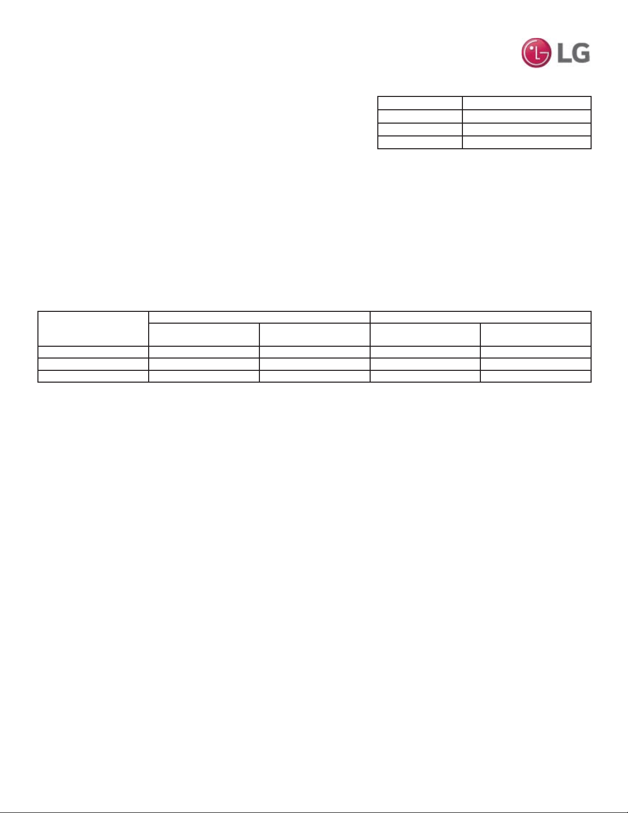
MULTI
F
MAX
MULTI
F
Due to our policy of continuous product innovation, some specifications may change without notification.
©LG Electronics U.S.A., Inc., Englewood Cliffs, NJ. All rights reserved. “LG” is a registered trademark of LG Corp.
Outdoor Unit Model
Main Piping Length Branch Piping Length
Chargeless Pipe Length of
Main Pipe (L) (ft.)
Additional Charge Needed
(a) (oz./ft.)
Chargeless Pipe Length
per Branch Pipe (B) (ft.)
Additional Charge Needed
(b) (oz./ft.)
LMU480HV 16.4 0.54 16.4 0.22
LMU540HV 16.4 0.54 16.4 0.22
LMU600HV 16.4 0.54 16.4 0.22
Multi F MAX Outdoor Unit Piping Specifications
$GGLWLRQDOFKDUJHOEV 7RWDO0DLQ3LSLQJ/HQJWK>$@&KDUJHOHVV3LSH/HQJWKRI0DLQ3LSH>/@[D
,QVWDOOHG/HQJWKRI%UDQFK>%@±&KDUJHOHVV3LSH/HQJWK>%@[E
,QVWDOOHG/HQJWKRI%UDQFK>%@±&KDUJHOHVV3LSH/HQJWK>%@[E
,QVWDOOHG/HQJWKRI%UDQFK>%@±&KDUJHOHVV3LSH/HQJWK>%@[E
- CF (Correction Factor) x 3.53
• Number of installed length of branches depends on system specifications.
• &) 0D[LPXPQXPEHURIFRQQHFWLEOHLQGRRUXQLWV±7RWDOQXPEHURIFRQQHFWHGLQGRRUXQLWV
MULTI F MAX REFRIGERANT
CHARGE WORKSHEET
LG Multi F MAX outdoor units ship from the factory with a charge of R410A refrig-
erant. A trim charge may need to be added to take into account additional piping
length.
To determine the additional refrigerant that is needed, apply the formula below,
and record the results. If the total additional refrigerant charge value is a negative
number, then an additional trim charge does not need to be added to the system.
Outdoor Unit Factory Charge lbs. of R410A
LMU480HV 9.7
LMU540HV 9.7
LMU600HV 12.3
Multi F MAX Outdoor Unit Factory Charge
BBBBBBBB>$@±[ BBBBBBBB
BBBBBBBB>%@±[ BBBBBBBB
BBBBBBBB>%@±[ BBBBBBBB
BBBBBBBB>%@±[ BBBBBBBB
BBBBBBBB>%@±[ BBBBBBBB
BBBBBBBB>%@±[ BBBBBBBB
BBBBBBBB>%@±[ BBBBBBBB
BBBBBBBB>%@±[ BBBBBBBB
BBBBBBBB>%@±[ BBBBBBBB
- ________CF x 3.53 - (________)
= ________ Additional Charge (lbs.)
Multi F MAX Refrigerant Charge Calculations
Note:
Refer to Service Manuals posted on www.lghvac.com for a full description of all error codes and work-arounds.
LG Electronics, U.S.A., Inc.
Commercial Air Conditioning Division
4300 North Point Parkway
Alpharetta, Georgia 30022
www.lg-vrf.com
20001747 ISO 9001: 2008
LG ELECTRONICS INC.
LG Electronics Products Support
1-888-865-3026 USA
Follow the prompts for HVAC products.
IM_MultiF_ODU_4_16
Supersedes: IM_MultiF_ODU_11_15