Loading ...
Loading ...
Loading ...
12
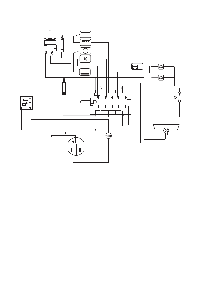
ELECTRIC DIAGRAM
ELECTRIC DIAGRAM KEY
F1 Oven switch
TM Oven thermostat
TL
Thermal overload (normally closed)
I Oven lamp switch
PR Electronic programmer
LF Oven lamps
S1 Thermostat pilot lamp
S2 Line pilot lamp
C Oven top heating element
G Oven grill heating element
S Oven bottom heating element
CIR Oven circular heating element
V Oven fan motor
CF Cooling fan motor
GIR Rotisserie motor
M Terminal block
T Earth connection
1
6
4
93 8
2 7
5 10
1a
6a
4a
9a3a 8a
2a 7a
5a 10a
T
N
L
M
C
G
S
CIR
V
CF
GIR
LF
S2
S1
I
PR
L/N
L/8
LF
F1
TM
TL
Figure 9
Loading ...
Loading ...
Loading ...