Loading ...
Loading ...
Loading ...
035-15857-402
Rev.
B
(0402)
SECTION
C
PAC
SERIES
PACKAGED
AIR
CONDITIONERS
Pre-drilled
screw
holes
are
provided
in
the
control
box.
Using
screws
provided
in
the
kit,
install
the
start
relay
and
start
capacitor
as
shown
in
Figure
5.
NOTE:
When
installing
kits
on
units,
run
wires
through
wiring
clamp
as
shown
in
Figure
5.
On
units
which
have
a
solid-state
start
device;
remove
solid
state
start
device
along
with
the
red
and
brown
wiring
connections
to
run
capacitor.
1.
Attach
the
black
lead
wire
from
the
starting
kit
relay
#5
to
T1
terminal
of
the
contactor.
2.
Attach
the
red
lead
wire
from
the
starting
kit
capac-
itor
to
dual
capacitor
“C”.
3.
Locate
the
brown
wire
connecting
the
dual
capaci-
tor
“HERM”
to
the
S
(start)
terminal
on
the
com-
pressor.
4.
Attach
the
brown
lead
wire
from
the
starting
kit
relay
#2
to
the
same
terminal
on
the
run
capacitor
that
was
located
in
Step
3.
See
Figure
6.
5.
Attach
the
yellow
wire
from
the
starting
kit
relay
#1
to
the
start
capacitor.
NOTE:
The
wiring
of
the
capacitor
and
relay
must
agree
with
Figure
6.
Also,
see
diagram
on
con-
trol
box
cover.
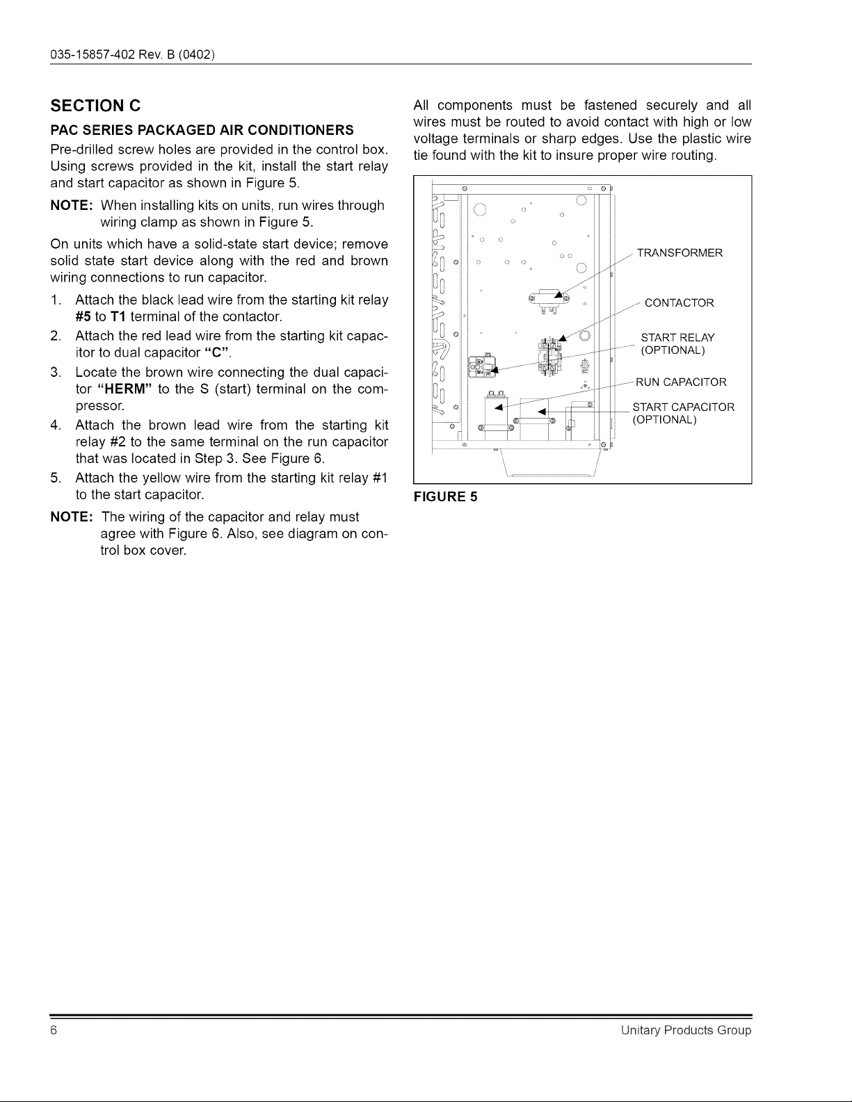
All
components
must
be
fastened
securely
and
_
ail
wires
must
be
routed
to
avoid
contact
with
high
or
low
voltage
terminals
or
sharp
edges.
Use
the
plastic
wire
tie
found
with
the
kit
to
insure
proper
wire
routing.
:
o
8h
a
O
3
~
o
)
6
7.
oo
_-
TRANSFORMER
of)
|
«
A
v
Ka
,
Ss
_>
CONTACTOR
—°
_
START
RELAY
=)
~~
(OPTIONAL)
lo
tn
__-
RUN
CAPACITOR
a
START
CAPACITOR
=
(OPTIONAL)
FIGURE
5
Unitary
Products
Group
Loading ...
Loading ...
Loading ...