Loading ...
Loading ...
Loading ...
ENGLISH - 17
OTHER EQUIPMENT CONNECTIONS
System connections
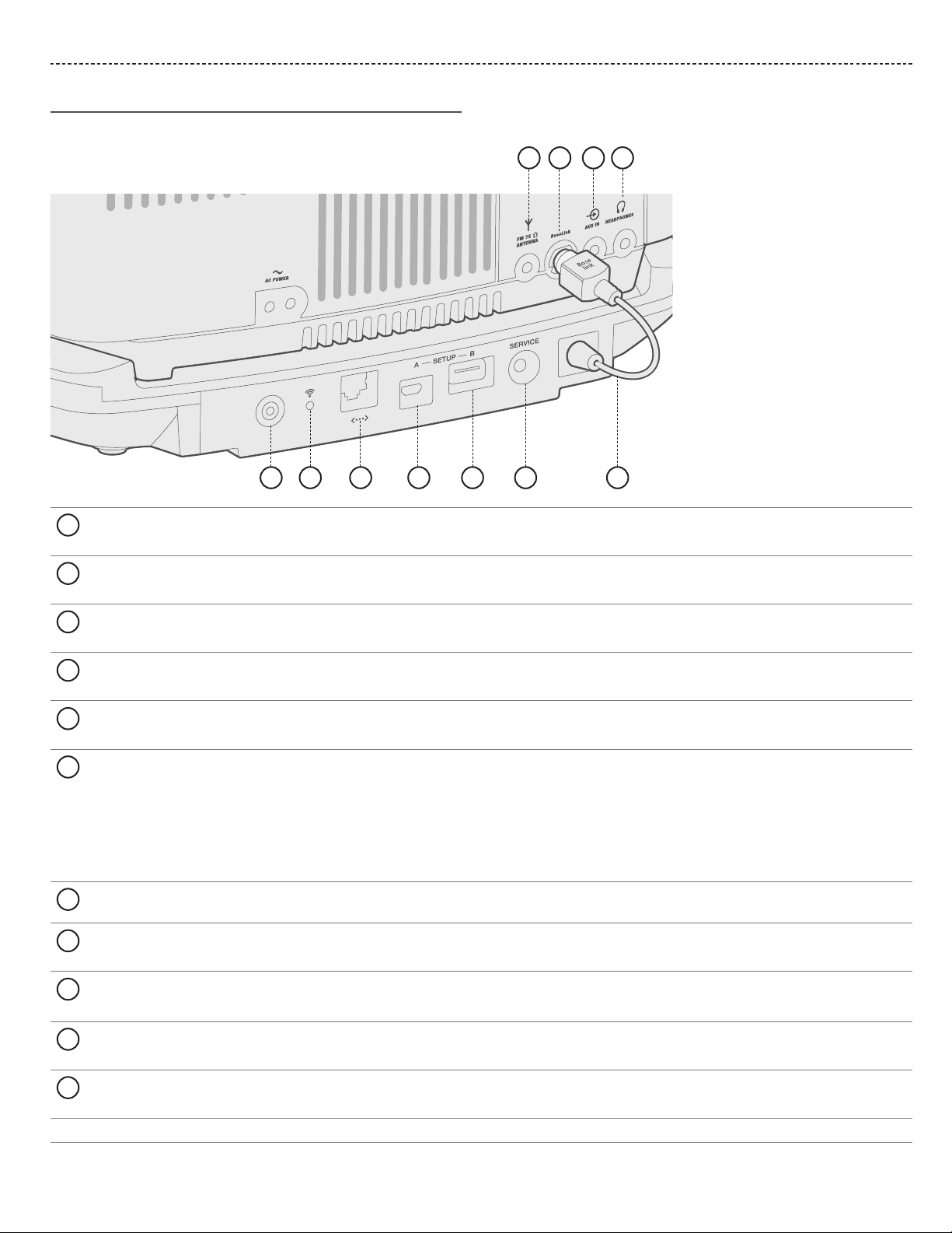
The connector panel provides connections for external equipment.
5
21 3 4
6
7
8
9
10 11
1
ANTENNA
3.5 mm FM antenna (75 ohm) connector (see page 19).
2
BoseLink connector
Input connector for the SoundTouch® pedestal.
3
AUX IN connector
3.5 mm stereo input connector for external sources (see page 18).
4
HEADPHONES
3.5 mm input connector for headphones (see page 18).
5
Control button
Disables Wi-Fi, initiates setup mode or restarts the SoundTouch® pedestal (see page 21).
6
Wi-Fi indicator:
• Blinking white – Searching for Wi-Fi network
• Solid white (dim) – Power-saving mode and connected to Wi-Fi network
• Solid white (bright) – System is on and connected to Wi-Fi network
• Solid amber – System is in setup mode
• O – Wi-Fi networking disabled or system is connected to Ethernet
7
Ethernet connector
Used for a wired network connection.
8
SETUP A
USB Micro-B connector for network setup using a computer.
9
SETUP B
*
USB Standard A connector reserved for future use.
10
SERVICE connector
Used for special service functions. Not for customer use.
11
SoundTouch® pedestal Bose link cable
Plugs into the Bose link connector. It provides power and control signals to the SoundTouch® pedestal.
*
The USB connectors are not designed to charge smartphones, tablets or similar devices.
Loading ...
Loading ...
Loading ...