
Loading ...
Loading ...
Loading ...
SECTION3: ASSEMBLINGYOURSTRINGTRIMMERMOWER
IMPORTANT:This unit is shipped without gasoline or oil
in the engine. Be certain to service engine with gasoline
and oil as instructed in the separate engine manual
before operating your mower.
NOTE: Reference to right or left hand side of the string
trimmer mower is observed from the operating position.
RemovingUnitFromCarton
• Remove staples, break glue on top flaps, or cut
tape at carton end and peel along top flap to open
carton.
• Remove loose parts if included with unit (i.e.,
operator's manual, safety glasses, etc.)
• Cut along corners, lay carton down flat, and remove
packing material.
• Roll or slide unit out of carton and check carton
thoroughly for loose parts.
DisconnectingSparkPlugWire
Before setting up your string trimmer mower,
disconnect the spark plug wire from the spark plug. See
Figure 1.
Stud
o o
Spark
Plug Wire
/ /
_Spark Plug _
IIw're\
Figure 1
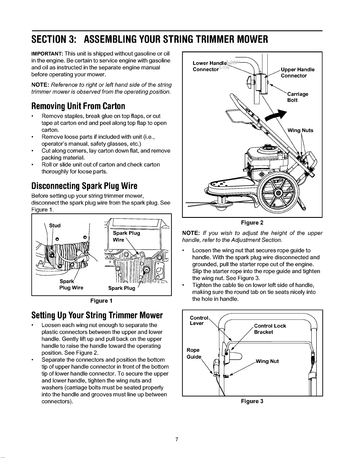
SettingUpYourStringTrimmerMower
• Loosen each wing nut enough to separate the
plastic connectors between the upper and lower
handle. Gently lift up and pull back on the upper
handle to raise the handle toward the operating
position. See Figure 2.
• Separate the connectors and position the bottom
tip of upper handle connector in front of the bottom
tip of lower handle connector. To secure the upper
and lower handle, tighten the wing nuts and
washers (carriage bolts must be seated properly
into the handle and grooves must line up between
connectors).
Connector
Connector
Carriage
Bolt
Figure 2
NOTE: If you wish to adjust the height of the upper
handle, refer to the Adjustment Section.
• Loosen the wing nut that secures rope guide to
handle. With the spark plug wire disconnected and
grounded, pull the starter rope out of the engine.
Slip the starter rope into the rope guide and tighten
the wing nut. See Figure 3.
• Tighten the cable tie on lower left side of handle,
making sure the round tab on tie seats nicely into
the hole in handle.
Control_ f
Lever _ CrorltkOltLock
Figure 3
Loading ...
Loading ...
Loading ...