Loading ...
Loading ...
Loading ...
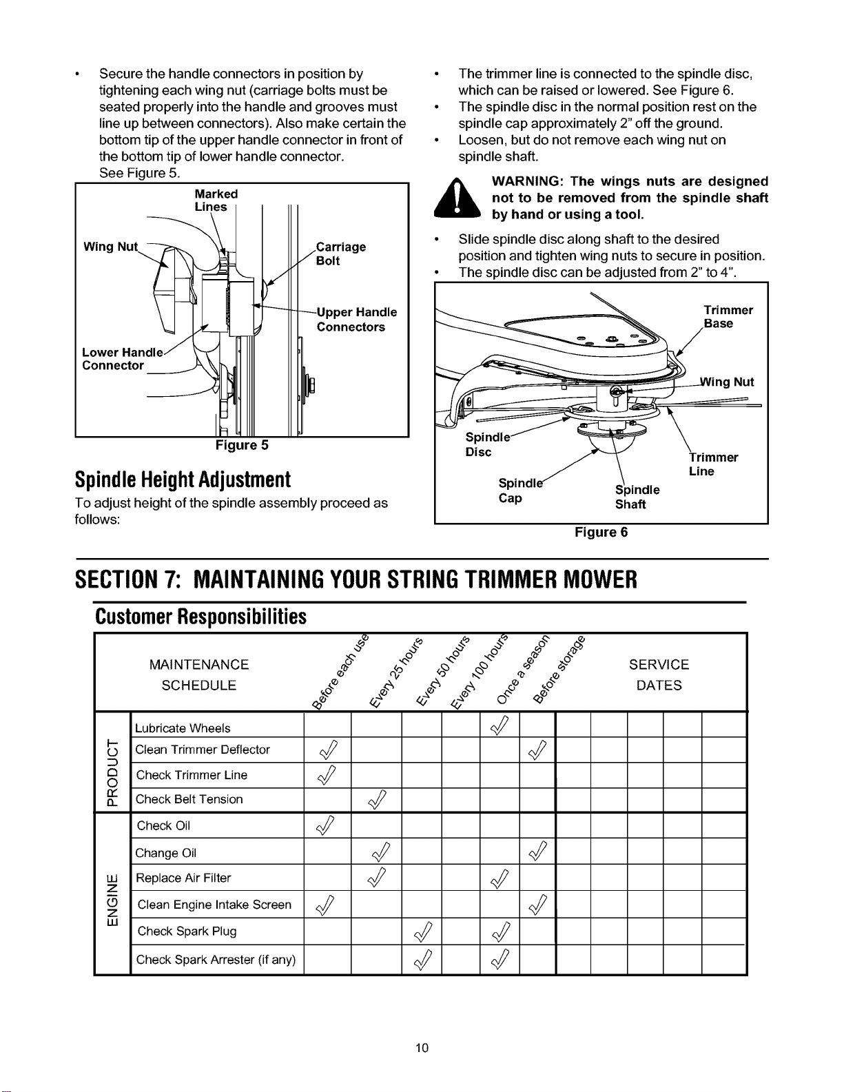
Securethehandleconnectorsinpositionby
tighteningeachwingnut(carriageboltsmustbe
seatedproperlyintothehandleandgroovesmust
lineupbetweenconnectors).Alsomakecertainthe
bottomtipoftheupperhandleconnectorinfrontof
thebottomtipoflowerhandleconnector.
SeeFigure5.
Marked
Lines
Wing Nut
jCarriage
Bolt
Lower
Connector
Connectors
° The trimmer line is connected to the spindle disc,
which can be raised or lowered. See Figure 6.
° The spindle disc in the normal position rest on the
spindle cap approximately 2" off the ground.
° Loosen, but do not remove each wing nut on
spindle shaft.
WARNING: The wings nuts are designed
not to be removed from the spindle shaft
by hand or using a tool.
° Slide spindle disc along shaft to the desired
position and tighten wing nuts to secure in position.
° The spindle disc can be adjusted from 2" to 4".
Trimmer
Base
Nut
Figure 5
Spindle HeightAdjustment
To adjust height of the spindle assembly proceed as
follows:
Sl
Disc
S_ >indle
Cap Shaft
Figure 6
Trimmer
Line
SECTION7: MAINTAININGYOURSTRINGTRIMMERMOWER
CustomerResponsibilities
MAINTENANCE _°_'_' _"°"_ ._'_'°"__'_'°'_ _'_e°_"_--°''_
SCHEDULE e_o,P .._<_ ,_o_ ._ O_.Oo<_o
LubricateWheels R_
b Clean Trimmer Deflector R_
8 CheckTrimmer Line _:_
n_ Check Belt Tension
Check Oil R_
Change Oil _
LU ReplaceAir Filter _ R_
Z
_z Clean Engine IntakeScreen R_ R_
I.U
Check Spark Plug <_
CheckSpark Arrester (if any) _
SERVICE
DATES
10
Loading ...
Loading ...
Loading ...