Loading ...
Loading ...
Loading ...
7 Elkay Manufacturing Company
(630) 574-8484
1000005232 (
Rev. B - 05/19) Built-in Filtered Water Dispenser
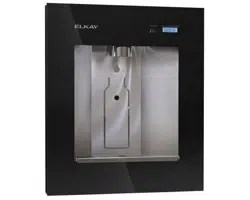
4.4 Mounting Height Dimensions
1. The suggested water dispenser mounting height to the
center of the water dispenser sensor (D) is 47 inches
(1194 mm). This height can be adjusted higher or
lower depending on the desires of the user.
A
B
D
C
1
2
3
A
Wall Opening Dimensions
1) P-trap. 2) 3/8 inch exible water tubing. (3) Electrical box.
Wall Opening Dimensions
A) 14-1/2 inches (368 mm) wall opening.
.
Unit Height (from oor)
B) 55-3/4 inches (1441 mm). C) 47 inches (1194 mm).
Rough-in Reference Dimensions
D) 21-1/8 inches (537 mm) centerline of lter water inlet.
Note Item 1: If the p-trap is sealed within the wall, under
the water dispenser, all the plumbing
joints must be glued. The glue must be
appropriate for the PVC pipe utilized. If the
p-trap uses threaded components, they
must be easily accessible.
Note Item 2: According to most electrical codes, the
electrical box cannot be sealed inside a
wall cavity with no access. If the electrical
connection is placed under the unit, a
user-supplied removable wall cover will be
required to access the junction box.
4.5 Water Dispenser Installation
There are several installation options available:
• Water dispenser with attached lter box and lter.
• Water dispenser with a remote lter.
Note: When the lter is located in a remote location,
mount the lter vertically on a wall or other supporting
structure.
• Water dispenser with remote lter and chiller.
Note: When the lter is located in a remote location,
mount the lter vertically on a wall or other supporting
structure before the water chiller.
• Water dispenser with optional waste drain.
Use the following sections to install the water dispenser
using the appropriate conguration.
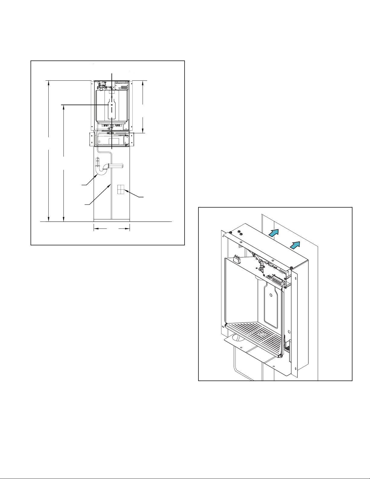
4.5.1 Installing Water Dispenser into the Wall
1. Cut the opening into the wall using the suggested
mounting dimensions as a guide.
2. Place the unit into the wall cavity and slide it up
against the drywall at the top of the opening. The
unit is designed with 1/4 inch overlap to conceal any
irregularities at the top of the wall opening.
Loading ...
Loading ...
Loading ...