Loading ...
Loading ...
Loading ...
11
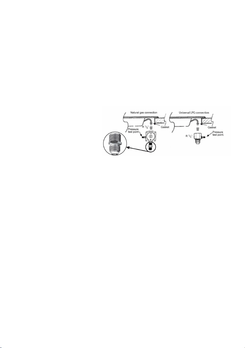
Fit regulator (N.G.) or a test point (Universal LPG) directly
to the R 1/2’’ connection as per Fig. 5. and Fig. 6.
Direction of gas flow is indicated on the rear of the regulator.
For position of the inlet connection refer Fig.1.
Use pipe compound or thread sealant, properly theaded
pipes and careful assembly procedure so that there is no
cross threading, etc., which might cause damage or
leakage.
Make sure that all connections peformed are free of
leakage.
The manufacturer does not accept any liability for
leakage on connections performed by the installer or if
the L-tube is moved or twisted.
There are two ways to carry out the connection to the
main gas line:
A. The hotplate can be connected with rigid pipe as
specified in AS/NZS 5601.1
B. Flexible Hose: If installing with a hose assembly, install
with a hose assembly that complies with AS/NZS 1869
(AGA Approved), 10 mm ID, class Bor D, no more than
1,2 m long and in accordance with AS/NZS 5601.1.
Ensure that the hose does not contact the hot surfaces of
the hotplate, oven, dishwasher or any other appliance that
may be installed underneath or next to the hotplate. The
hose should not be subjected to abrasion, kinking or
permanent deformation and should be able to be
inspected along its entire length with the cooktop in the
installed position. Unions compatible with the hose fittings
must be used and all connections tested for gas leaks.
The supply connection point shall be accessible with the
appliance installed.
WARNING: Ensure that the hose assembly is restrained
from accidental contact with the flue outlet of an
underbench oven.
Before Leaving- Check all connections for gas leaks with
soap and water. DO NOT use a naked flame for detecting
leaks. Ignite all burners both individually and concurrently
to ensure correct operation of gas valves, burners and
ignition. Turn gas taps to low flame position and observe
stability of the flame for each burner individually and all
together. Adhere the duplicate data plate to an
Fig. 5 Fig. 6
Loading ...
Loading ...
Loading ...