
230V
B E LT LINISHER &
SUPPORT COLUMN
98421 & 98422
These instructions accompanying the product are the original instructions. This document is part of the product,
keep it for the life of the product passing it on to any subsequent holder of the product. Read all these instructions
before assembling, operating or maintaining this product.
This manual has been compiled by Draper Tools describing the purpose for which the product has been designed,
and contains all the necessary information to ensure its correct and safe use. By following all the general safety
instructions contained in this manual, it will ensure both product and operator safety, together with longer life of the
product itself.
All photographs and drawings in this manual are supplied by Draper Tools to help illustrate the operation of the
product.
Whilst every effort has been made to ensure the accuracy of information contained in this manual, the Draper Tools
policy of continuous improvement determines the right to make modifications without prior warning.

1.1 INTRODUCTION:
USER MANUAL FOR: 230V Belt Linisher and Support Column
Stock Nos: 98421 & 98422
Part No: BL1500D & ABL1500D
1.2 REVISION HISTORY:
Date first published June 2020.
As our user manuals are continually updated, users should make sure that they use the very latest
version.
Downloads are available from: http://drapertools.com/manuals
Draper Tools Limited
Hursley Road
Chandler’s Ford
Eastleigh
Hampshire
SO53 1YF
UK
Website: drapertools.com
Product help line: +44 (0) 23 8049 4344
General Fax: +44 (0) 23 8026 0784
1.3 UNDERSTANDING THIS MANUAL’S SAFETY CONTENT:
Warning! – Information that draws attention to the risk of injury or death.
Important – Information that draws attention to the risk of damage to the product or surroundings.
1.4 COPYRIGHT © NOTICE:
Copyright © Draper Tools Limited.
Permission is granted to reproduce this publication for personal and educational use only.
Commercial copying, redistribution, hiring or lending is prohibited.
No part of this publication may be stored in a retrieval system or transmitted in any other form or
means without written permission from Draper Tools Limited.
In all cases this copyright notice must remain intact.
1. TITLE PAGE
– 2 –

2. CONTENTS
– 3 –
2.1 TABLE OF CONTENTS
1. TITLE PAGE
1.1 INTRODUCTION .......................................................................................................... 2
1.2 REVISION HISTORY ................................................................................................... 2
1.3 UNDERSTANDING THIS MANUAL’S SAFETY CONTENT: ........................................ 2
1.4 COPYRIGHT © NOTICE: ............................................................................................. 2
2. CONTENTS
2.1 TABLE OF CONTENTS ............................................................................................... 3
3. WARRANTY
3.1 WARRANTY ................................................................................................................. 5
4. INTRODUCTION
4.1 SCOPE ......................................................................................................................... 6
4.2 SPECIFICATION .......................................................................................................... 6
4.3 HANDLING AND STORAGE ........................................................................................ 6
5. HEALTH AND SAFETY INFORMATION
5.1 GENERAL SAFETY INSTRUCTIONS FOR POWER TOOL USE ............................... 7
5.2 ADDITIONAL SAFETY INSTRUCTIONS FOR ABRASIVE FINISHING MACHINES .. 8
5.3 RESIDUAL RISK .......................................................................................................... 9
5.4 CONNECTION TO THE POWER SUPPLY.................................................................. 9
6. TECHNICAL DESCRIPTION
6.1 IDENTIFICATION ....................................................................................................... 10
7. UNPACKING AND CHECKING
7.1 PACKAGING .............................................................................................................. 11
7.2 WHAT’S IN THE BOX ................................................................................................ 11
8. ASSEMBLY INSTRUCTIONS
8.1 SUPPORT COLUMN (98422 ONLY) ......................................................................... 12
8.2 INSTALLATION .......................................................................................................... 12
8.3 EYE SHEILD .............................................................................................................. 13
8.4 SPARK TRAP ............................................................................................................. 13
8.5 WORK REST ............................................................................................................. 13
9. OPERATION AND USE
9.1 REPLACING BELTS .................................................................................................. 14
9.2 ADJUSTING BELT TRACKING .................................................................................. 14
9.3 FLAT GRINDING ........................................................................................................ 15
9.4 END GRINDING ......................................................................................................... 15
9.5 SAFETY NO VOLT SWITCH ...................................................................................... 15
10. MAINTENANCE & TROUBLESHOOTING
10.1 MAINTENANCE ......................................................................................................... 16
10.2 TROUBLESHOOTING ............................................................................................... 16

2. CONTENTS
– 4 –
11. DISPOSAL
12.1 DISPOSAL ................................................................................................................. 18
12. EXPLANATION OF SYMBOLS
13.1 EXPLANATION OF SYMBOLS .................................................................................. 19

3. WARRANTY
– 5 –
3.1 WARRANTY
Draper tools have been carefully tested and inspected before shipment and are guaranteed to be
free from defective materials and workmanship.
Should the tool develop a fault, please return the complete tool to your nearest distributor or
contact:
Draper Tools Limited, Chandler’s Ford, Eastleigh, Hampshire, SO53 1YF. England.
Telephone Sales Desk: (023) 8049 4333 or Product Help Line (023) 8049 4344.
A proof of purchase must be provided with the tool.
If upon inspection it is found that the fault occurring is due to defective materials or workmanship,
repairs will be carried out free of charge. This warranty period covering parts and labour is 12
months from the date of purchase except where tools are hired out when the warranty period is 90
days from the date of purchase. This is extended to 24 months for parts only. This warranty does
not apply to any consumable parts, any type of battery or normal wear and tear, nor does it cover
any damage caused by misuse, careless or unsafe handling, alterations, accidents, or repairs
attempted or made by any personnel other than the authorised Draper warranty repair agent.
Note: If the tool is found not to be within the terms of warranty, repairs and carriage charges will
be quoted and made accordingly.
This warranty applies in lieu of any other warranty expressed or implied and variations of its terms
are not authorised.
Your Draper warranty is not effective unless you can produce upon request a dated receipt or
invoice to verify your proof of purchase within the warranty period.
Please note that this warranty is an additional benefit and does not affect your statutory rights.
Draper Tools Limited.

4. INTRODUCTION
4.1 SCOPE
This machine is used to smooth a workpiece, creating a level, even surface. It can also be used to
polish materials. Any application other than that it was designed for is considered misuse.
4.2 SPECIFICATION
Stock no.. .................................................................................................................................. 98421
Part no. ............................................................................................................................... BL1500D
Rated voltage ............................................................................................................................230V
Rated frequency .........................................................................................................................50Hz
Rated input .............................................................................................................................1500W
Revolutions per minute (no load) ....................................................................................... 2800min-1
Belt size ...................................................................................................................... 100 x 1220mm
Belt speed ................................................................................................................................. 19M/s
Sound pressure level .......................................................................................................... 81.7dB(A)
Sound power level .............................................................................................................. 94.5dB(A)
Weight ........................................................................................................................................ 26kg
4.3 HANDLING AND STORAGE
– Care must be taken when handling this product. Dropping this power tool could have an effect
on its accuracy and could also result in personal injury. This product is not a toy and must be
respected.
– Environmental conditions can have a detrimental effect on this product if neglected. Exposure
to damp air can gradually corrode components. If the product is unprotected from dust and
debris, components will become clogged. If not cleaned and maintained correctly or regularly,
the machine will not perform at its best.
– 6 –

5. HEALTH AND SAFETY INFORMATION
5.1 GENERAL SAFETY INSTRUCTIONS FOR POWER TOOL USE
When using any type of power tool there are steps that should be taken to make sure that you, as
the user, remain safe.
Common sense and a respect for the tool will help reduce the risk of injury.
Read the instruction manual fully. Do not attempt any operation until you have read and
understood this manual.
Most important you must know how to safely start and stop this machine, especially in an
emergency.
Keep the work area tidy and clean. Attempting to clear clutter from around the machine during
use will reduce your concentration. Mess on the floor creates a trip hazard. Any liquid spilt on the
floor could result in you slipping.
Find a suitable location. If the machine is bench mounted, the location should provide good
natural light or artificial lighting as a replacement. Avoid damp and dust locations as it will have a
negative effect on the machine’s performance. If the machine is portable do not expose the tool to
rain. In all cases do not operate power tools near any flammable materials.
Keep bystanders away. Children, onlookers and passers by must be restricted from entering the
work area for their own protection. The barrier must extend a suitable distance from the tool user.
Unplug and house all power tools that are not in use. A power tool should never be left unattended
while connected to the power supply. They must be housed in a suitable location, away locked up
and from children. This includes battery chargers.
Do not overload or misuse the tool. All tools are designed for a purpose and are limited to what
they are capable of doing. Do not attempt to use a power tool (or adapt it in any way) for an
application it is not designed for. Select a tool appropriate for the size of the job. Overloading a tool
will result in tool failure and user injury. This covers the use of accessories.
Dress properly. Loose clothing, long hair and jewellery are all dangerous because they can
become entangled in moving machinery. This can also result in parts of body being pulled into the
machine. Clothing should be close fitted, with any long hair tired back and jewellery and neck ties
removed. Footwear must be fully enclosed and have a non-slip sole.
Wear personal protective equipment (PPE). Dust, noise, vibration and swarf can all be
dangerous if not suitably protected against. If the work involving the power tool creates dust or
fumes wear a dust mask. Vibration to the hand, caused by operating some tools for longer periods
must be protected against. Wear vibration reducing gloves and allow long breaks between uses.
Protect against dust and swarf by wearing approved safety goggles or a face shield. These are
some of the more common hazards and preventions, however, always find out what hazards are
associated with the machine/work process and wear the most suitable protective equipment
available.
Do not breathe contaminated air. If the work creates dust or fumes connect the machine (if
possible) to an extraction system either locally or remotely. Working outdoors can also help if
possible.
Move the machine as instructed. If the machine is hand held, do not carry it by the power supply
cable. If the product is heavy, employ a second or third person to help move it safely or use a
mechanical device. Always refer to the instructions for the correct method.
Do not overreach. Extending your body too far can result in a loss of balance and you falling. This
could be from a height or onto a machine and will result in injury.
Maintain your tools correctly. A well maintained tool will do the job safely. Replace any damaged
or missing parts immediately with original parts from the manufacturer. As applicable, keep blades
sharp, moving parts clean, oiled or greased, handles clean, and emergency devices working.
Wait for the machine to stop. Unless the machine is fitted with a safety brake, some parts may
continue to move due to momentum. Wait for all parts to stop, then unplug it from the power supply
– 7 –

5. HEALTH AND SAFETY INFORMATION
before making any adjustments, carrying out maintenance operations or just finishing using the
tool.
Remove and check setting tools. Some machinery requires the use of additional tools or keys to
set, load or adjust the power tool. Before starting the power tool always check to make certain they
have been removed and are safely away from the machine.
Prevent unintentional starting. Before plugging any machine in to the power supply, make sure
the switch is in the OFF position. If the machine is portable, do not hold the machine near the
switch and take care when putting the machine down, that nothing can operate the switch.
Carefully select an extension lead. Some machines are not suitable for use with extension
leads. If the tool is designed for use outdoors, use an extension lead also suitable for that
environment. When using an extended lead, select one capable of handling the current (amps)
drawn by the machine in use. Fully extend the lead regardless of the distance between the power
supply and the tool. Excess current (amps) and a coiled extension lead will both cause the cable to
heat up and can result in fire.
Concentrate and stay alert. Distractions are likely to cause an accident. Never operate a power
tool if you are under the influence of drugs (prescription or otherwise), including alcohol or if you
are feeling tired. Being disorientated will result in an accident.
Have this tool repaired by a qualified person. This tool is designed to conform to the relevant
international and local standards and as such should be maintained and repaired by someone
qualified, using only original parts supplied by the manufacturer. This will ensure the tool remains
safe to use.
5.2 ADDITIONAL SAFETY INSTRUCTIONS FOR ABRASIVE FINISHING
MACHINES
WARNING: Failure to follow these rules may result in serious personal injury.
Don’t operate the machine until it is assembled and installed according to the instructions.
Obtain training from the supervisor, instructor, or another qualified person if you are not familiar
with the operation of this machine.
Follow all technical requirements and recommended electrical connections.
Use the guards whenever possible. Check to see that they are in place, secured and working
correctly.
Check the belt for wear and tension. If the belt is damaged or can’t be tensioned properly, replace it.
Check for correct belt installation and ensure that the belt is tracking properly.
Keep arms, hands and fingers away from abrasive surfaces.
Avoid awkward operations and hand positions where a sudden slip could cause a hand to contact
the sanding surface.
Never wear gloves or hold the workpiece with a rag when sanding.
Never start the machine with the workpiece against the sanding surface.
Never start the machine before clearing all objects (tools, scrap pieces, etc.) from the machine.
Maintain minimum clearance between the table and the sanding surface.
Use a backstop when using the belt finishing machine in a horizontal position.
Feed the workpiece against the rotation of the sanding surface. Hold the workpiece securely on
the table.
Use a dust collection system. Or at least wear the mask during operation.
Clean the machine and dust collection system thoroughly before and after sanding metal.
– 8 –

Do not sand workpieces shorter than 70mm or thinner than 1mm.
Properly support long or wide workpieces.
Disconnect the machine from the power source before installing or removing accessories, before
adjusting or changing set-ups, or when repairing.
Disconnect the machine from the power source and clean the table/work area before leaving the
machine. Lock the switch in the ‘OFF’ position to prevent unauthorised use.
The belt linisher is mainly used to conduct surface polishing and grinding of metal, so as to
enhance the roughness and glossiness of spare parts surface. It enjoys high efficiency and
superior performance in grinding. It is an ideal substitute for polishing machines.
This machine is only used for general metals grinding within the range of grinding capacity. Metals
with low ignition points such as magnesium, etc., are prohibited to be machined.
5.3 RESIDUAL RISK
Important: Although the safety instructions and operating manuals for our tools contain extensive
instructions of safe working with power tools, every power tool involves a certain residual risk
which can not be completely excluded by safety mechanisms. Power tools must therefore always
be operated with caution!
5.4 CONNECTION TO THE POWER SUPPLY
Caution: Risk of electric shock. Do not open.
This appliance is supplied with a moulded 3 pin mains plug for your safety. The value of the fuse
fitted is marked on the pin face of the plug. Should the fuse need replacing, ensure the substitute
is of the correct rating, approved to BS1362 and ASTA or BS Kite marked.
ASTA
BSI
The fuse cover is removable with a small plain slot screwdriver. Ensure the fuse cover is replaced
before attempting to connect the plug to an electrical outlet. If the cover is missing, a replacement
must be obtained or the plug replaced with a suitable type.
If a replacement plug is to be fitted this must be carried out by a qualified electrician.
The damaged or incomplete plug, when cut from the cable should be disabled to prevent
connection to a live electrical outlet.
This appliance is Class I
†
and is designed for connection to a power supply matching that detailed
on the rating label and compatible with the plug fitted.
If an extension lead is required, use an approved and compatible lead rated for this appliance.
Follow all the instructions supplied with the extension lead.
†
Earthed
: This product requires an earth connection to protect against electric shock from
accessible conductive parts in the event of failure if the basic insulation.
Important: On products exceeding 2000W it is recommended that the power cable and/or
extension cable are fully unwound before a connection is made to the power supply.
However, ensure the residual cable does not pose a trip hazard.
– 9 –
5. HEALTH AND SAFETY INFORMATION
6. TECHNICAL DESCRIPTION
– 10 –
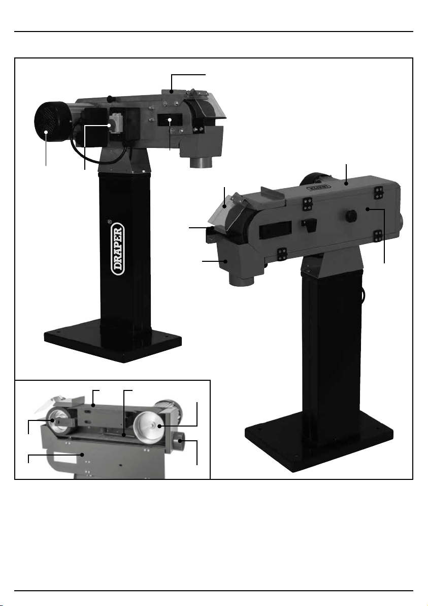
6.1 IDENTIFICATION
(1) Motor.
(2) On/Off buttons & emergency stop switch.
(3) Work stop.
(4) Work rest.
(5) Belt tracking adjustment knob.
(6) Spark trap.
(7) Eye sheild.
(8) Belt guard.
(9) Belt access panel.
(10) Contact wheel.
(11) Platen.
(12) Belt tension lever.
(13) Drive wheel.
(14) Dust extraction outlet.
(10)
(9)
(9)
(14)
(13)
(3)
(11) (12)
(8)
(7)
(6)
(4)
(1)
(5)
(2)
7.1 PACKAGING
Carefully remove the product from the packaging and examine it for any sign of damage that may
have happened during shipping. Lay the contents out and check them against the parts shown
below. If any part is damaged or missing, please contact the Draper Help Line (the telephone
number appears on the Title page) and do not attempt to use the product.
The packaging material should be retained at least during the warranty period, in case the
machine needs to be returned for repair.
Warning!
− Some of the packaging materials used may be harmful to children. Do not leave any of these
materials in the reach of children.
− If any of the packaging is to be thrown away, make sure they are disposed of correctly,
according to local regulations.
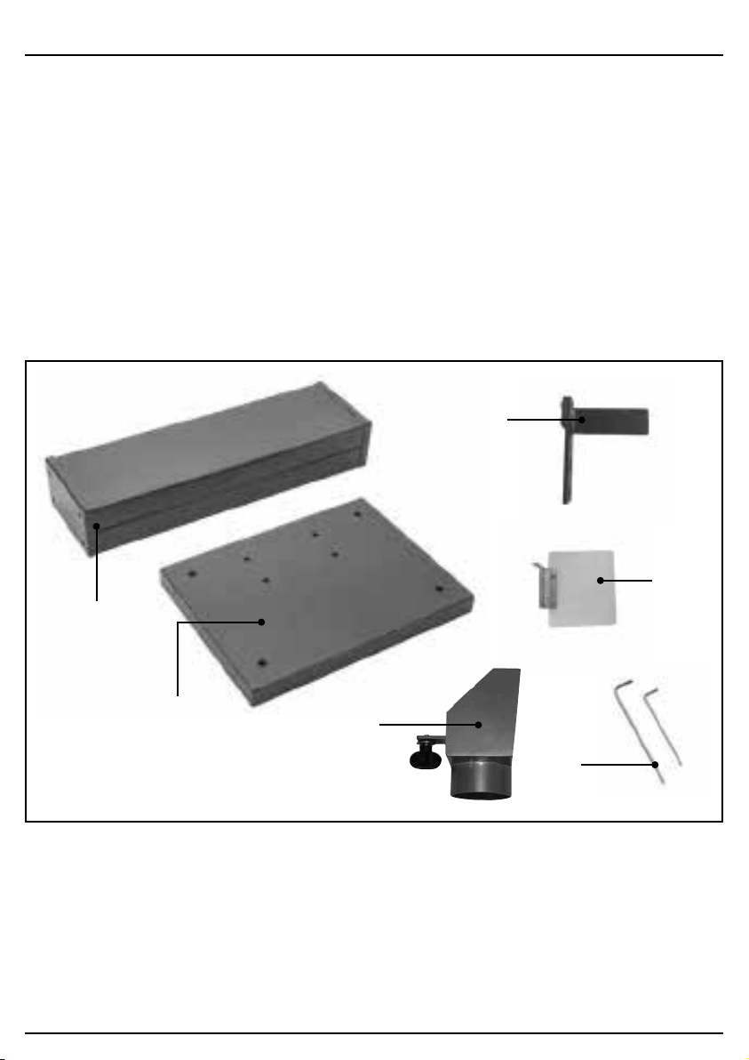
7.2 WHAT’S IN THE BOX
As shown below, there are several parts that do not come fitted or attached to the main machine.
7. UNPACKING AND CHECKING
– 11 –
(4) Work rest.
(6) Spark trap.
(7) Eye shield.
(15) Column (sold separately)
(16) Base.
(17) Hex wrenches: 4, 5mm.
(15)
(6)
(4)
(17)
(16)
(7)
1 FIG.
FIG.2
FIG.3
– 12 –
8. ASSEMBLY INSTRUCTIONS
Note: This machine must be fully assembled
before it can be operated. Before beginning the
assembly process, please make sure you have
read and understood the instructions.
Caution! Some components of this machine are
heavy. Get lifting help to move heavy items to
avoid injury.
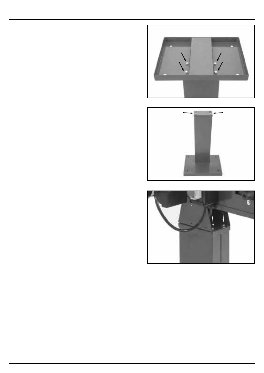
8.1 SUPPORT COLUMN (98422
ONLY) – FIGS.1 - 3
The machine is packaged attached to the
rectangular floor base, but a support column is
available separately under Draper Stock No.
98422.
To install the column:
– Remove the four nuts, bolts and washers in the
base to separate from the machine.
– Position the column upside down and attach
the base with the nuts, bolts and washers
removed in the previous step. Then position
right side up.
– Remove the four bolts and washers from the
top of the column.
– Position machine on top of column and attach
using the fasteners removed in previous step.
8.2 INSTALLATION
Before the machine can be used, a suitable
location must be found. The area must be flat, level
and be able to comfortably accommodate the
weight of this machine and any workpieces.
The area must also be well lit and provide
adequate space around the machine.
Areas liable to excess dust, moisture and direct
sunlight should be avoided.
Note: Before first use - follow the initial starting
instruction and remove any anti-rust protection
which have been applied for transportation.
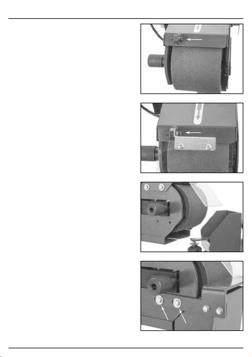
8.3 EYE SHIELD – FIGS.4 - 5
To install the eye shield:
– Remove the cap screw and washer shown in
Fig. 4.
– Install the eye shield with the fastener just
removed.
– Remove the protective covering.
8.4 SPARK TRAP – FIG.6
To install the spark trap:
– Install the spark trap into the slot beneath the
contact wheel.
– Tighten the knob to secure position.
8.5 WORK REST – FIG.7
To install the work rest:
– Remove the two bolts and washers already
installed into the work rest.
– Position the work rest in place and install using
fixings just removed.
– 13 –
8. ASSEMBLY INSTRUCTIONS
FIG.4
FIG.5
FIG.6
FIG.7
– 14 –
9. OPERATION & USE
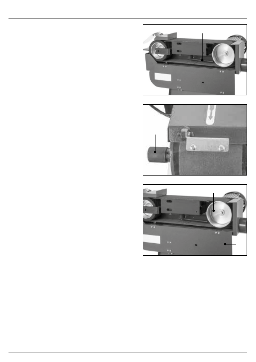
9.1 REPLACING BELT – FIG.8
Warning! Never attempt to adjust, maintain or
service this machine while it is connected to the
power supply.
To replace the belt:
– Open the belt access panel.
– Pull belt tension release lever (12)out to
release the tension of the belt. The lever will
snap into position.
– Removing the old sanding belt from the wheels.
– Place new sanding belt on wheels, then push
the belt tension lever in to tension the belt.
Note: Make sure arrow on inside of sanding
belt points in the same direction as the belt
rotation arrow marked on the machine.
– Rotate belt by hand to make sure the belt
moves freely without rubbing against any parts
of the machine.
– Check and adjust belt tracking (see section 9.2).
9.2 ADJUSTING BELT TRACKING –
FIGS.9 - 10
The purpose of belt tracking is to make sure the
belt stays centered on the wheels and platen
during grinding operations. It needs to be checked
any time you change or replace the belt.
Warning! Never attempt to adjust, maintain or
service this machine while it is connected to the
power supply.
To check and adjust the belt tracking:
– Open the belt access panel.
– Standing at the rear of the machine, rotate the
drive wheel (13)with one hand and watch how
the belt tracks:
- If the belt moves towards the motor (or the
front of the machine) rotate the tracking knob
(5) clockwise.
- If the belt moves away from the motor (or
towards the back of the machine) rotate the
tracking knob (5)anti-clockwise.
– Repeat the test after adjustment to make sure it
is now tracking centrally. Once central close the
belt access panel (9).
– Connect the machine to the power source and
turn it ON. Visually check that the belt is
tracking correctly in the centre of the platen
and wheels, and fine-tune any tracking as
necessary.
FIG.8
FIG.9
FIG.10
(13)
(9)
(5)
(12)
– 15 –
9. OPERATION & USE
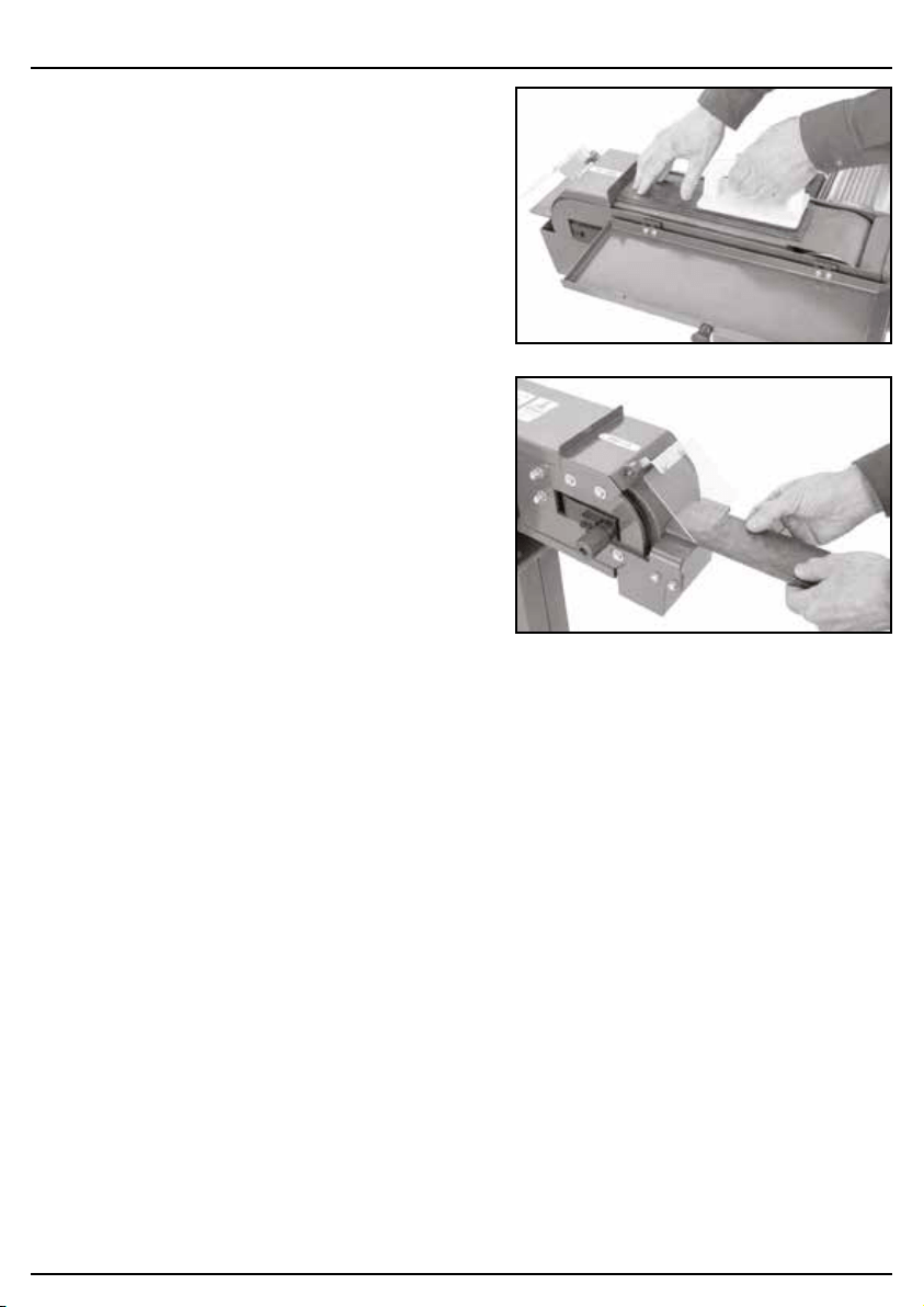
9.3 FLAT GRINDING – FIG.11
Flat grinding operations can be performed directly
on the belt against the platen. Always use two
hands to control the workpiece and use the work
stop to support it.
– Connect the machine to the power supply, turn
it ON and allow it to reach full speed.
– While supporting the workpiece against the
work stop, slowly feed it into moving belt with
light even pressure. Use a push block to
maintain control of the workpiece. DO NOT
force the workpiece against the belt.
Caution! The moving belt can cause serious
personal injury if it comes in contact with fingers,
hands or other body parts. Use extreme care to
provide a safe distance between the belt and any
part of your body.
9.4 END GRINDING – FIG.12
End grinding operations are performed on the front
end of the grinder with the workpiece pressing
against the contact wheel. For additional control
over the workpiece, use the work rest to support
workpieces during operations. Always use two
hands to maintain best control.
– Connect the machine to the power supply, turn
it ON and allow it to reach full speed.
– Position workpiece on work rest if feasible.
– Use both hands to maintain control of the
workpiece and slowly feed it into the contact
wheel at the end of the moving belt, with light,
even pressure. DO NOT force the workpiece
against the belt.
Caution! The moving belt can cause serious
personal injury if it comes in contact with fingers,
hands or other body parts. Use extreme care to
provide a safe distance between the belt and any
part of your body.
9.5 SAFETY NO VOLT SWITCH
This machine is fitted with a safety ‘no volt switch’.
Lift cap to access standard on and off switch, if the
no volt stop button has been used to stop the
machine.
FIG.11
FIG.12

10.1 MAINTENANCE
To minimize your risk of injury and maintain proper machine operation, shut down the machine
immediately if you ever observe any loose bolts, worn or damaged wires, or any other unsafe
conditions, and fix the problem before continuing operations.
After each use check for loose bolts, or a worn or damaged belt. Also make sure you clean any
shavings and dust from all parts of the machine, and empty the spark trap. To empty the spark trap
simply loosen the knob, and slide the trap out. Never use compressed air to blow away dust as
airborne particles may be combustible. Avoid storing metal dust near heat or anything likely to
produce sparks, as some types of metal dust can be flammable.
Regular inspection and cleaning reduces the necessity for maintenance operations and will keep
your tool in good working condition.
The motor must be correctly ventilated during tool operation. Avoid blocking the air inlets and
vacuum the ventilation slots regularly.
10.2 TROUBLESHOOTING
Problem Possible Cause Remedy
Motor does not start, or
power supply trips
immediately after start up.
1. Emergency stop button
depressed/at fault.
1. Lift switch cover. Press
ON button.
2. Incorrect power supply
voltage or circuit size.
2. Ensure correct power
supply voltage and circuit
size are used.
3. Power supply breaker
tripped or fuse blown.
3. Ensure circuit is sized
correctly and free of
shorts. Reset breaker or
replace fuse.
4. Start capacitor at fault. 4. Test/replace if at fault.
5. Wiring broken,
disconnected or corroded.
5. Fix broken, disconnected
or corroded connections.
6. ON/OFF switch at fault. 6. Test/replace ON/OFF
switch.
7. Motor at fault. 7. Test/repair/replace.
Machine stalls or is
underpowered.
1. Excessive feed pressure
applied.
1. Reduce feed pressure.
2. Machine undersized for
task.
2. Reduce workpiece
pressure.
3. Motor overwhelmed. 3. Clean motor, let cool, and
reduce workload.
4. Motor bearings at fault. 4. Test/repair/replace.
5. Motor at fault. 5. Test/repair/replace.
– 16 –
10. MAINTENANCE AND TROUBLESHOOTING

10. MAINTENANCE AND TROUBLESHOOTING
– 17 –
Problem Possible Cause Remedy
Machine has vibration or
noisy operation.
1. Grinding belt not tracking
correctly on wheels.
1. Ensure belt is tracking
correctly.
2. Motor or component
loose.
2. Replace damaged or
missing bolts/nuts or
tighten if loose.
3. Stand not stable or
incorrectly secured to
floor.
3. Tighten mounting
hardware/relocate.
4. Motor fan rubbing on fan
cover.
4. Fix/replace fan cover.
Replace loose/damaged
fan.
5. Motor bearings at fault. 5. Test/repair/replace.
6. Broken/defective grinding
belt.
6. Replace grinding belt.
Grains easily rub off belt. 1. Belt has been stored in a
damp environment.
1. Replace damaged belt.
Store in a cool, dry area.
2. Belt has been broken or
folded.
2. Replace damaged belt.
Do not bend or fold belt.
3. Belt is old. 3. Replace with new belt.
Belt tracks to one side under
load.
1. Belt tracking not set
correctly.
1. Reset belt tracking.
Belt clogs quickly. 1. Excessive pressure while
grinding.
1. Clean belt, and then
reduce workpiece
pressure.
2. Belt worn or damaged. 2. Replace belt.
3. Workpiece material is
prone to belt-clogging,
such as soft aluminium.
3. Reduce feed pressure.
Use coarser-grit belt.
Workpiece gets frequently
pulled out of hand when
sanding.
1. Workpiece not supported
sufficiently.
1. Use work rest, work stop
or push block to support.
2. Leading edge or sharp
edges grabbing onto
paper.
2. Change angle or
orientation of workpiece
so it is not into oncoming
direction of belt
– 17 –

11. DISPOSAL
11.1 DISPOSAL
– At the end of the machine’s working life, or when it can no longer be repaired, ensure that it is
disposed of according to national regulations.
– Contact your local authority for details of collection schemes in your area.
In all circumstances:
• Do not dispose of power tools with domestic waste.
• Do not incinerate.
• Do not dispose of WEEE* as unsorted municipal waste.
* Waste Electrical & Electronic Equipment.
– 18 –

12. EXPLANATION OF SYMBOLS
– 19 –
12.1 EXPLANATION OF SYMBOLS
Read the instruction manual.
Wear face mask and safety
glasses.
Wear ear defenders.
Wear protective gloves.
WEEE –
Waste Electrical & Electronic Equipment.
Do not dispose of Waste Electrical & Electronic
Equipment in with domestic rubbish.
Disable the machine before
attempting to maintain it.
Do not touch the belts while the
machine is turning.
Risk of electric shock. Do not
remove cover.
WARNING! Always follow
instructions stated.

CONTACTS
Draper Tools Limited, Hursley Road,
Chandler’s Ford, Eastleigh, Hampshire. SO53 1YF. U.K.
Help line: (023) 8049 4344
Sales desk: (023) 8049 4333
Internet: drapertools.com
E-mail: [email protected]
General enquiries: (023) 8026 6355
Service/Warranty Repair Agent:
For aftersales servicing or warranty repairs, please contact the
Draper Tools Help Line for details of an agent in your local area.
YOUR DRAPER STOCKIST
TACM0620
©Published by Draper Tools Limited.
No part of this publication may be reproduced, stored in a retrieval system or transmitted in any form or by any means,
electronic, mechanical photocopying, recording or otherwise without prior permission in writing from Draper Tools Ltd.