FOR POTABLE WATER
HEATING ONLY
NOT SUITABLE FOR
SPACE HEATING
Model No.
153.318160 30 Gal. Short
153.318260 40 Gal. Short
153.3 |8360 30 Gal.
153.318460 40 Gal.
153.318560 52 Gal.
153.318660 66 Gal.
|53.318860 82 Gal.
Caution:
Read and Follow
All Safety Rules and
Operating Instructions
Before First Use of
This Product.
Save this Manual for Future Reference.
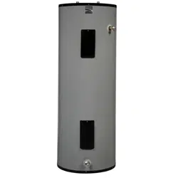
KENHORE
POWER HISERT"8+
ELECTRIC
WATER HEATER
• Safety Instructions
• installation
• Operation
* Care and Maintenance
° Troubleshooting
- Parts List
GAMA certification applies to all residential electric water heaters with
capacities of 20 to 120 Gallons, Input rating of 12 Kw or less at a voltage
no greater than 250 V.
,_WARNING
READ THE GENERAL SAFETY SECTION BEGINNING ON INSIDE COVER
AND THEN THIS ENTIRE MANUAL BEFORE INSTALLING OR OPERAT-
ING THIS WATER HEATER.
Sears, Roebuck and Co., Hoffman Estates, IL 60179 U.S.A.
Safety Precautions
AWARNING
Improper installation, adjustment, alteration, service or main-
tenance can cause death, serious bodily injury, or property
t damage. Refer to this manual for assistance or consult your
localSears Service Center for further information.
_!_WARNING
At the time ofmanufacture this water heater was providedwith a
combination temperature-pressures relief valve certified by a
nationally recognized testing laboratory that maintains periodic
inspectionofproductionof listedequipmentor materials, as meet-
ingthe requirementsfor ReliefValvesand Automatic Gas Shutoff
Devicesfor Hot Water SupplySystems,and the latest editionof
ANSI Z21.22 and the coderequirementsofASHE. If replaced, the
valvemust meet the requirementsoflocalcodes,butnot lessthan
a combination temperature and pressurerelief valve certified as
meeting the requirements for ReliefValvesand Automatic Gas
ShutoffDevicesfor Hot Water SupplySystems,ANSI Z21.22 by a
nationally recognized testing laboratory that maintains periodic
inspectionofproductionof listedequipmentor materials.
The valve must be marked with amaximum set pressurenot
to exceed the marked hydrostatic working pressure of the
water heater (I 50 Ibs./sq.in.)and a discharge capacity not less
than the water heater input rate as shown on the model rating
plate. (Electric heaters - watts divided by 1000 x 3415 equal
BTUiHr. rate.)
Your local jurisdictional authority, while mandating the use of a
temperature-pressure relief valve complying with ANSI Z21.22
andASME, may require a valvemodel differentfrom the one fur-
nishedwith the water heater.
Compliancewith suchlocalrequirements must be satisfiedbythe
installeror end user ofthe water heater with a locallyprescribed
temperature-pressure reliefvalveinstalledin the designatedopen-
ingin the water heater in placeofthe factoryfurnished valve.
Forsafeoperation of the water heater,the relief valvemust not be
removed from it'sdesignatedopeningor plugged.
The temperature-pressure relief valve must be installed directly
intothe fitting ofthe water heater designatedfor the reliefvalve.
Position the valve downward and providetubing so that any dis-
charge will exit only within 6 inches above, or at any distance
belowthe structuralfloor.Be certain that no contactismade with
anyliveelectricalpart. The dischargeopeningmust notbe blocked
or reduced in sizeunder any circumstances.Excessivelength,over
30feet, or useof more than four elbowscan causerestrictionand
reducethe dischargecapacityof the valve.
No valve or other obstructionisto be placed between the relief
valve and the tank. Do not connect tubing directlyto discharge
drain unless a 6" air gap isprovided.To preventbodily injury,haz-
ardto life,or property damage,the relief valvemust be allowedto
dischargewater inquantitiesshouldcircumstancesdemand. If the
dischargepipe isnot connectedto a drain or other suitablemeans,
the water flow may causepropertydamage.
The Discharge Pipe:
• Must not be smaller in size than the outlet pipe size of the
valve, or have any reducing couplingsor other restrictions.
Must not be pluggedor blocked.
Must be of material listedfor hot water distribution.
Must be installed so as to allow complete drainage of both
the temperature-pressure relief valve, and the discharge
pipe.
Must terminate at an adequate drain.
Must not have anyvalve between the relief valveand tank.
_(_WARNING
HAZARD OF ELECTRICAL SHOCK! Before removing
any access panels or servicing the water heater, make
sure the electrical supply to the water heater is turned
"off". Failure to do this could result in death, serious bod-
ily injury, or property damage.
AWARNING
HOTTER WATER CAN SCALD: Water heaters are
intended to produce hot water. Water heated to a tem-
perature which will satisfy space heating, clothes washing,
dish washing, and other sanitizing needs can scald and
permanently injure you upon contact. Some people are
more likely to be permanently injured by hot water than
others. These include the elderly, children, the infirm, or
physlcallylmentally handicapped. If anyone using hot
water in your home fits into one of these groups or if
there is a local code or state law requiring a certain tem-
perature water at the hot water tap, then you must take
special precautions. In addition to using the lowest possi-
ble temperature setting that satisfies your hot water
needs, a means such as a mixing valve, shall be used at
the hot water taps used by these people or at the water
heater. Mixing valves are available at plumbing supply or
hardware stores. Follow manufacturers instructions for
installation of the valves. Before changing the factory set-
ting on the thermostat, read the "Temperature
Regulation" section in this manual
_WARNING
WATER HEATERS EQUIPPED FOR ONE VOLTAGE
ONLY: This water heater isequipped for one type voltage
only. Check the rating plate near the bottom access panel
for the correct voltage. DO NOT use this water heater
with any voltage other than the one shown on the model
rating plate. Failure to use the correct voltage can cause
problems which can result in death, serious bodily injury,
or property damage, if you have any questions or doubts
consult your electric company.
_WARNING
INSULATING JACKETS: When installing an external
water heater insulation jacket on an electric water
heater:
a. DO NOT cover the temperature-pressure relief valve.
b. DO NOT put insulation over the access covers or any
accessareas.
c. DO NOT cover or remove operating instructions, and
safety related warning labels and materials affixed to the
water heater.
_WARNING
Do not use this appliance if any part of it has been under
water. An electrical short or malfunction could occur.
The water heater should be replaced.
_CAUTION
WATER HEATERS EVENTUALLY LEAK: Installation of
the water heater must be accomplished in such a manner
that if the tank or any connections should leak, the flow of
water will not cause damage to the structure. When such
locations cannot be avoided, a suitable drain pan should
be installed under the water heater. Drain pans are avail-
able at your local Sears Store. Such a drain pan must be
_iped to an adequate drain. Under no circumstances is
the manufacturer or Sears to be held liable for any water
damage in connection with this water heater.
f
S !
Fable of Contents
_arety Precautions ............[.i...............................................................................................................................2
Table of Contents ................................................................................................................................................3
Introduction ............................................................................................................................................................... 4
' " 4
Speclficauons .............................................................................................................................................................
Preparing for the New Installation .............................................................................................4
Materials and Basic Tools Needed ...............................................................................................5
Materials Needed ...................................................................................................................................................................... 5
BasiceTools Needed ................................................................................................................................................................. 5
Installation Instructions ........................................................................................................................6-15
Removing the Old Water Heater ............................................................................................................................................... 6
Locating the New Water Heater ................................................................................................................................................ 7
Water Piping ............................................................................................................................................................................. 8
Temperature-Pressure Relief Valve............................................................................................................................................. 9
Fi!ling the Water Heater .......................................................................................................................................................... 10
Converting the Lower Element .................................................. :....................................................................................... 10-!2
Wiring Diagrams .................................................................................................................................................................... 13
Wiring .................................................................................................................................................................................... 14
Installation Checklist .............................................................................................................................................................. 15
Serviceand Adjustment .................................................................................... !5-17
Temperature Regulation.......................................................................................................................................................... 16
Thermostats ............................................................................................................................................................................. 16
Thermostat Settings ................................................................................................................................................................ 16
Thermostat Adjustment .......................................................................................................................................................... 16
Temperature-Pressure Relief ValveOperation .......................................................................................................................... t7
Draining ................................................................................................................................................................................. 17
Trouble Shooting Guide.....................................................................................................................18-23
Thermal Expansion ................................................................................................................................................................. 18
Strange Sounds ....................................................................................................................................................................... 18
Operational Conditions ........................................................ _................................................................................................. 18
Not Enough Hot Water .......................................................................................................................................................... 19
Water is Too Hot .................................................................................................................................................................... 19
Element Cleanin and Replacement .................................................................................................................................... 20-22
Drain ValveWasher Replacement ........................................................................................................................................... 22
Service.................................................................................................................................................................................... 22
Leakage Checkpoints .............................................................................................................................................................. 23
Parts Order List...............................................................................................................................................24_27
Warranty ........................................................................................................................................................................28
Introduction
Thank You for purchasing a Sears water heater.
Propei:ty installed and maintained, it should give you years of
trouble free service, tfyou should decide that you want the new
water heater professionally installed, contact the local Sears
Service Center or any Sears store. They wilt arrange for prompt,
quality installation by Sears authorized contractors.
Abbreviations Found In This Instruction Manual
U.L.-Underwriters Laboratories, 333 Pfingsten Rd., (:...........
Northbrook, IL 60062
National Electrical Code-This publication is available from your :
local government or public library or electric company or by
writing to U.L. above.
A.N.S.I.-American National Standards Institute
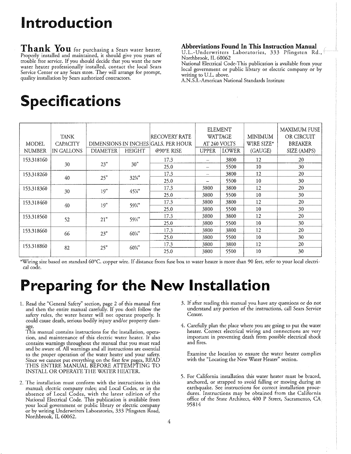
Specifications
MODEL
NUMBER
153.318160
153.318260
153.318360
153.318460
153.318560
I53.318660
153.318860
TANK
CAPACITY
IN GALLONS
30
4O
30
4O
52
66
82
DIMENSIONS IN INCHES
DIAMETER
23"
25"
19"
19"
21"
23"
25"
HEIGHT
30"
32¼"
45_A''
59_A''
59_A"
60¼"
60¼"
RECOVERYFATE
GALS.PER HOUR
ELEMENT
WATTAGE
AT24OVOLTS
@90°ERISE
17.3
25.0
17.3
25.0
17.3
25.0
17.3
25.0
I7.3
25.O
17.3
25.0
17.3
25.O
UPPER
w
3800
3800
3800
3800
3800
3800
3800
3800
3800
3800
LOWER
38OO
55OO
3800
5500
3800
550O
3800
5500
3800
550O
3800
55OO
38OO
55OO
MINIMUM
WIRE SIZE*
(GAUGE)
12
10
12
I0
12
10
12
10
12
10
12
10
12
10
MAXdMUMFUSE
OR CIRCUIT
BREAKER
SIZE (AMPS)
20
30
20
30
20
30
20
30
20
30
20
30
20
30
*Wiring size based on standard 60°C. copper wire. If distance from fuse box to water heater is more than 90 feet, refer to your local electri-
cal code.
Preparing for the New Installation
1. Read the "General Safety" section, page 2 of this manual first
and then the entire manual carefully. If you don't follow the
safety rules, the water hearer will not operate properly. It
could cause death, serious bodily injury and/or property dam-
age.
This manual contains instructions for the installation, opera-
tion, and maintenance of this dectric water heater. It also
contains warnings throughout the manual that you must read
and be aware of.All warnings and all instructions are essential
to the proper operation of the water heater and your safety.
Since we cannot put everything onthe first few pages, READ
THIS ENTIRE MANUAL BEFORE ATTEMPTING TO
INSTALL OR OPERATE THE WATER H_TER.
2. The installation must conform with the instructions in this
manual; electric company rules; and Local Codes, or in the
absence of Local Codes, with the latest edition of the
National Electrical Code. This publication is available from
your local government or public library or electric company
or by writing Underwriters Laboratories, 333 Pfingsten Road,
Northbrook, IL 60062.
3. If after reading this manual you have any questions or do not
understand any portion of the instructions, call Sears Service
Center.
4. Carefully plan the place where you are going to put the water
heater. Correct electrical wiring and connections are very
important in preventing death from possible electrica! shock
and fires.
Examine the location to ensure the water heater complies
with the "Locating the New Water Heater" section.
5. For California installation this water heater must be braced,
anchored, or strapped to avoid falling or moving during an
earthquake. See instructions for correct installation proce-
dures. Instructions may be obtained from the California
office of the State Architect, 400 P Street, Sacramento, C__
95814
Haterials and Basic ools Needed
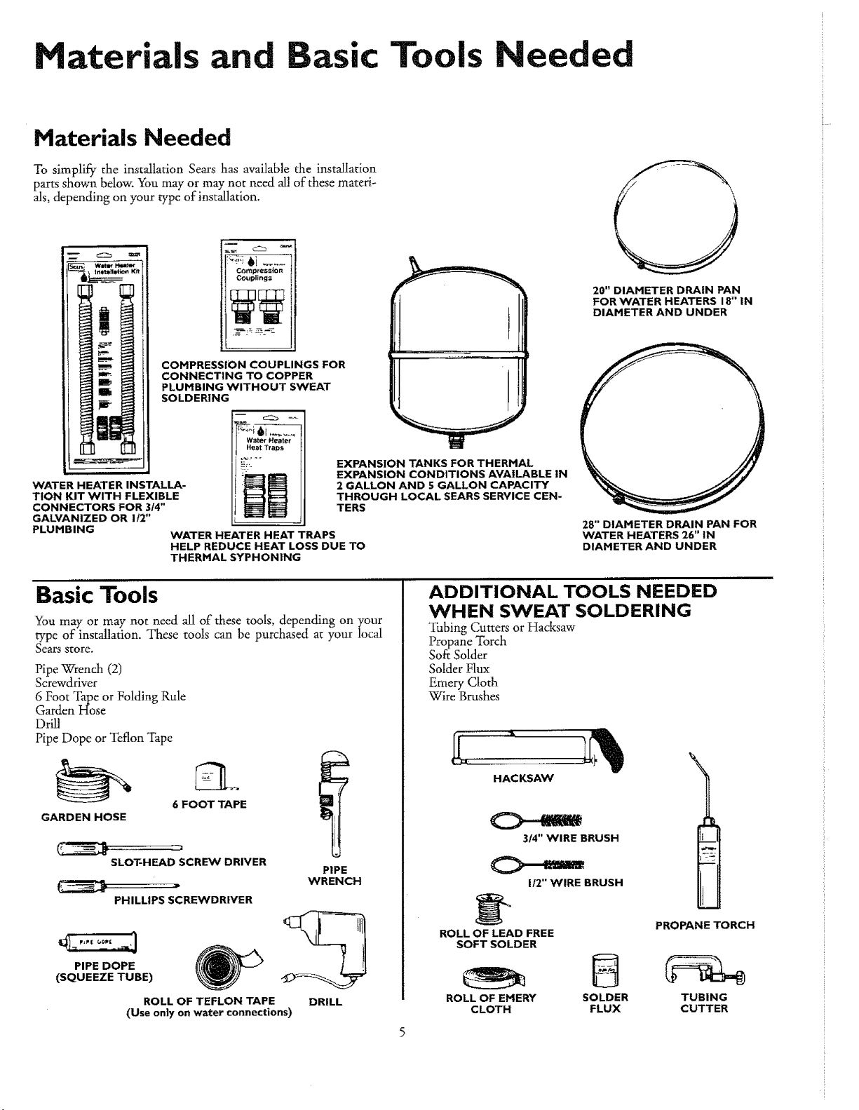
Materials Needed
To simplify the installation Sears has available the installation
parts shown below. You may or may not need all of these materb
als, depending on your type of installation.
WATER HEATER INSTALLA-
TION KIT WITH FLEXIBLE
CONNECTORS FOR 314"
GALVANIZED OR I t2"
Compression
Couplings
COMPRESSION COUPLINGS FOR
CONNECTING TO COPPER
PLUMBING WITHOUT SWEAT
SOLDERING
Water Heater
Heat Tra_s
EXPANSION TANKS FOR THERMAL
EXPANSION CONDITIONS AVAILABLE IN
2 GALLON AND 5 GALLON CAPACITY
THROUGH LOCAL SEARS SERVICE CEN-
TERS
PLUMBING
WATER HEATER HEAT TRAPS
HELP REDUCE HEAT LOSS DUE TO
THERMAL SYPHONING
20" DIAMETER DRAIN PAN
FOR WATER HEATERS 18" IN
DIAMETER AND UNDER
28" DIAMETER DRAIN PAN FOR
WATER HEATERS 26" IN
DIAMETER AND UNDER
Basic Tools
You may or may not need all of"these tools, depending on your
type of installation. These tools can be purchased at your local
Searsstore.
Pipe Wrench (2)
Screwdriver
6 Foot Tape or Folding Rule
Garden Hose
Drill
Pipe Dope or Teflon Tape
6 FOOT TAPE
GARDEN HOSE
SLOT-HEAD SCREW DRIVER
PHILLIPS SCREWDRIVER
PIPE DOPE
(SQUEEZE TUBE)
ROLL OF TEFLON TAPE
PIPE
WRENCH
DRILL
(Use only on Water connections)
ADDITIONAL TOOLS NEEDED
WHEN SWEAT SOLDERING
Tubing Cutters or Hacksaw
Propane Torch
Soft Solder
Solder Flux
Emery Cloth
Wire Brushes
HACKSAW
3/4" WIRE BRUSH
O--,,-
1t2" WIRE BRUSH
ROLL OF LEAD FREE
SOFT SOLDER
B
ROLL OF EMERY SOLDER
CLOTH FLUX
1
PROPANE TORCH
TUBING
CUTTER
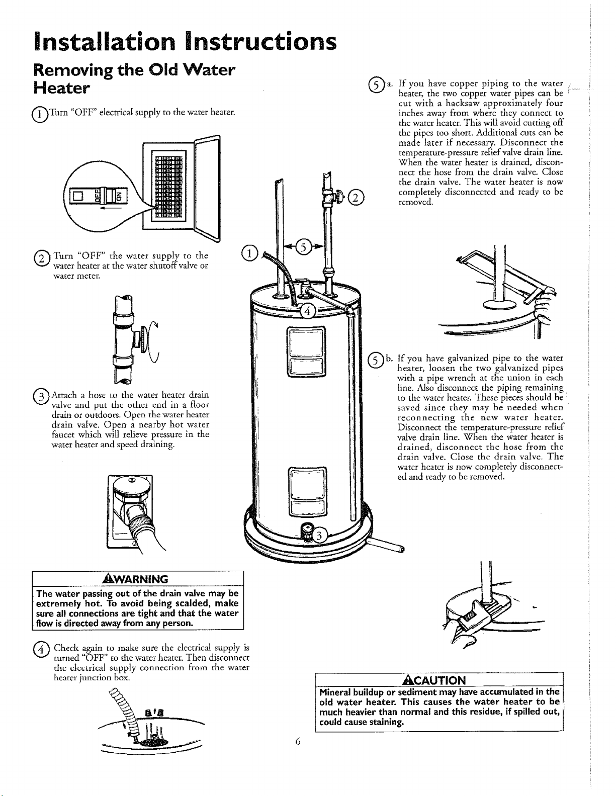
Installation instructions
Removing the Old Water
Heater
Turn "OFF" etectricai supply to the water heater.
-Turn "OFF" the water supply to the
water heater at the water shutoffvalve or
water meter.
O
tf you have copper piping to the water
heater, the two copper water pipes can be ..........
cut with a hacksaw approximately four
inches away from where they connect to
the water heater, This will avoid cutting off
the pipes too short. Additional cuts can be
made later if necessary. Disconnect the
temperature-pressure reliefvalve drain line.
When the water heater is drained, discon-
nect the hose from the drain valve, Close
the drain valve. The water heater is now
completely disconnected and ready to be
removed,
Attach a hose to the water heater drain
valve and put the other end in a floor
drain or outdoors. Open the water heater
drain valve. Open a nearby hot water
faucet which wilt relieve pressure in the
water heater and speed draining.
If you have galvanized pipe to the water
heater, loosen the two galvanized pipes
with a pipe -wrenchat the union in each
line. Also disconnect the piping remaining
to the water heater,These pieces should be{
saved since they may be needed when
reconnecting the new water heater.
Disconnect the temperature-pressure relief
valve drain line. When the water heater is
drained, disconnect the hose from the
drain valve. Close the drain valve. The
water heater is now completely disconnect-
ed and ready to be removed.
,_WARNtNG
[ Thewater passingout of the drain valvemay be
[ extreme|y hot. To avoid being scalded, make
I sureall connectionsare tight andthat the water
I flowisdirected awayfrom any person.
Q Check again to make sure the electrical supply is
turned "OFF" to the water heater. Then disconnect
the electrical supply connection from the water
heater junction box.
I _CAUTION !
Hinerai buildupor sedimentmay haveaccumulatedin the
old water heater. This causes the water heater to be
much heavierthan normal and this residue,if spilledout,i
couldcausestaining.
l
Installation
nstructions (cont'd)
Locating the New Water
Heater
Facts to Consider About the
Location
You should carefully choose an indoor location for the new water
heater, because the placement is a very important consideration
for the safety of the-occupants in the building arid for the most
economical use of the appliance. This water heater is not intend-
ed for outdoor installation.
Whether replacing an old water heater or putting the water
heater in a new location, the following critical points must be
observed.
1. The location selected should be indoors as close to and as cen-
tra]ized with the water piping system as possible. This water
heater, as well as all water heaters, witl eventually leak. Do not
instal! without adequate drainage provisions where water flow
will cause damage.
_CAUTION
WATER HEATERS EVENTUALLY LEAK: Installation of
the water heater must be accomplished in such a manner
that if the tank or any connections should leak, the flow of
water will not cause damage to the structure. When such
locations cannot be avoided, a suitable drain pan should
be installed under the water heater. Drain pans are avail-
able at your local Sears Store. Such a drain pan must be
piped to an adequate drain. Under no circumstances is
the manufacturer or Sears to be held liable for any water
damage in connection with this water heater.
ACAUTION
INSTALLATION IN RESIDENTIAL GARAGES: The
water heater must be located andlor protected so it is not
subject to physical damage by a moving vehicle.
2. The location selection must provide adequate clearances for
servicing and proper operation of the water heater.
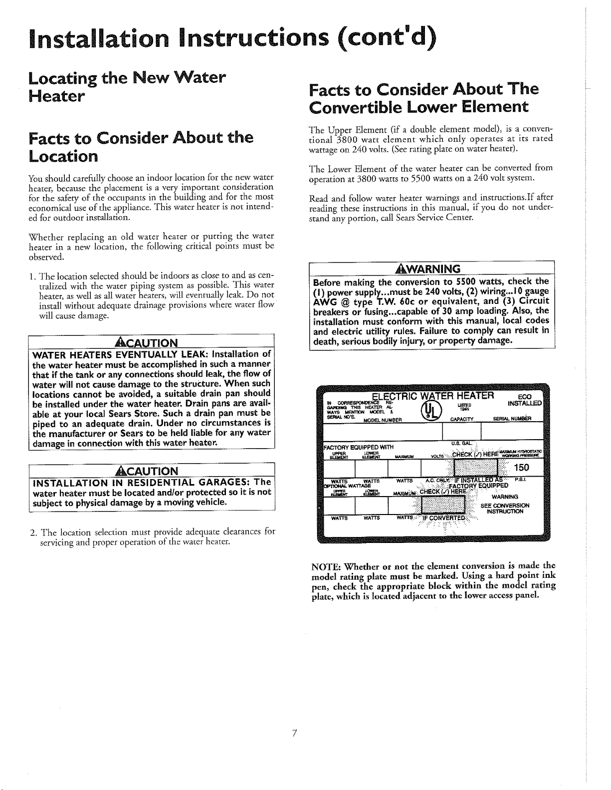
Facts to Consider About The
Convertible Lower Element
The Upper Element (if a double element model), is a conven-
tional 3800 watt element -which only operates at its rated
wattage on 240 volts. (See rating plate on water heater).
The Lower Element of the water heater can be converted from
operation at 3800 watts to 5500 watts on a 240 volt system.
Read and follow water heater warnings and instruc6ons.If a_er
reading these instructions in this manual, if you do not under_
stand any portion, call Sears Service Center.
_I_WARNI NG
Before making the conversion to 5500 watts, check the
(I) power supply...must be 240 volts, (2) wiring...10 gauge
AWG @ type T.W. 60c or equivalent, and (3) Circuit
breakers or fusing...capable of 30 amp loading. Also, the
installation must conform with this manual, local codes
and electric utility rules. Failure to comply can result in
death, serious bodily injury, or property damage.
NOTE: Whether or not the element conversion is made the
model rating plate must be marked. Using a hardpoint ink
pen, check the appropriate block within the model rating
plate, which is located adjacent to the lower access panel.

installation
nstructions (cont'd)
Water Piping
_WARNtNG
HOTTER WATER CAN SCALD: Water heaters are
intended to produce hot water. Water heated to a tem-
perature which will satisfy space heating, clothes washing,
dish washing, and other sanitizing needs can scald and
permanently injure you upon contact. Some people are
more likely to be permanently injured by hot water than
others. These include the elderly, children, the infirm, or
physicallylmentally handicapped. If anyone using hot
water in your home fits into one of these groups or if
there isa local code or state law requiring a certain tem-
perature water at the hot water tap, then you must take
special precautions. In addition to using the lowest possi-
ble temperature setting that satisfies your hot water
needs, a means such as a mixing valve, shall be used at
the hot water taps used by these people or at the water
heater. Hixing valves are available at plumbing supply or
hardware stores. Follow manufacturers instructions for
installation of the valves. Before changing the factory set-
ting on the thermostat, read the "Temperature
Regulation" section in this manual.
The illustration shows the attachment of the water i ing to the
PP
water heater. The water heater is equipped with % inch water
connections.
If a water heater is installed in a closed water supply system; such
as one having a back-flow preventer, check valve, water meter
with a check valve, etc. in the cold water supply; means shall be
provided to control thermal expansion. Contact the local utility
or local Sears Service Center on how to control this situation.
NOTE: If using copper tubing, solder tubing to an adapter
before attaching the adaptor to the cold water inlet connec-
tion. Do not solder the cold water supply llne directly to the
cold water inlet. It w_ harm the dip tube and damage the
tank.
1. Look at the top cover of the water heater. The water outlet is
marked hot. Put two or three turns of teflon tape around the
threaded end of the threaded-to-sweat coupling and around
both ends of the "%"threaded nipple. Using flexible connec-
tors, connect the hot water pipe to the hot water outlet of the
water heater.
2. Look at the top cover of the water heater. The cold water inlet
is marked cold. Put two or three turns of teflon tape around
the threaded end of the threaded-to-sweat coupling and
around both ends of the %" threaded nipple. Using flexible
connectors, connect the cold water pipe to the cold water inlet
of the water heater.
NOTE: Yourwater heater is super insulated to minimize heat
loss from the tank. Further reduction in heat toss can be
accomplished by insulating the hot water lines from the
water heater.
Installation completed using Sears
Installation Kit
[ .......
HOT OUTLET
T OUSEl
THREADED TO
SWEAT COUPLIN
3/4" THREADED-_
NIPPLE
FLEXIBLE
WATER
CONNECTORS
®
SHUT-OFF
VALVE
COLD INLET
/ WATER LINE
THREADED TO
SWEAT COUPLING
314" THREADED
NIPPLE
TEMPERATURE-
PRESSURE
RELIEF VALVE
DISCHARGE PIPE
(Do not cap or plug)
6" AIR GAP
FLOOR DRAIN
Installation
nstructions (cont'd)
Temperature-Pressure
Relief Valve
_kWARNING
At the time of manufacture this water heater was provid-
ed with a combination temperature-pressures relief valve
certified by a nationally recognized testing laboratory that
maintains periodic inspection of production of listed equip-
ment or materials, as meeting the requirements for Relief
Valves and Automatic Gas Shutoff Devices for Hot Water
Supply Systems, and the latest edition of ANSI Z21.22 and
the code requirements of ASME. If replaced, the valve
must meet the requirements of local codes, but not less
than a combination temperature and pressure relief valve
certified as meeting the requirements for Relief Valves and
Automatic Gas Shutoff Devices for Hot Water Supply
Systems, ANSI Z21.22 by a nationally recognized testing
laboratory that maintains periodic inspection of produc-
tion of listed equipment or materials.
The valve must be marked with a maximum set pressure
not to exceed the marked hydrostatic working pressure of
the water heater (i 50 lbs.lsq, in.) and a discharge capacity
not lessthan the water heater input rate as shown on the
model rating plate. (Electric heaters - watts divided by
1000x 3415 equal BTU/Hr. rate.)
Your local jurisdictional authority, while mandating the use
of a temperature-pressure relief valve complying with
ANS! Z21.22 and ASME, may require a valve model differ-
ent from the one furnished with the water heater.
Compliance with such local requirements must be satisfied
by the installer or end user of the water heater with a
locally prescribed temperature-pressure relief valve
installed in the designated opening in the water heater in
place ofthe factory furnished valve.
For safe operation of the water heater, the relief valve
must not be removed from it's designated opening or
plugged.
The temperature.pressure relief valve must be installed
directly into the fitting of the water heater designated for
the relief valve. Position the valve downward and provide
tubing so that any discharge will exit only within 6 inches
above, or at any distance below the structural floor. Be
certain that no contact is made with any live electrical
_art. The discharge opening must not be blocked or
reduced in size under any circumstances. Excessivelength,
over 30 feet, or use of more than four elbows can cause
restriction and reduce the discharge capacity of the valve.
No valve or other obstruction isto be placed between the
relief valve and the tank. Do not connect tubing directly to
discharge drain unlessa 6" air gap is provided. To prevent
bodily injury, hazard to llfe, or property damage, the relief
valve must be allowed to discharge water in quantities
should circumstances demand. If the discharge pipe is not
connected to a drain or other suitable means, the water
flow may cause property damage.
The Discharge Pipe:
-- Must not be smaller in size than the outlet pipe size of
the valve, or have any reducing couplings or other
restriction.
-- Must not be plugged or blocked.
Must be of material listed for hot water distribution.
Must be installed so asto allow complete drainage of
both the temperature-pressure relief valve, and the dis-
charge pipe.
-- Must terminate at an adequate drain.
Must not have any valve between the relief valve and
tank.
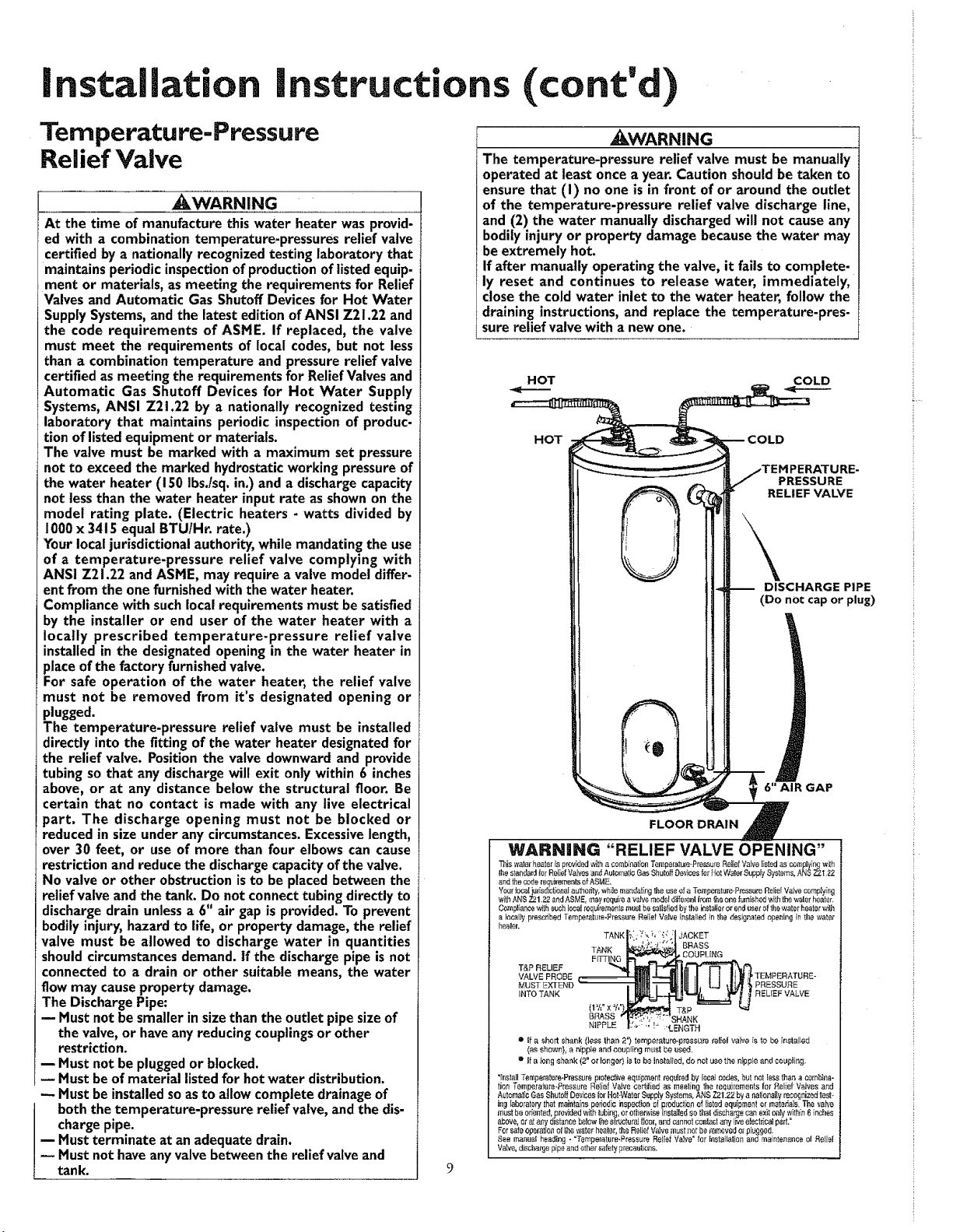
_I_WARNING
The temperature-pressure relief valve must be manually
operated at least once a year. Caution should be taken to
ensure that (I) no one is in front of or around the outlet
of the temperature-pressure relief valve discharge line,
and (2) the water manually discharged will not cause any
bodily injury or property damage because the water may
be extremely hot.
If after manuaUy operating the valve, it fails to complete-
ly reset and continues to release water, immediately,
close the cold water inlet to the water heater, follow the
draining instructions, and replace the temperature.pres-
sure relief valve with a new one.
HOT COLD
HOT COLD
PRESSURE
RELIEF VALVE
DISCHARGE PIPE
(Do not cap or plug)
6"AIR GAP
FLOOR DRAIN
WARNING "RELIEF VALVE OPENING"
Taiswaterheaterisprevid_ w_ha earabinalionTempara_J=e-Pres_uraReliefValvelisledas_m_lying with
Ihestandardfor Ral;efValvasa_ AutomaticGasSh_tdfDevicesfarHotWaistSupplySystems,ANSZ2.1.22
and the coda requiremenls of ASME.
Your toca! j_dsdlcheaat author,i, while masdating the use of a Tempei'atul'e-P_'essare Relief VaJve complying
wJLhANSZ21.22andASME, mayrequirea valvemeuefd_ereallrotn_,eonefamished_ithth_waterheater.
Compliancewit_suohlocalrequirementsm_l be satisfiedbythe ieslaIlatorecduserafthe water_eatarv_
a lasalJy prescribed Temperalure-Frsss,_re Relief Valve inalalled in the designated opening in the water"
heater.
TANKI;"i: :' _:;' _?,:1JACKET
FiR'_ COUPLINGl{'_ f'_
T&P RELIEF
_1111 a-.-_UlIII!_11I i111;_'TEMPERATURE-VALVE PROSE
MUSTEXTEND_tl!lll ,-_UtlIIIIII, LJ ti_t'',_PRESSURE
INTOTANK L_t_j_______________, t _ RELIEFVALVE
NIPPLE _:.,,.; !-, "_EitGTH
=' tf a short shank (less than 2'} temperature.pressure relief valve is to be [natalJed
(asshown}, a nipple andcoupling must beused.
** if a ices shank (2"ot longer) Lstobe installed,de net use thenipple andcou#ting.
"install Temperature-Pressure Fotective equipment roqekad by leeaJ codes, but not lass theP, a combi_qa-
tion Temperathre-Pressare Relief Valve certi|ied as meeting the Iequiremeats far Relief V_lvas and
AutomaticGasShuto_Devbesk,r Hot-WaterSupplySystems,AN-e,Z21.22bya nationallyreeafnizedtest-
ir,glaboratorythatmaintainspefiodioinspectior,c{pred'..=c_iasof Iistedequipmentormaterials.Thevalve
must be oriented, p[evMed w_ tubing, or ether,vise installed so that discharge can exit ea_ within 6 inches
above,orat&qydistanceheIow_e siructuraJgear,andcannotcontactanyliaeafect_'calpad."
Forsafeoperationof_e waferhealer,theReliefVaJvemustnet beremovedel pl'agged.
See manual heading - "Tam,ee/atere-Pressure Relief Valve ° tar installation arid raaintenanee el Relief
VaIve, discha_'ge pipe and ethe_"safely _reeaut_on&

Installation Instructions (cont'd)
Filling the Water Heater
To fill the water heater with water:
1. Close the water heater drain valve by turning the handle to
the right (clockwise). The drain valveis on the lower front of
the water heater.
2. Open the cold water supply valve to the water heater.
NOTE: The cold water supply valve must be left open
when the water heater is in use.
3. To insure complete filling of the tank, allow air to exit by
opening the nearest hot water faucet. Allow water to run
until a constant flow is obtained. This will let air out of the
water heater and the piping.
CAUTION
Never use this water heater unless it is completely full of
water. To prevent damage to the tank and heating ele-
ment, the tank must be filled with water. Water must
flow from the hot water faucet before turning "ON"
power.
4. Check all new water piping for leaks. Repair as needed.
Converting the Lower
Element
These instructions only cover the conversion of the convertible
element, read this entire manual before attempting to install or
operate the water heater. The water heater is factory set to oper-
ate at 3800 watts. The lower element can be converted to oper-
ate at 5500 watts. Refer to the "Facts to Consider About the
Convertible Lower Hement" section.
The Upper Hement, (if a double element modal) is a conven-
tional 3800 watt element which only operates at its rated
wattage on 240 volts. (See rating plate on water heater).
The Lower Element of the water heater can be converted from
operation at 3800 watts to 5500 watts on a 240 volt system.
tf after reading these instructions and this manual, if you do not
understand any portion, cal! Sears Service Center.
_i WARNING
Before making the conversion to 5500 watts, check the
(1) power supply...must be 240 volts, (2) wiring... 10 gauge
AWG @ type T.W. 60c or equivalent, and (3) Circuit
breakers or fusing..capable of 30 amp loading. Also, the
installation must conform with this Manual, local codes
and electric utility rules. FAILURE TO COMPLY CAN
RESULT IN DEATH, SERIOUS BODILY INJURY OR
PROPERTY DAMAGE.
NOTE= Whether or not the element conversion is made the
model rating plate must be marked, Using a hard point ink
pen, check the appropriate Mock within the model rating
plate, which is located adjacent to the lower access panel.
Necessary element conversion parts are located in a small bag
contained within the large plastic manual envelope attached to
the side of the water heater.
CONVERSION PARTS
SCREW
BUSS BAR
10
1.
Before beginning the conversion turn "OFF" electric power
supply to the water heater.
_KWARNING t
HAZARD OF ELECTRICAL SHOCK! Before removing
any access panels or servicing the water heater, make
sure the electrical supply to the water heater is turned
"OFF". FAILURE TO DO THIS COULD RESULT IN
DEATH, SERIOUS BODILY INJURY, OR PROPERTY
DAMAGE.
Installation Instructions (cont'd)
Converting the Lower
Element (cont'd)
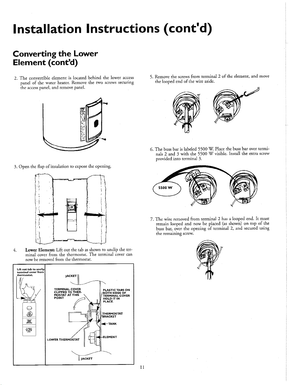
2. The convertible element is located behind the lower access
panel of the water heater. Remove the two screws securing
the access panel, and remove panel.
3. Open the flap of insulation to expose the opening.
.
iL ,L if_ i ._,-
i;2 _t k___J_ i,
Lower Element: Lift out the tab as shown to undip the ter-
minal cover from the thermostat. The terminal cover can
now be removed from the thermostat.
Lift out tab to uncli_
terminal covsr from
thermostat_
JACKET
TERMINAL COVER PLASTIC TABS ON
CLIPPED TO THER- BOTH SIDES OF
MOSTAT AT THIS RHINAL COVER
PO|NT HOLD IT IN
PLACE.
LOWER THERMOSTAT
5. Remove the screws from terminal 2 of the element, and move
the looped end of the wire aside.
6. The buss bar is labeled 5500 W. Place the buss bar over termi-
nals 2 and 3 with the 5500 W visible. Install the extra screw
provided into terminaJ 3.
7. The wire removed from terminal 2 has a looped end. It must
remain looped and now be placed (as shown) on top of the
buss bar, over the opening of terminal 2, and secured using
the remaining screw.
11

installation instructions (cont'd)
Converting the Lower
Elernent (cont'd)
8. Tighten terminals 2 and 3 to ensure proper electrical connec-
tion.
11. Replace the access panel.
_WARNING
Failure to tighten terminal screws can cause a fire which
can result in DEATH, SERIOUS BODILY INJURY, OR
PROPERTY DAMAGE.
9. Replace terminal cover on thermostat and fold insulation back
over the element making sure that the locking tabs on the ter-
minal cover are in place.
P
AWARNING
Hake sure the thermostat is flush against the tank, the
terminal cover is in place, and the insulation is replaced.
Failure to do so can result in DEATH, SERIOUS BODILY
INJURY, OR PROPERTY DAMAGE.
12. Complete wiring to the water heater, or if completed, turn
"ON" electric power to the water heater after filling the
tank with water.
10. Fold the insulation back in place so that it completely covers
the thermostat and element.
!
A CAUTION
Never use this water heater unless it is completely full of i
water. To prevent damage to the tank and heating ele- i
ment, the tank must be filled with water. Water must t
flow from the hot water faucet before turning "ON" t
power. .._j
12

Installation Instructions (cont'd)
Wiring Diagrams
STANDARD WIRING FOR
2 WIRE LEAD WATER HEATERS
240 VOLT SINGLE ELEMENT
°
==
FOR 3800 WATTS
TO ELECTRIC
POWER SUPPLY
LOWER
HEATING ELEMENT
TO ELECTRIC
POWER SUPPLY
Ill
i_-_._ i
FOR 5500 WATTS _/_&-4_4L__
FOR 3800 WATTS "___H EATILOWELERMEN T
WIRING FOR 3 WIRE LEAD WATER HEATERS
NON-SIMULTANEOUS OPERATION
240 VOLT DOUBLE ELEMENT
UPPER E.C.O. &
THERMOSTAT
LOWER
T'STAT
FOR 3800 WATTS
m
*NOTE: Some Lower Hi-Temp Limit
Switches may have 4 terminals. Use only
the 2 terminals on left.
LOWER
HEATING ELEMENT
13
_=_ THREE TYPES OF FIELD
CONNECTIONS YOU MAY
HAVE
1. TIME CLOCK SWITCH
OPERATES BOTTOM ELEMENT ONLY
TO ELECTRIC _ n _ TO TIME
PowersuPPLY L1_L2 _2 CLOCKSWITCH
IA ,__ A IjUNCTION
BOX
YELLOW[ "=_'BI'U ElB_ACK
ii i uinllllllllu
2. "OFF PEAK_'METER
OPERATES BOTTOM ELEMENT ONLY
TO ELECTRIC ____ L1 L2-PTO "OFF PEAK"
PowerSUPPLYLt _L.tt MEter
f Jl- !
YELLOWI =.IEBLUEIBLACK
111 ii
3. FOR TWO WIRE CONNECTION
TO ELECTRIC
POWER SUPPLY L1 L2
/ I t \ ! BOX
vELLowl%LbhB CK
II I[ [lllll[ll I1[

Installation Instructions (cont'd)
VViring
_CAUTION i
Never use this water heater unless it is completely full of I
water. To prevent damage to the tank and heating ele- I
ment, the tank must be filled with water. Water must
flow from the hot water faucet before turning on power.
You must provide all wiring of the proper size outside of the
water beater. You must obey local codes and electric company
requirements when you instal! this wiring.
C. Flexible metal conduit or flexible metallic tubing shall be
permitted for grounding if all the following conditions are
met."
1. The length in any ground return path does not exceed
6 feet.
2. The circuit conductors contained therein are protected
by overcurrent devices rated at 20 amperes or less.
3. The conduit or tubing is terminated in fittings
approved for grounding.
For comnpllete grounding details and all allowable exceptions,
refer to the latest edition of the National Electrical Code.
If you are not fan-filiar with electric codes and practices, or if you 4.
have any doubt, even the slightest doubt, in your ability to con-
nect the wiring to this water heater, obtain the service of a com-
petent electrician. Contact your Sears salesperson to arrange for a 5.
professional electrician.
_WARNING
WATER HEATERS EQUIPPED FOR ONE VOLTAGE
ONLY: This water heater is equipped for one type voltage
only. Check the rating plate near the bottom access
panel for the correct voltage. DO NOT use this water
heater with any voltage other than the one shown on the
model rating plate. Failure to use the correct voltage can
cause problems which can result in DEATH, SERIOUS
BODILY INJURY, OR PROPERTY DAMAGE. If you have
any questions or doubts consult your electric company.
_CAUTION
If wiring from your fuse box or circuit breaker box was
aluminum for your old water heater, replace it with cop-
per wire. If you wish to reuse the existing aluminum wire,
have the connection at the water heater made by a com-
petent electrician. Contact your Sears salesperson to
arrange for a professional electrician.
1. Provide a way to easilyshut off the electric power when work-
ing on the water heater. This could be with a circuit breaker
or fuse block in the entrance box or a separate disconnect
switch.
2. Install and connect a circuit directly from the main fuse or cir-
cuit breaker box. This circuit must be the right size and have
its own fuse or circuit breaker. Refer to the chart in the
"Specifications" section for the correct size wire and fuse or
circuit breaker.
3. If metal conduit is usedfor the grounding conductor:
A. The grounding electrode conductor shall be of copper,
aluminum, or copperclad aluminum. The material shall
be of one continuous length without a splice or joint.
B. Rigid metal conduit, intermediate metal conduit, or elec-
trical metallic tubing may be used for the grounding
means if conduit or tubing is terminated in fittings
approved for grounding.
A standard _A"conduit opening has been made in the water
heater junction box for the conduit connection.
Wiring Diagrams (See Wiring Diagrams Section) have been
supplied showing the two most common types of connections
between the water heater and the power supply. You can easi-
ly see which type connection you have by removing the junc-
tion box cover on top of the water heater.
A. Two Wire Connection Diagrams: is the most common
requiring you to simply connect red to red, black to black,
and the ground wire to the green ground screw in the junc-
tion box of the water heater.
B. Three W'tre Connection Diagram: is used when you are
connecting the water heater to power a supply that has a
"Time Clock" or "Off Peak" Meter. To make these connec-
tions refer to block ! or 2 in this wiring diagram for the type
of system you have.
NOTE: If you have purchased a three wire connection water
heater but you are not on a "Time Clock" or "Off Peak"
meter and have a standard two wire connection power supply,
simply follow the connection diagram in block 3. of the
Three Wire Connection Diagram.
.
.
Use wire nuts and connect the power supply wiring to the
wires inside the water heater's junction.
The water heater must be electrically "grounded" by the
installer. A green ground screw has been provided on the
water heater's junction box. Connect ground wire to this
location.
8. Replace the wiringjunction cover using the screw provided.
14
"GREEN
GROUND
SCREW
Installation Instructions (cont'd)
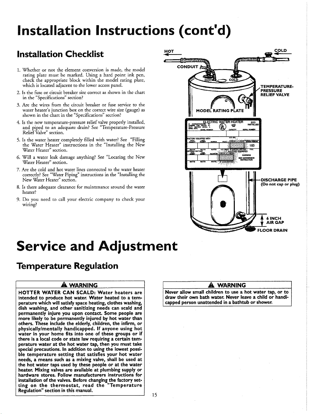
Installation Checklist
1. Whether or not the element conversion is made, the model
rating plate must be marked. Using a hard point ink pen,
check the appropriate block within the model rating plate,
which is located adjacent to the lower access panel.
2. Is the fuse or circuit breaker size correct as shown in the chart
in the "Specifications" section?
3. Are the wires from the circuit breaker or fuse service to the
water heater's, l'uncti°n, box,,on the. correct., wire. size (gauge) as
shown m the chart in the Specifications section?
4. Is the new temperature-pressure relief valve properly installed,
and piped to an adequate drain? See "Temperature-Pressure
Relief Valve" section.
5. Is the water heater completely filled with water? See "Filling
the Water Heater" instructions in the "Installing the New
Water Heater" section.
6. Will a water leak damage anything? See "Locating the New
Water Heater" section.
7. Are the cold and hot water lines connected to the water heater
correctly? See "Water Piping" instructions in the "Installing the
New Water Heater" section.
8. Is there adequate clearance for maintenance around the water
heater?
9. Do you need to call your electric company to check your
wiring?
HOT
COLD
CONDUIT
TEMPERATURE-
MODEL RATING PLATE
RELIEF VALVE
PIPE
(Do not cap or plug)
Service and Adjustment
Temperature Regulation
6 INCH
AIR GAP
FLOOR DRAIN
WARNING
HOTTER WATER CAN SCALD: Water heaters are
intended to produce hot water, Water heated to a tem-
perature which will satisfy space heating, clothes washing,
dish washing, and other sanitizing needs can scald and
permanently injure you upon contact. Some people are
more likely to be permanently injured by hot water than
others. These include the elderly, children, the infirm, or
physically/mentally handicapped, if anyone using hot
water in your home fits into one of these groups or if
there isa local code or state law requiring a certain tem-
perature water at the hot water tap, then you must take
special precautions. In addition to using the lowest possi-
ble temperature setting that satisfies your hot water
needs, a means such as a mixing valve, shall be used at
the hot water taps used by these people or at the water
heater. Mixing valves are available at plumbing supply or
hardware stores. Follow manufacturers instructions for
installation of the valves. Before changing the factory set-
ting on the thermostat, read the "Temperature
Regulation" section in this manual.
_, WARNING
Never allow small children to use a hot water tap, or to
draw their own bath water. Never leave a child or handi-
capped person unattended in a bathtub or shower.
15

Service and Adjustment (cont'd)
Thermostats
The thermostat(s) of this water heater have been factory set at
their !owest position which approximates 120°F (Hot) to reduce
the risk of scald injury.
The upper thermostat (dual element models only) is not
adjustable. Its temperature setting is fixed to approximate 120°F
(Hot).
(DUAL ELEMENT MODELS ONLY)
UPPER THERMOSTAT NOT ADJUSTABLE
BEHIND UPPER ACCESS PANEL
The lower thermostat is factory set at its lowest position which
approximates 120°F (Hot) and is adjustable if a different water
temperature is desired. Read all warnings in this manual and on
the water heater before proceeding.
111
Temperature Settings
HOT-Is a thermostat setting of approximately 120°F,
which will supply hot water at the most economi-
ca] temperatures.
A-Is a thermostat setting of approximately 130°E
B-Is a thermostat setting of approximately 140°F.
This is the lowest setting for supply of hot water
to dishwashers.
C-Is a thermostat setting of approximately 150°E
VERY HOT-Is a thermostat settingof approximately 160°E It is
recommended that the dial be set lower whenever
possible.
Thermostat Adjustment
The upper and lower thermostats have been factory set at hot
(approximately 120°F) to reduce the risk of scald injury.
The upper thermostat (dual element models only) is not
adjustable. The lower thermostat is adjustable ifa different water
temperature is desired. Read all warnings in the "Temperature-
Regulation" section before proceeding.
The adjustment dial can be turned clockwise (__.J) to
increase the temperature setting or counter clockwise
_.._) to decrease the temperature setting.
LOWER THERMOSTATADJUSTABLE
THROUGH LOWER ACCESSPANEL
16

Service Adjustment (cont'd)
Temperature-Pressure Relief
Valve Operation
The temperature-pressure relief valve must be manually operated
at least once a year.
_Nx EHPERATURE'PRESSURE
RELIEF VALVE
DISCHARGE PIPE
Draining
The water heater should be drained if being shut down during
freezing temperatures, Also periodic draining and cleaning of
sediment from the tank may be necessary.
1. Before beginning turn "OFF" the electric power supply to the
water heater,
_WARNING
HAZARD OF ELECTRICAL SHOCK! Before removing
any access panels or servicing the water heater, make
sure the electrical supply to the water heater is turned
"off". Failure to do this could result in DEATH, SERIOUS
BODILY INJURY, OR PROPERTY DAHAGE.
_WARNING
The temperature-pressure relief valve must be manually
operated at least once a year. Caution should be taken to
ensure that (I) no one is in front of or around the outlet
of the temperature-pressure relief valve discharge line,
and (2) the water manually discharged will not cause any
property damage or bodily injury. The water may be
extremely hot.
If after manually operating the valve, it fails to complete-
ly reset and continues to release water, immediately
close the cold water inlet to the water heater, follow the
draining instructions, and replace the temperature-pres-
sure relief valve with a new one.
Failure to install and maintain a new properly listed tempera-
ture-pressure relief valve wilt release the manufacturer from any
claim which might result from excessivetemperature or pressure.
AWARNING
If the temperature.pressure relief valve on the appliance
weeps or discharges periodically, this may be clueto ther.
mal expansion. Your water heater may have a check valve
installed in the water line or a water meter with a check
valve. Consult your local Sears Service Center for further
information. Do not plug the temperature-pressure relief
valve.
2. CLOSE the cold water inlet valve to the water heater.
3. OPEN a nearby hot water faucet and leave open to allow for
draining.
4. Connect a hose to the drain valve and terminate to an ade-
quate drain or outdoors.
5. OPEN the water heater drain valve to allow for tank draining.
NOTE: If the water heater is going to be shut down and
drained for an extended period, the drain valve should be
left open with hose connected allowing water to terminate
to an adequate drain.
6. Close the drain valve,
7. Follow "Filling the Water Heater" instructions in the
"Installing the New Water Heater" section.
8. Turn "ON" power to the water heater.
I ACAUTION
Never use this water heater uniess it is completely full
water. To prevent damage to the tank and heating ele-
ment, the tank must be tiffed with water. Water must
/flow from the hot water faucet before turning 0
/power.
17
Troubleshooting Guide
Start Up Conditions
THERMAL EXPANSION
Water supply systems may, because of high line pressure, fre-
quent cut-offs, the effects of water hammer and others, have
installed devices such as pressure reducing valves, check valves,
back flow preventers, etc...to control these tTpes of problems.
When these devices are not equipped with an internal by-pass,
and no other measures are taken, the devices cause the water sys-
tem to be dosed. As water is heated, it expands (thermal expan-
sion) and closed systems do not allow for the expansion of heated
water.
The water within the water heater tank expands as it is heated
and increases the pressure of the water system. If the relieving
oint of the water heater's tem erature- ressure relief valve is
P P P
reached, the valve will relieve the excess pressure. The tempera-
ture-pressure relief valve is not intended for the constant
relief of thermal expansion. This is an unacceptable condition
and must be corrected.
It is recommended that any devices installed which could create a
closed system, have a by-pass and/or the system have an expan-
sion tank to relieve the pressure built by thermal expansion in
the water system. Expansion tanks are available for ordering
through the Sears Service Center. Contact the local water suppli-
er and/or Seas Service Center for assistance in controlling these
situations.
STRANGE SOUNDS
Possible noises due to expansion and contraction of some metal
arts during periods of heat-up and cool-down do not represent
armful or dangerous conditions.
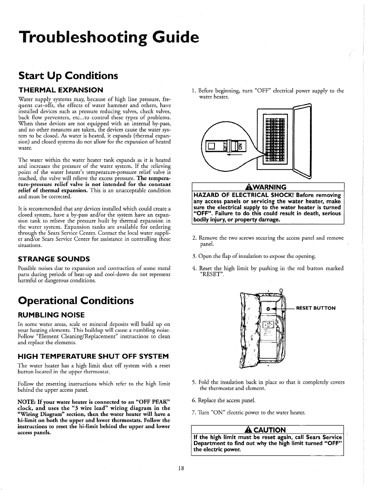
1. Before beginning, turn "OFF" dectrical power supply to the
water heater.
2. Remove the two screws securing the access pand and remove
pand.
3. Open the flap of insulation to expose the opening.
4. Reset tile high limit by pushing in the red button marked
"RESET".
Operational Conditions
RUMBLING NOISE
In some water areas, scale or mineral deposits will build up on
your heating elements. This buildup will cause a rumbling noise.
Follow "Element Cleaning/Replacement" instructions to clean
and replace the elements.
HIGH TEMPERATURE SHUT OFF SYSTEM
The water heater has a high limit shut off system with a reset
button located in the upper thermostat.
Follow the resetting instructions which refer to the high limit
behind the upper access panel.
NOTE: If your water heater is connected to an "OFF PEAK"
clock, and uses the "3 wire lead" wiring diagram in the
"Wiring Diagram" section, then the water heater will have a
hi-limit on both the upper and lower thermostats. Follow the
instructions to reset the hi-limlt behind the upper and lower
access panels.
--RESETBUTTON
5. Fold the insulation back in place so that it completely covers
the thermostat and element.
6. Replace the access panel.
7. Turn "ON" electric power to the water heater.
A CAUTION
t lf the high limit must be reset again, call Sears Service
Department to find out why the high limit turned "OFF"
the electric power,
18
troubleshooting Guide (cont'd)
NOT ENOUGH OR NO HOT WATER
1.
tn a new installation, the water heater may not be properly
connected. Make sure the cold water supply valve is open.
Review and check piping installation. Make sure that the
cold water line is connected to the cold water inlet to the
water heater and the hot water line to the hot water outlet
on the water heater.
2. Make sure the electrical supply to your water heater is
"ON".
3. Check for loose or blown fuses in your water heater circuit.
Circuit breakers weaken with age and may not handle their
rated load and should be replaced.
4. Make certain the disconnect switch, if used, is in the "ON"
position.
5. Check to see the electric service to your house has not been
interrupted. If this is the case, contact the electric company.
6. Are the thermostats set to the desired temperature? See
"Temperature Regulation" section.
7. If you had experienced very hot water and now no hot water,
the problem may be due to the high temperature shut off
system. See High Temperature Shut Off System in t e
"For Your Information" section.
8.
,
During very cold weather, the incoming water will also be
colder and it will require a longer time to become heated.
The hot water usage may exceed the capacity of the water
heater. If so, wait ror water heater to recover after abnormal
demand. Mso examine pipes and faucets for possible water
leaks.
10. If you can not determine the problem, then call the Sears
Service Department.
WATER IS TOO HOT
Adjust the thermostat to a lower setting. See the "Temperature
Regulation" section.
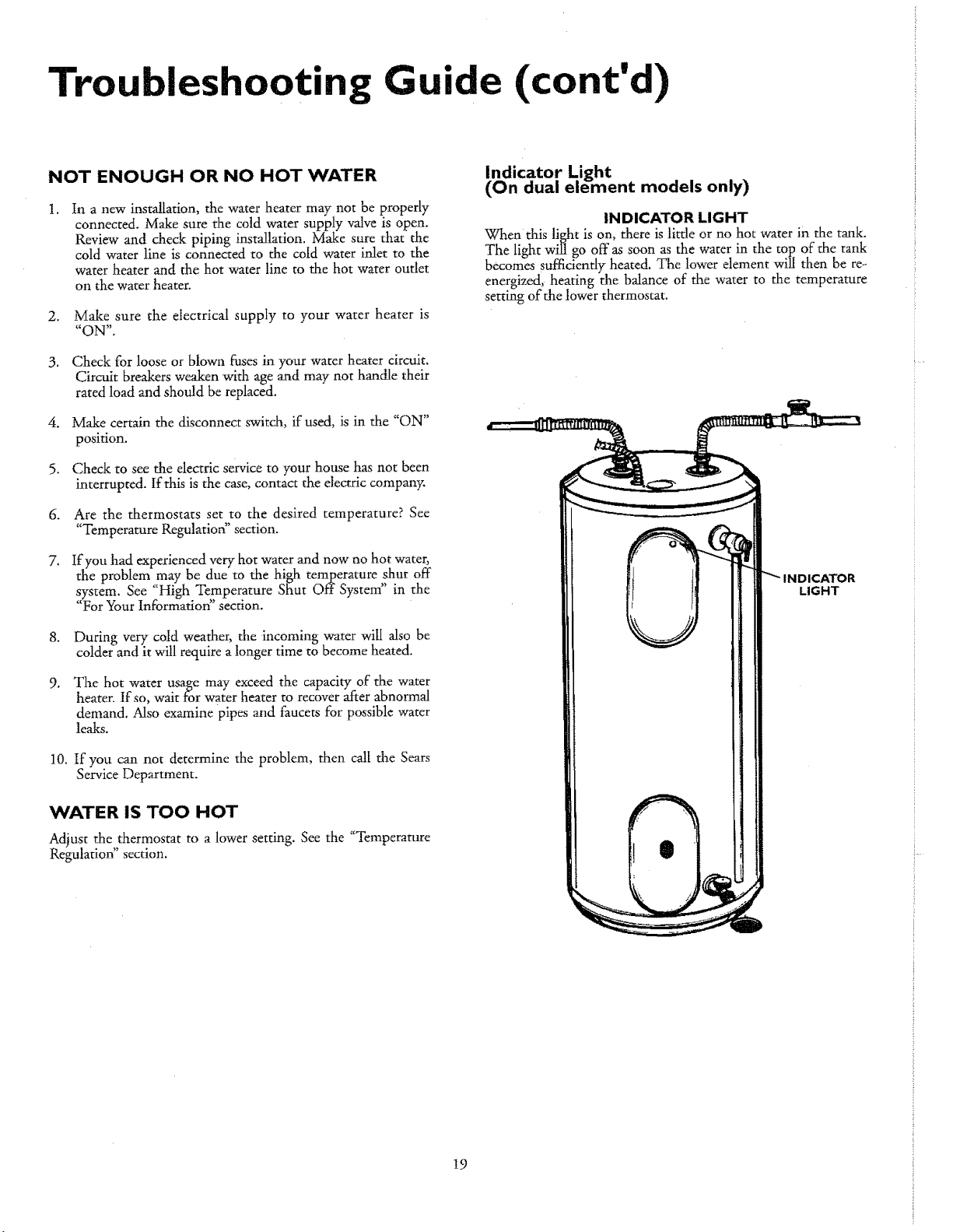
Indicator Light
(On dual element models only)
INDICATOR LIGHT
When this light is on, there is little or no hot water in the tank.
The light wingo off as soon as the water in the top of the tank
becomes sufficiently heated. The lower element will then be re-
energized, heating the balance of the water to the temperature
setting of the lower thermostat.
INDICATOR
LIGHT
{
19
Trou
ooting uide (cont'd)
Element Cleaning/
Replacement
NOTE: These instructions are written for element cleaning
and dement replacement for the lower element. If it is neces-
sary to dean or replace the upper element, then repeat these
instructions.
To remove the element from your tank in order to clean or
replace it:
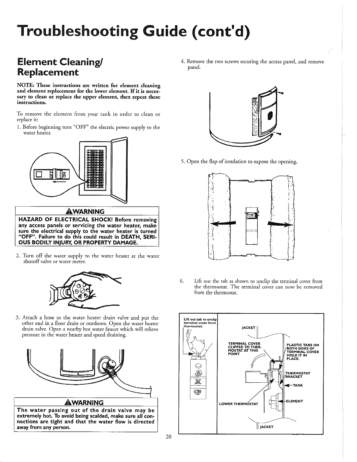
i. Before beginning turn "OFF" the electric power supply to the
water heater.
4. Remove the two screws securing the access panel, and remove
panel.
,_WARNING
HAZARD OF ELECTRICAL SHOCK! Before removing
any access panels or servicing the water heater, make
sure the electrical supply to the water heater is turned
"OFF". Failure to do this could result in DEATH, SERI.
OUS BODILY INJURY,OR PROPERTYDAMAGE.
2. Turn off the water supply to the water heater at the wamr
shutoffvalve or water meter.
3. Attach a hose to the water heater drain valve and put the
other end in a floor drain or outdoors. Open the water heater
drain valve. Open a nearby hot water faucet which will relieve
pressure in the water heater and speed draining.
5. Open the flap of insulation to expose the opening.
if , '
_WARNING !
The water passing out of the drain valve may be
extremely hot.To avoid beingscalded,make sure all con-
nections are tight and that the water flow is directed
away from anyperson.
20
6.
Lift our the tab as shown to unclip the terminal cover from
the thermostat. The terminal cover can now be removed
from the thermostat.
Lift out tab to uncii F
terminal Cover from
thermosta_
)
TERMINAL COVER PLASTIC TABS ON
CLIPPED TO THER- /BOTH SIDES OF
HOSTAT AT THIS TERHINAL COVER
POINT HOLD iT IN
PLACE.
LOWER THERHOSTAT
THERHOSTAT
Troubleshooting Guide (cont'd)
Element Cleaning/
Replacement (cont'd)
WARNING
Replacement elements must (I) be the same voltage and
(2) no greater wattage than listed on the model rating
plate affixed to the water heater.
.
8.
.
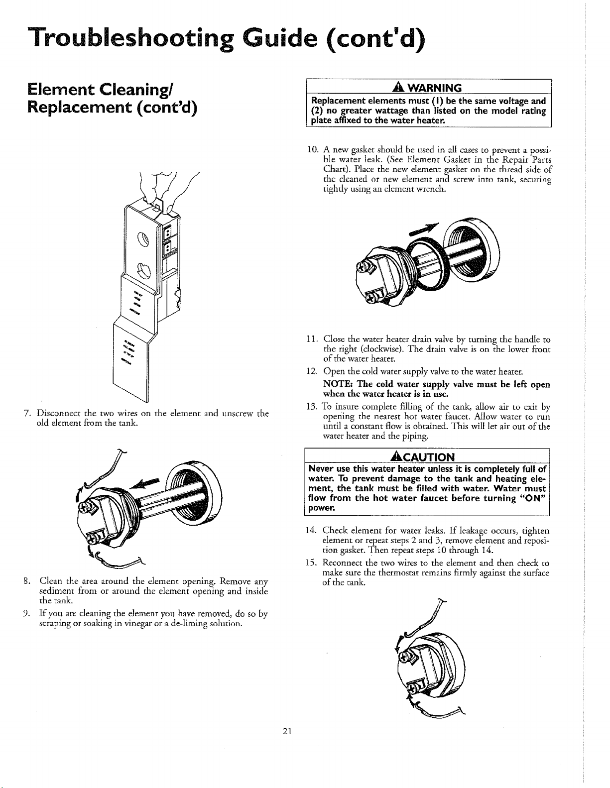
Disconnect the two wires on the elen, ent and unscrew the
old element from the tank.
Clean the area around the element opening. Remove any
sediment from or around the element opening and inside
the tank.
If you are cleaning the element you have removed, do so by
scraping or soaking in vinegar or a de-liming solution.
21
10. A new gasket should be used in all cases to prevent a possi-
ble water leak. (See Element Gasket in the Repair Parts
Chart). Place the new element gasket on the thread side of
the cleaned or new element and screw into tank, securing
tighdy using an element wrench.
11, Close the water heater drain valve by turning the handle to
the right (clockwise). The drain valve is on the lower front
of the water heater.
12, Open the cold water supply valve to the water heater.
NOTE: The cold water supply valve must be left open
when the water heater is in use.
13.
To insure complete filling of the tank, allow air to exit by
opening the nearest hot water faucet. Allow water to run
until a constant flow is obtained. This will let air out of the
water heater and the piping.
ACAUTION
Never use this wate_it is completely full of I
water. To prevent damage to the tank and heating ele- I
merit, the tank must be filled with water. Water must 1
flow from the hot water faucet before turning "ON" i
power. I
14. Check element for water leaks. If leakage occurs, tighten
element or repeat steps 2 and 3, remove element and reposi-
tion gasket. Then repeat steps l0 through 14.
15. Reconnect the two wires to the element and then check to
make sure the thermostat remains firmly against the surface
of the tank.

Troubleshooting Guide (cont'd)
Element Cleaning/
Replacement (cont'd)
16. Replace terminal cover on thermostat and fold insulation
back over the element making sure that the locking tabs on
the terminal cover are in place,
17. Fold the insulation back in place so that it completely covers
the thermostat and element.
18. Replace accesspanel.
19. Turn ;'ON" electricpower to water heater.
Drain Valve Washer
Replacement
NOTE: For replacement, use a _2" x 13A4"x ¼" thick washer
available at your nearest hardware store. For ordering a
replacement washer, refer to the "Repair Parts" section.
1. Before beginning turn "OFF" the electrical power supply to
the waterheater.
_WARNING
HAZARD OF ELECTRICAL SHOCK! Before removing
any access panels or servicing the water heater, make
sure the electrical supply to the water heater is turned
"OFF". Failure to do this could result in DEATH, SERI-
OUS BODILY INJURY, OR PROPERTY DAMAGE.
2, Follow "Draining" instructions, See "Draining" section,
3. Turning counter clockwise, remove the hex cap below the
screw handle.
4, Remove the washer and put the new one in place,
5. Screw the handle and cap assembly back into the drain valve
and retighten using a wrench, DO NOT OVER TIGHTEN,
6. Follow "Filling the Water Heater" instructions in the:
"Installing the New Water Heater" section.
7, Check for leaks.
8. Turn "ON" electric power to the water heater.
_ HANDLEAND
Service
Before calling for repair service, read the Start Up Conditions
and Operational Conditions found in the Troubleshooting
Guide of this manual.
If a condition persists or you are uncertain about the operation
of the water heater, let a qualified person check it out.
Contact SEARS Repair Services
at 1-800-4-REPAIR (1-800-473-7247).
22
• roubleshooting Guide (cont'd)
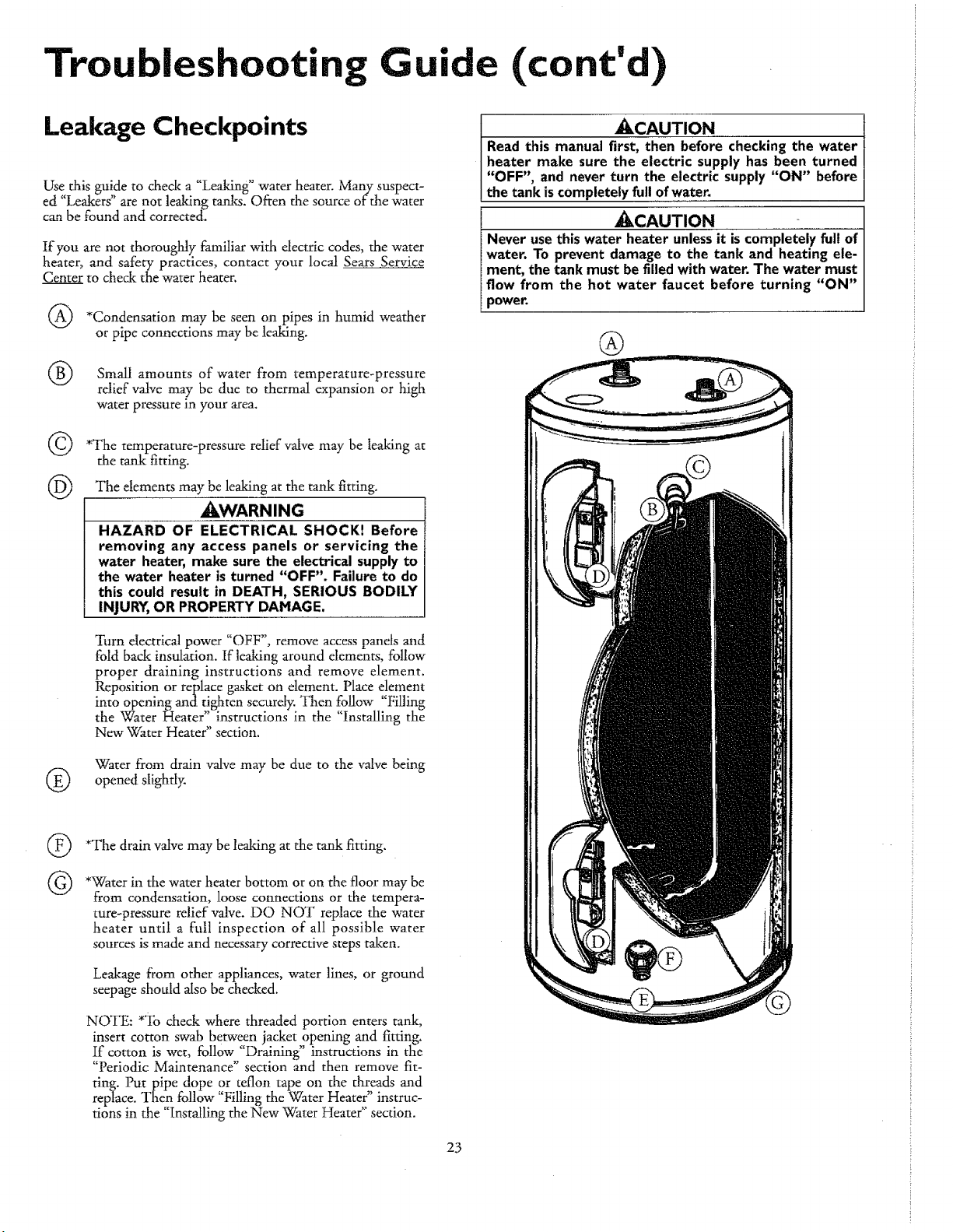
Leakage Checkpoints
Use this guide to check a "Leaking" water heater. Many suspect-
ed "Leakers" are not leaking tanks. Often the source of the water
can be found and corrected.
If you are not thoroughly familiar with dectric codes, the ,#cater
heater, and safety practices, contact your local Sears Service
Center to check the water heater.
*Condensation may be seen on pipes in humid weather
or pipe connections may be leaking.
amounts water temperature-pressure
Small of from
rdief valve may be due to thermal expansion or high
water pressure in your area.
©
@
*The temperature-pressure relief valve may be leaking at
the t_ fitting.
The elements may be leaking at the tank fitting.
_IWARNING
HAZARD OF ELECTRICAL SHOCK! Before
removing any access panels or servicing the
water heater, make sure the electrical supply to
the water heater is turned "OFF". Failure to do
this could result in DEATH, SERIOUS BODILY
INJURY, OR PROPERTY DAMAGE,
Turn electrical power "OFF", remove access pands and
fold back insulation. If leaking around dements, follow
proper draining instructions and remove element
Reposition or replace gasket on element. Place element
into opening and tighten securely. Then follow "Filling
the Water Heater" instructions in the "Installing the
New Water Heater" section.
Water from drain valve may be due to the valve being
(_) opened slightly.
®
©
*The drain valve may be leaking at the tank fitting.
*Water in the water heater bottom or on the floor may be
from condensation, loose connections or the tempera-
ture-pressure relief valve. DO NOT replace the water
heater until a full inspection of all possible water
sources is made and necessary corrective steps taken.
Leakage from other appliances, water lines, or ground
seepage should also be checked.
NOTE: *To check where threaded portion enters tank,
insert cotton swab between jacket opening and fitting.
if cotton is wet, follow "Draining" instructions in the
"Periodic Maintenance" section and then remove fit-
ting. Put pipe dope or teflon tape on the threads and
replace. Then follow "Filling the Water Heater" instruc-
tions in the "Installing the New Water Heater" section.
_CAUTION
Read this manual first, then before checking the water
heater make sure the electric supply has been turned
"OFF", and never turn the electric supply "ON" before
the tank is completely full of water.
®
23
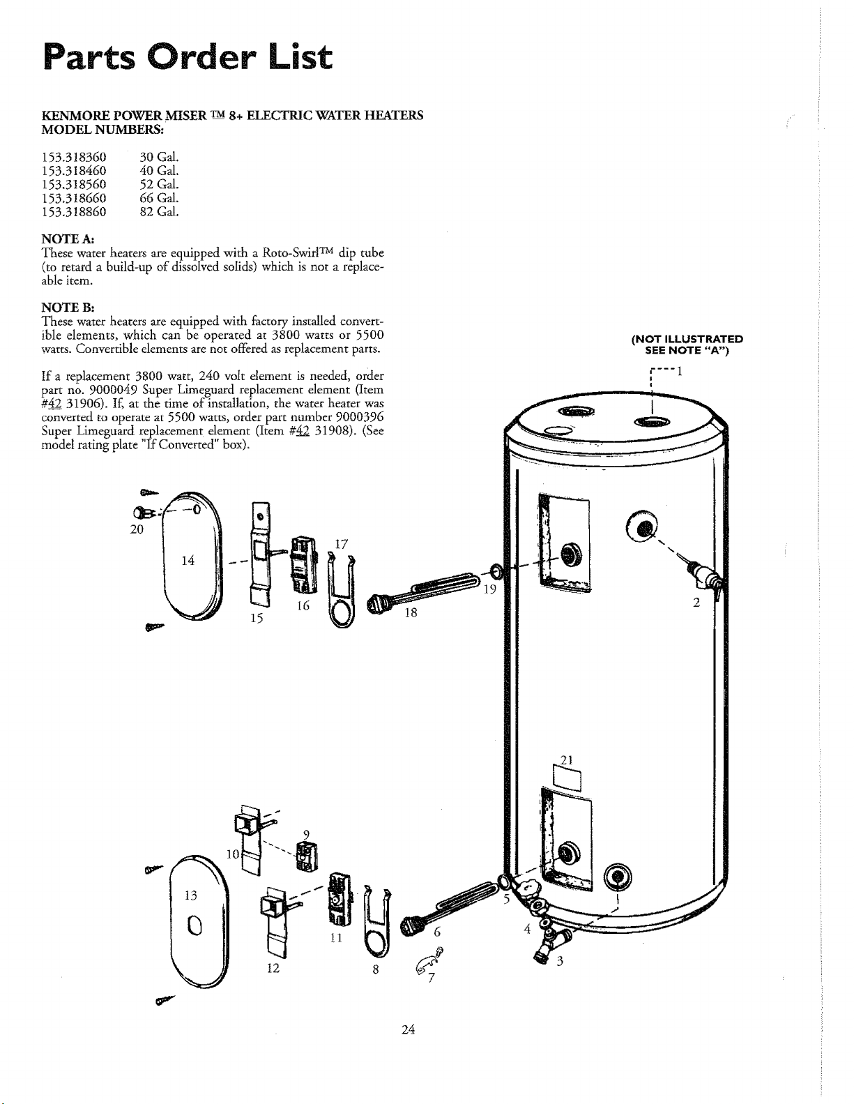
Parts Order List
KENMORE POWER MISER TM 8+ ELECTI_AC WATER HEATERS
MODEL NUMBERS:
153.318360 30G_.
153.318460 40G_.
153.318560 52G_.
153.318660 66Gd.
153.3!8860 82Gd.
NOTE A:
These water heaters are equipped with a Roto-SwirlTM dip tube
(to retard a build-up of dissolved solidi) which is not a replace-
able item.
NOTE B:
These water heaters are equipped with factory installed convert-
ible elements, which can be operated at 3800 watts or 5500
watts. Convertible elements are not offered as replacement parts.
If a replacement 3800 watt, 240 volt element is needed, order
part no. 9000049 Super Limeguard replacement element (Item
#42 31906). If, at the time of installation, the water heater was
converted to operate at 5500 watts, order part number 9000396
Super Limeguard replacement,, ,,element (Item #42__31908). (See
model ranngplate If Converted box).
2O
16
12
i1
6
(NOT ILLUSTRATED
SEE NOTE "A")
t---- 1
t
!
%.
%
2
21
24
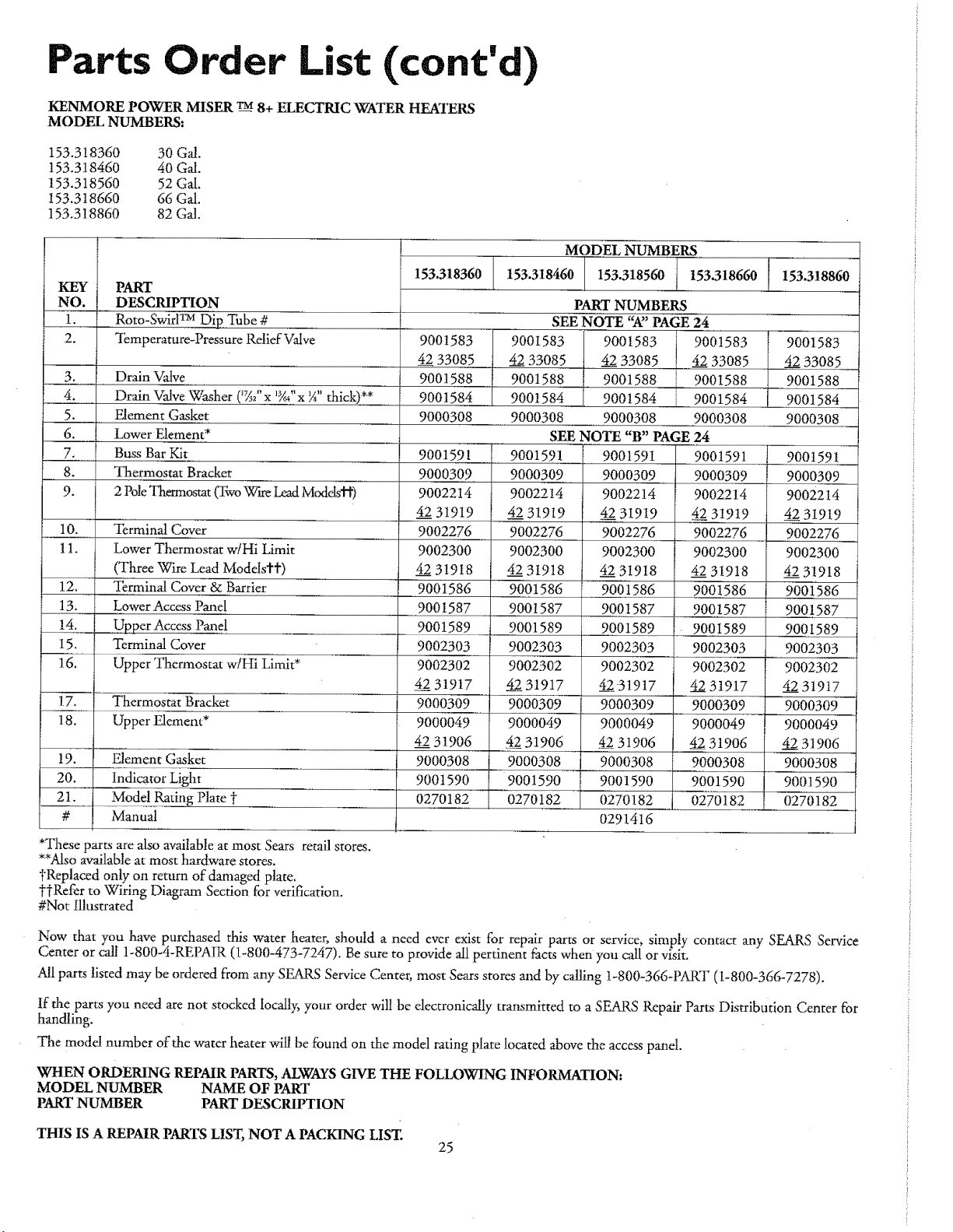
Parts Order List (cont'd)
KENMO1LEPOWER MISER _ 8+ ELECTRIC WATER HEATERS
MODEL NUMBERS:
153.318360 30GJ.
153.318460 40Gd.
153.318560 52Gal.
I53.318660 66 Gal.
153.318860 82 Gal.
KEY PART
NO. DESCRIPTION
1__ Roto-Swirl_ Dip Tube #
2. Temperature-Pressure Relief Valve
3. Drain Valve
__ 4. Drain ValveWasher (%" x 'g_"x _" thick)**
5. Element Gasket
6. Lower Element*
7. Buss Bar Y.it
8. Thermostat Bracket
9. 2PoleThermostat(RvoWireLeadModels'H')
10. Terminal Cover
1!. Lower Thermostat w/Hi Limit
(Three Wire Lead Models€t)
12. Terminal Cover & Barrier
13. Lower Access Panel
14. Upper Access Panel
15. Terminal Cover
16. Upper Thermostat w/Hi Limit*
17. Thermostat Bracket
18. Upper Element*
19. Element Gasket
20. Indicator Light
21. ..... Mode! Rating Plate t
# Manual
*These parts are also availableat most Sears retail stores.
**Alsoavailable at most hardware stores.
_Replaced only on return of damaged plate.
t-tRefer to Wiring Diagram Section for verification.
#Not Illustrated
MODEL NUMBERS
I53.318360 j 153.318460 I 153.318560 l 153.318660 [ 153.318860
9001583
4233085
9001588
9001584
9000308
9001591
9000309
9002214
4231919
9002276
9002300
4231918
9OO1586
9001587
9001589
9002303
9002302
4231917
9000309
9000049
4231906
9000308
9001590
0270182
PART NUMBERS
SEE NOTE "R' PAGE 24
9001583 9001583 9001583
4___233085 4__2233085 4__a233085
9001588 9001588 9001588
9001584 [ 9001584 9001584
9000308 9000308 9000308
SEENOTE"B" PAGE24
t9001591
9000309
9002214
4__a231919
9002276
9002300
4_2231918
9001586
9001587
9001589
90023O3
9O02302
4__2.231917
9O0O309
9000049
4_231906
9000308
9001590
0270182
9001591
900O309
9002214
45 31919
9002276
9002300
4231918
9001586
9001587
9001589
9002303
9002302
42-31917
9000309
9000049
4_2_231906
90O0308
9001590
i 0270182
0291416
9001591
9000309
9002214
4.42231919
9002276
9002300
4231918
9001586
9001587
9001589
90023O3
9002302
4231917
9000309
9000049
42319O6
9000308
9001590
0270182
9001583
4233O85
9001588
9001584
90003O8
9001591
9000309
9002214
4231919
9O02276
9002300
4231918
9001586
9001587
9001589
9O023O3
9002302
4231917
9OOO3O9
9000049
4231906
9000308
9001590
0270182
Now that you have purchased this water hearer, should a need ever exist for repair parts or service, simply contact any SEARS Service
Center or call 1-800-4-REPAIR (i-800-473-7247). Be sure to provide all pertinent facts when you call or visit.
Allparts listed may be ordered from any SEARS Service Center, most Sears stores and by calling 1-800-366-PART (t-800-366-7278).
If the parts you need are not stocked locally,your order will be electronically transmitted to a SEARS Repair Parts Distribution Center for
handling.
The model number of the water heater will be found on the model rating plate located abovethe access panel.
WHEN ORDERING REPAIR PARTS,ALWAYSGIVE THE FOLLOWING INFORMATION.
MODEL NUMBER NAME OF PART
PARTNUMBER PARTDESCRIPTION
THIS IS A REPAIRPARTS LIST, NOT A PACKING LIST.
25

Parts Order List (cont'd)
KENMORE POWER MISER TM8+ ELECTRIC WATER HEATERS
MODEL NUMBERS:
153.318160 30 Gal. Short
153.318260 40 Gal. Short
NOTE A:
These water heaters are equipped with a Roto-SwirlTM dip tube
(to retard a build-up of dissolved solids) which is not a replace-
able item.
NOTE B:
These water heaters are equipped with factory installed convert-
ible elements, which can be operated at 3800 watts or 5500
watts. Convertible elements are not offered as replacement parts.
If a replacement 3800 watt, 240 volt element is needed, order
parr no. 9000049 Super Limeguard replacement element (Item
#4231906). If, at the time of installation, the water heater was
converted to operate at 5500 watts, order part number 9000396
Super Limeguard replacement element (Item #4___2231908). (See
mo_delrating plate "If Converted" box).
5
s
8
(NOT ILLUSTRATED
SEE NOTE "A")
1"-'" 1
1
%.
2
t2
®
26
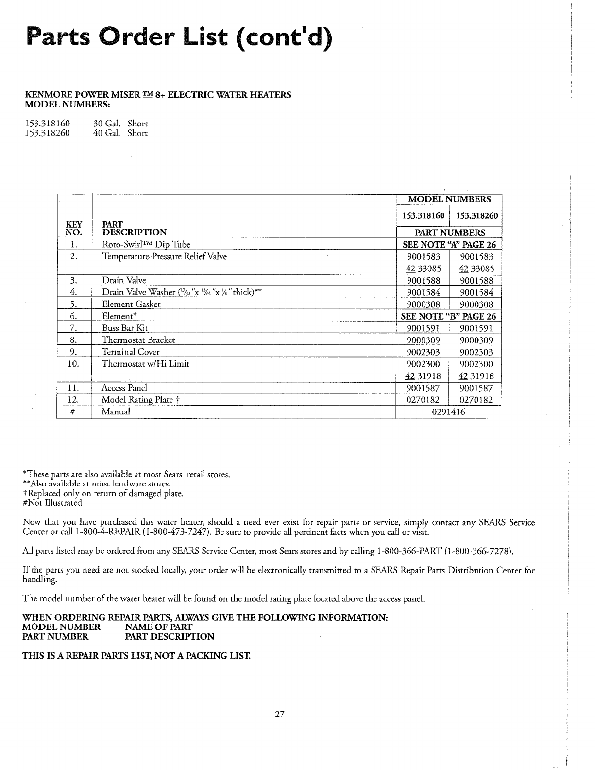
Parts Order List (cont'd)
KENMORE POWER MISER TM8+ ELECTRIC WATER HEATERS
MODEL NUMBERS:
153.3t8t60 30 Gal. Short
153.3t8260 40 Gal. Short
KEY PART
NO. DESCRIPTION
1. Roto-SwirlTM Dip Tube
2. Temperature-Pressure Relief Valve
153.318160 153.318260
9001583
4233085
9001588
9001584
9000308
3. Drain Valve
4. Drain ValveWasher ('7A2% *Y_"x ¼"thick)**
5. Element Gasket
6. Element* SEE NOTE "B" PAGE26
7. BussBar Kit 900159! ' 9001591
8. Thermostat Bracket 9000309 9000309
9. Terminal Cover 9002303 9002303
10. Thermostat w!Hi Limit 9002300 9002300
4231918 4231918
t !. Access Panel 9001587 9001587
12. Model Rating Plate _ 0270182 0270182
# Manual 0291416
PART NUMBERS
SEENOTE"A'PAGE 26
9001583
4233085
9001588
9001584
9000308
*These parts are also available at most Sears retail stores.
**Alsoavailable at most hardware stores.
tReplaced only on return of damaged plate.
#Not Illustrated
Now that you have purchased this water heater, should a need everexist for repair parts or service, simply contact any SEARS Service
Center or call 1-800-4-REPAIR (I-800-473-7247). Besure to provide all pertinent facts when you call or visit.
Allparts listed may be ordered from any SEARS Service Center, most Searsstores and by calling 1-800-366-PART (1-800-366-7278).
If the parts you need are not stocked locally; your order will be electronically transmitted to a SEARS Repair Parts Distribution Center for
handling.
The model number of the water heater will be found on the model rating plate located above the accesspanel.
WHEN ORDERING REPAIRPARTS,ALWAYSGIVE THE FOLLOWING INFORMATION:
MODEL NUMBER NAME OF PART
PARTNUMBER PART DESCRIPTION
THIS IS A REPAIR PARTS LIST, NOT A PACKING LIST.
27
Warranty
About Your Warranty
THE PRICEOF YOURWATERHEATERDOES NOT INCLUDE
A FREE CHECKUP SERVICECALL.On Water Heater tnstalations
ArrangedBySears,Searswarrantsthe installation.
ON INSTALLATIONS NOT MADE BYSEARS AUTHORIZED
CONTRACTORS:
1."fourSearswarrantyappliesto theproduct only.
2. Searsdoesnot warrantthe installation.
3. A chargewill be made on servicecalls due to poor or incomplete
installation.Theseinclude:
a.Adjusting thermostat.
b. Leaks in pipes or fittings.
This manual is in non-technical language. It may help you avoid the
cost of a needless service call. Many service calls really arent needed.
Such aswhen:
1.The electric power is turned "OFF".
2. A water leak is due to loose pipe or connections.
FULLONE YEAR.WARRANTYON WATERHEATER
For one year from the date of purchase, when your Sears Kenmore water heater is installed and operated in accordance with the
instructions in this manual, Sears will:
!. Repair defects in material or workmanship in this water heater, free of charge.
2. Furnish and install a new current model water heater of closest available capacity and quality, free of charge, if a leak occurs in
thetank.
LIMITED WARRANTYON TANKSTHAT LEAK
After one year and through 8 years from the date of purchase, if a leak occurs in the tank, Searswill furnish a new current model
water heater of closest available capacity and quatity. You will be charged for installation.
LIMITED WARRANTY ON PARTS
After one year and through 4 years from the date of purchase, when your Sears Kenmore -waterheater is installed and operated in
accordance with the information in this manual, if a part fails due to a failure in materials or workmanship, Sears will furnish a
replacement part free of charge. You will be charged for labor.
If the water heater is subjected to commercial, institutional, industrial or Other non-residential use (more than 2 families), the
above warranty coyerage for tanks that leak is effective for 2 years from the date of purchase and the above parts warranty is effec-
tive for 1 year from the date of purchase. " " ,
To obtain warranty service, SIMPLY CONTACT THE NEAREST SEARS STORE OR SEARS SERVICE CENTER IN THE
UNITED STATES. This warranty applies only while this product is in use in the United Stares.
This warranty givesyou specific legal rights and you may also have other rights which vary from state to state.
SEARS, ROEBUCK AND CO., Dept. 817 WA, Hoffman Estates, IL 60179
Sears Installation Warranty
In addition m anywarrantyextendedto youon the Searsmerchandise
involved,whichwarrantybecomeseffectivethe date the merchandiseis
installedshould the workmanship of aW Searsarrangedinsrallation
provefaulty within one year,Searswilt, upon notice from you, cause
suchfaultsto be correctedat no additionalcostto you.If youwant this
hearerprofessionally:installedby Searscontactyour SearsSalesperson.
Theywillarrangeforprompt, qualityinstallation.
Parts Ordering Information
Themodd number ofyourwaterheateris foundon themodelrating
plateon the front ofthe waterheater.
Sears Installation Policy
AllinstallationlaborarrangedbySearsshallbeperformedin aneat,
workmanlikemannerin accordancewithgenerallyacceptedtrade prac-
tices.Further,allinstallationsshallcomplywithalllocaltaws,codes
regulationsand ordinances.The customershallalsobe protected,dur-
inginstallation,byinsurancerelatingto propertydamage,Worker's
Compensationand PublicLiability.
Ifyou wantthiswaterheaterprofessionallyinstalledbySearscontact
yourSalesperson.Theywillarrangeforprompt, qualityinstallationby"
Searsauthorizedcontractors.
FOrtherepairorreplacementpartsyouneed
delivereddirectlytoyourhome
Gall7am- 7pro,7daysaweek
1-800-366-PART
(1-800-366-7278)
Forin-homemajorbrandrepairservice
Cat124hoursaday,7daysaweek
1-800-4-REPAIR
(r1-800-473-7247)
1-96
Sears, Roebuck and Co., Hoffman Estates, IL 60 i 79 U.S.A.
0291416-00