Use
&
Care
Guide
Model
No.
153.332420
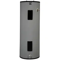
40
Gallon
Tall
Kenmore.
For
potable
water
heating
only.
Not
suitable
for
space
heating.
Not
for
use
in
mobile
homes.
INSTALLER:
Affix
these
instructions
to
or
near
the
water
heater.
OWNER:
Retain
these
instructions
for
future
reference.
FOR
YOUR
SAFETY:
An
odorant
is
added
to
the
gas
used
by
this
water
heater.
ADVERTENCIA
Si
no
puede
leer
o
entender
el
inglés
y
necesita
el
manual
de
instrucciones
en
espafiol,
puede
solicitarlo
al
1-800-821-2017.
NO
TRATE
DE
INSTALAR
U
OPERAR
ESTE
CALENTADOR
DE
AGUA
SI]
NO
ENTIENDE
LAS
INSTRUCCIONES.
No
hacer
caso
de
esta
advertencia
podria
originar
lesiones
graves
o
mortales.
P/N
319357-000
(0810)
Sears
Brands
Management
Corporation,
Hoffman
Estates,
IL
60179
U.S.A.
www.
kenmore.com
www.sears.com
el
WARNING:
If
the
information
in
these
instructions
is
not
followed
exactly,
a
fire
or
explosion
may
result
causing
property
damage,
personal
injury
or
death.
—
Do
not
store
or
use
gasoline
or
other
flammable
vapors
and
liquids
in
the
vicinity
of
this
or
any
other
appliance.
—
WHAT
TO
DOIF
YOU
SMELL
GAS:
e
Donottry
to
light
any
appliance.
e
Do
not
touch
any
electrical
switch;
do
not
use
any
phonein
your
building.
e
Immediately
call
your
gas
supplier
from
a
neighbor’s
phone.
Follow
the
gas
supplier’s
instructions.
e
If
you
cannot
reach
your
gas
supplier,
call
the
fire
department.
—
Installation
and
service
must
be
performed
by
a
qualified
installer,
service
agency
or
the
gas
supplier.
SAFE
INSTALLATION,
USE
AND
SERVICE
Your
safety
and
the
safety
of
others
is
extremely
important
in
the
installation,
use
and
servicing
of
this
water
heater.
Many
safety-related
messages
and
instructions
have
been
provided
in
this
manual
and
on
your
own
water
heater
to
warn
you
and
others
of
a
potential
injury
hazard.
Read
and
obey
all
safety
messages
and
instructions
throughout
this
manual.
It
is
very
important
that
the
meaning
of
each
safety
message
is
understood
by
you
and
others
who
install,
use
or
service
this
water
heater.
This
is
the
safety
alert
symbol.
It
is
used
to
alert
you
to
potential
personal
injury
hazards.
Obey
all
safety
messages
that
follow
this
symbol
to
avoid
possible
injury
or
death.
A
DANGER
indicates
an
imminently
hazardous
situation
which,
if
not
avoided,
will
result
Pas
in
death
or
injury.
WARNING
indicates
a
potentially
hazardous
situation
which,
if
not
avoided,
could
result
7
NNN)
in
death
or
injury.
CAUTION
indicates
a
potentially
hazardous
situation
which,
if
not
avoided,
could
result
7
NTNU,
in
minor
or
moderate
injury.
CAUTION
used
without
the
safety
alert
symbol
indicates
a
potentially
hazardous
ied
situation
which,
if
not
avoided,
could
result
in
property
damage.
ET
Me
All
safety
messages
will
generally
tell
you
about
the
type
of
hazard,
what
can
happen
if
you
do
not
follow
the
safety
message
and
how
to
avoid
the
risk
of
injury.
The
California
Safe
Drinking
Water
and
Toxic
Enforcement
Act
requires
the
Governor
of
California
to
publish
a
list
of
substances
known
to
the
State
of
California
to
cause
cancer,
birth
defects,
or
other
reproductive
harm,
and
requires
businesses
to
warn
of
potential
exposure
to
such
substances.
WARNING:
This
product
contains
a
chemical
known
to
the
State
of
California
to
cause
cancer,
birth
defects,
or
other
reproductive
harm.
This
appliance
can
cause
low-level
exposure
to
some
of
the
substances
included
in
the
act.
IMPORTANT
DEFINITIONS
¢
Qualified
Technician:
A
qualified
technician
must have
ability
equivalent
to
a
licensed
tradesman
in
the
fields
of
plumbing,
air
supply,
venting,
and
gas
supply,
including
a
thorough
understanding
of
the
requirements
of
the
National
Fuel
Gas
Code
as
it
relates
to
the
installation
of
gas
fired
water
heaters.
The
qualified
technician
must
also
be
familiar
with
the
design
features
and
use
of
flammable
vapor
ignition
resistant
water
heaters,
and
have
a
thorough
understanding
of
this
instruction
manual.
*
Service
Agency:
A
service
agency
also
must
have
ability
equivalent
to
a
licensed
tradesman
in
the
fields
of
plumbing,
air
supply,
venting
and gas
supply,
including
a
thorough
understanding
of
the
requirements
of
the
National
Fuel
Gas
Code
as
it
relates
to
the
installation
of
gas
fired
water
heaters.
The
service
agency
must
also
have
a
thorough
understanding
of
this
instruction
manual,
and
be
able
to
perform
repairs
strictly
in
accordance
with
the
service
guidelines
provided
by
the
manufacturer.
¢
Gas
Supplier:
The
natural
gas
or
propane
utility
or
service
who
supplies
gas
for
utilization
by
the
gas
burning
appliances
within
this
application.
The
gas
supplier
typically
has
responsibility
for
the
inspection
and
code
approval
of
gas
piping
up
to
and
including
the
natural
gas
meter
or
propane
storage
tank
of
a
building.
Many
gas
suppliers
also
offer
service
and
inspection
of
appliances
within
the
building.
AWARNING
FIRE
AND
EXPLOSION
HAZARD
Can
result
in
serious
injury
or
death
Do
not
store
or
use
gasoline
or
other
flammable
vapors
and
liquids
in
the
vicinity
of
this
or
any
other
appliance.
Storage
of
or
use
of
gasoline
or
other
flammable
vapors
or
liquids
in
the
vicinity
of
this
or
any
other
appliance
can
result
in
serious
injury
or
death.
Flammable
Vapors
Read
and
follow
water
heater
warnings
and
instructions.
©
Sears,
Roebuck
and
Co.
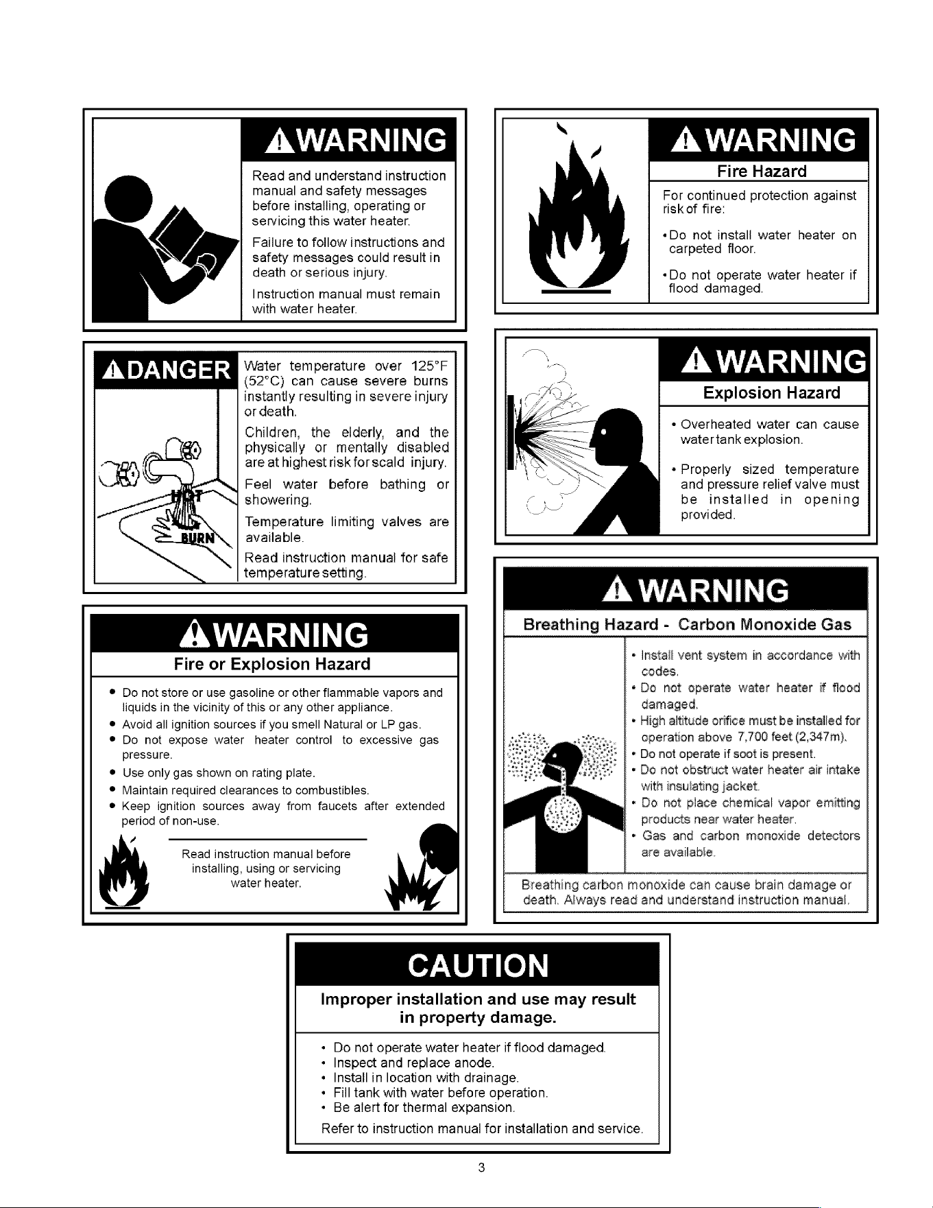
AWARNING
Read
and
understand
instruction
manual
and
safety
messages
before
installing,
operating
or
servicing
this
water
heater.
Failure
to
follow
instructions
and
safety
messages
could
resultin
death
or
serious
injury.
Instruction
manual
must
remain
with
water
heater.
“)
BNIVZARIINe
Fire
Hazard
For
continued
protection
against
risk
of
fire:
«Do
not
install
water
heater
on
carpeted
floor.
«Do
not
operate
water
heater
if
flood
damaged.
ADANGER
Water
temperature
over
125°F
(52°C)
can
cause
severe
burns
instantly
resulting
in
severe
injury
or
death.
Children,
the
elderly,
ana
the
physically
or
mentally
disabled
are
at
highest
risk
forscald
injury.
Feel
water
before
bathing
or
showering.
Temperature
limiting
valves
are
available.
Read
instruction
manual
for
safe
temperature
setting.
A
WARNING
Explosion
Hazard
*
Overheated
water
can
cause
water
tank
explosion.
*
Properly
sized
temperature
and
pressure
relief
valve
must
be
installed
in
opening
provided.
AYES
Fire
or
Explosion
Hazard
pressure.
period
of
non-use.
/
Do
not
store
or
use
gasoline
or
other
flammable
vapors
and
liquids
in
the
vicinity
of
this
or
any
other
appliance.
@
Avoid
all
ignition
sources
if
you smell
Natural
or
LP
gas.
®
Do
not
expose
water
heater
control
to
excessive
gas
@
Use
only
gas
shown
on
rating
plate.
®
Maintain
required
clearances
to
combustibles.
®
Keep
ignition
sources
away
from
faucets
after
extended
Read
instruction
manual
before
installing,
water
heater.
using
or
servicing
A
WARNING
Breathing
Hazard
-
Carbon
Monoxide
Gas
«
Install
vent
system
in
accordance
with
codes.
*Do
not
operate
water
heater
if
flood
damaged.
*
High
altitude
orifice
must
be
installed
for
operation
above
7,700
feet
(2,347m).
«
Do
not
operate
if
soot
is
present.
*
Do
not
obstruct
water
heater
air
intake
with
insulating
jacket.
*
Do
not
place
chemical
vapor
emitting
products
near
water
heater.
*»
Gas
and
carbon
monoxide
detectors
are
available.
Breathing
carbon
monoxide
can
cause
brain
damage
or
death.
Always.
read
and
understand
instruction
manual.
CAUTION
Improper
installation
and
use
may
result
in
property
damage.
Do
not
operate
water
heater
if
flood
damaged.
Inspect and
replace
anode.
Install
in
location
with
drainage.
Fill
tank
with
water
before
operation.
¢
Be
alert
for
thermal
expansion.
Refer
to
instruction
manual
for
installation
and
service.
TABLE
OF
CONTENTS
SAFE
INSTALLATION,
USE
AND
SERVICE
0.0.0.0...
cccccccecceesceescenecess
esses
ceteceeerteceetereeereeereeeeseeretererteetinees
2
SAFETY
PRECAUTIONS.
0.0.0.0...
ccccccecceeccsecen
cesses
sees
ceeesesssrsesresceteceeseresereeeeeeeeeeteeeieeeeeeteeesieeesststsseesseesaeees
2-3
PRODUCT
WARRANTY
...........:::ccccccccsecceecceeeeeesseesseesseesseeaeeesseeseeesseeseeaaseaseaaaeaaceeaseaaaeaaseesaeasaeaseeecesceeseeeseeeees
6
CUSTOMER
RESPONSIBILITIES
0.00.
.oiccccccceccceeccnecce
cers
cerssenserssseescsscescetsceeseeeeceteresereeereeeretererenstisssiees
7
PRODUCT
SPECIFICATIONS
o.oo...
ccecceecceceeeeeeeeeeeaeeeseeeseeeseeeaeeaaeeaseaaaeeaaeaaseasaeaaaeeaeeaseeasesaaeeceesceeceeeees
8
MATERIALS
AND
BASIC
TOOLS
NEEDED...
ccccccecccceee
eens
eeeeeeeeeeeeaeeaaeeaaeeeaeeaseesaeeeseeseeeeeeeaeeeaeeees
9
TYPICAL
INSTALLATION
0.0...
cc
ccccccccccccccc
cece cece cece cece
cee
eeeeeeeeeeeeeeeeeeeeeeeeeeeeeeeeeeeeeeeeeeeeeeeeeceeeeeeeceeeceretittnttnninnss
10
IMPORTANT
INFORMATION
ABOUT
THIS
WATER
HEATER.
...............cccccccccceccceceeecceeececeeeceeeceeecesecceeceneess
11
Installation
CHeCKIISt
0...
cc
cece
cee
cece
nee
ee
cette
eee
cette
tne
a
ae ae ee
eee
tree
et
tec
aa
aes
ease
eee
ee
eee
c
cea
caaaeeeeeeeeeseseccciccaeseeeeeeeeeesetieee
11
INSTALLATION
INSTRUCTIONS
0.00...
cceccccecccccececeeececeseceaeeeseececesecesecesecesecceeceseceeececceseceseceessesseeeeeess
12-15
Removing
the
Old
Water
Heater...
cccccccccccceceeeeeeeeeaeeeeee
eee
ee
esses
ee
eeeeeeeeeeeeeeeeeeeeeeeeeeeaeaeseaeasaeeeeaeseeeaeeeeesesesenenes
12
Location
REQUIFEMENHS
...........ccccccccseesesesecececceeeeeeeeeeeeeeeseeaeseaaeseseeeeess
sess
cecEceEeEEeeASASAAeEeEeAseseseanaususaaaaaeaaaaaaeaeneneseeeees
13
‘ST
(0s
Me
lorc
|e)
9
eee
13
INSUlation
Blankets...
cece
eee
eecee
cece
ce
ee
ce
eee eee
tree
teen
ae
ae
eee
ee
eee
teen
te
cea
aaaeaeeeeeeeeeee
cece
ceaaaeeeeeeeeeeeseececqcacaeeeeeeeeeeeenteess
14
Clearances
and
ACCEeSSIDIity
0.0...
ccccccccccccecee
esas
ee
eeeeee
eee
eeeeeeeeeeeeeeeeeeeeeeeeeeeeeseseesesseessee
esse
eases
eeeeeeeeeeseseneneneess
14-15
Filling
the
Water
Heater...
ccc
ccccccccssessssseceeeeeeeeeeeeeeeeeeeeseeseseaaeeaeeeeeeeeeeeeeceeeeeeeseeeeeeeeseseeeeceeeesesaeaeaeaeaeaasnsnsnsesesees
15
CT
ANS
S10
|
od
ad
cc
15-16
GAS
REQUIFEMENS
...........cccccccccccecececceceeeeeeeeeeeeeeaeee
eee
eeAsAsAAHAHs
EE
cEEcEEEEEEEEESE;EAS;E;;E;A;GHGHGEAAAAGASASASAA;AA
GASES
SEE
EESEEEESERESEHEEEEES
15
GAS
PIPING
.....
ccc
ecccceeceeeeeeeeeeeececeeeeeeeeeeeeeeeeeeeee
ae
Gea
HAHAHAHAHAHA
SE
CEEcEEEEEEESESE;E;S;;A;E;ASGHGHGAAAAHGEGEGAAAAA
SAGA
SA
SESE
ESEEEEEEESESEHEEEEEEES
15
GAS
PLOSSUIC
oo.
ccccccec
cece
cee
cececec
eee
ceeeceeeeee
ete
ce
aeaaeaeeeeeeeeeeeteeccaeaaeeeeeeeeeeeeeseececceeaaececeeeeeeeseccceecaeeeeeeeeeeeeesesscacassaeeeeeees
16
GaS
PreSSure
TCStiNG..........ccccccccccccccceceeceeeeeeeeeeeeeee
eee
ee
eases
sHsHs
cece
EcEEEEEEEEESEEE;SAEA;E;EAGHGH
GE
GHAAGA
SASS
SAA;AA
SAGAS
SEs
Ea
EES
EEEESEFEEEHEEEEES
16
LP
Ga
OMY...
ccc
cece
cee
cccenee
cece
eee
etree
eee
eee
eae eee
e
eee eee
ee te
cea
aa ae
cae
eeeeeee
ences
ceaaaaesaeeeeeeeeeeececceeeeeeeeeeeeseeseccccsaseeeeeeeeeeeneeees
16
COMBUSTION
AIR
SUPPLY
&
VENTILATION
...00..00
o.oo
eecceeeeceeceeeceeeceeeceseesetereeseesseeteeeteeeeetetsetseeeseeess
17-20
UNCONFINEW
SPACE...
ccc
cccccceeseeseeeneeececeeeeeeeeeeeeeeeeeeeeeeeeeeeaeeeeeesess
ec
00c0ce0cCeceeeeeASAHEAAEEAGEGEG
AA
AA
GAA
GA
GAG
a
GAGA
GAGA
GAG
SG
ESE
EEES
17
O%0)
all
a[=16
IRs)
6c-
(6.
-
cnr
17
All
Air
from
Inside
the
Building
............cccccccccccecscseceeececeeeeeeeeeeeeeeeeeaeaeaeseeeeeeeeeeee
cscs
ecececeeeeeeeeeeeeeseeeeseeeseseeaeaeaaaaaaaaea
17-18
All
Air
from
OUtGOOLS..0
0.
ccc
cece cece
ce
ecce
eee
e
eee
cette
eet
e
ene
ae
ee
eee eee
ee
eect
cea
aaaeeeeeeeeeeeee
tec
eecccaeaeeeeeeeeeeeeeseesicncieeeeeeeeeeeteee
18
Louvers
And
Grills
22.2...
cece
cee
ee
eee
ceceee
eae
ee
eee
ee
eeeee
eee
ce
aaaeaaeceeeeeeeeceg
ca
ccaecaeeeeeeeeeeeeesecscceeeeeeeeeeetetsecsicaeaeeeeeees
18-19
Vent
Pipe
SyStem
oo...
cccccccccccccccceeeeeeee
esas
eases
sees
ee
08cEcEEEEEEEEE;EEEA;E;AA;E;HGEGAAGAAAAAAGAG
GEE
SESEcEEESESESESESESEEEARASAHAEAHEN
aE
aH
ana
aa
Honea
19
Draft
Hood
Installation
0.00...
ccc
cee
cececceee
cece
eee
cette
eee
e
cee
ae
eee
eeeeeeeeeee
cece
aaaaeaeeeeeeeeeeeceesecceeaaeeeeeeeeeeeesecscacieeeeeeeeeesenenee
19
Mele
ad
Okc)
4
—
eee
n
19
AV(<1
a]
O70)
0]
016:
(0)
kee
19-20
CHIMNEY
CONNECTION.
.........cccccccccccccccceceeceeeeeeeeeee
ee
ae
eee
ee
ees
sHsHHHs
cE
cEEcEEEEEEESESE;EASAEA;A;AAGHGHGAGAAHAASAASH
SESE
ESEEEESEEEEECEEEEEEFEEEHEHEEES
20
Vertical
Exhaust
Gas
Vent
..........ecccccccccccececeeeeeeeeeceecaaeceeeeeeeeeeecccaeaaeeeeeeeeeeeeeceeseccaecaeeeeeeeeeresecccuecaeeeeeseeeeeeetenennsieeas
20
WATER
SYSTEM
PIPING
Lo...
occ
ccccccccccccc
cece cece cece
eee
e
cece
eee
eeee cece cece
eeeeeeeeeeeeeeeeeeeeeeeeeeeceeeeeeseeeeeeeeeeesenssenscenaes
21-22
PIPING
INSTA
ATION...
ec
ccceeeeeeeeeeseeeeeeeeeeeeeeeeeeeeeeeeeeeeeaeeea
ae
ee
sessAsAH
GEESE
SECEEESESEAEASASAEAEEEEEAEASEEGEGEGEG
GAGE
AGA
GA
GAGA
AGE EEEEEES
21
Closed
Syster/Thermal
Expansion
........ccccccccccccccccssssssssesseseseesceeeeeeeeeeeeeeeeeeeeeeeeeeeeaeaesesesseeeeeee
eee
eeeeeeeeeeeeesesesenenenes
22
Temperature
and
Pressure
Relief
Valve
...........cccccccccscccececcceeeceeeeeeeeeeeeeeeeeeeeeeeeeeeeeeeeseeceseceeeseeeeseeeeeseeeseeeeenesauaeaaaaaaas
22
T&P
Relief
Valve
and
Pipe
INSUIAtION.........
ccc
cccceecseseeecececeeceeeeeeeeeeeeeeeeeeaeseaeeeeeeeeee
cece
ce
eeeseseseseseeeeeesusesesaeaeaeaeaeansasneses
22
OPERATING
YOUR
WATER
HEATER.
........cccccccceee
cette
teeter center
tee
eeeeneeeeeeeseeeeeeeeeseneeeenneeeeneeeeeaaes
23-25
LIGNtiNg
INSTPUCTIONS
....
cece
ceeeeeeseseeeceeeeeeeeeeeeeeeeeeeeeeeeeaeaeaaa
eee
eeesssH
CEH
cEcEcEEESEEEAEASESAAAEAEGHAEAGeEsEaHsesaaaaaaaaaaaaaaeaesseeees
23
©
at=101.4]
616s
tals
|
ce
24
Burner
FIAMES
...........ccecceeccecee
cee
ee
cee
cece
eee
ceee
ae
aeeeeee
eee
ee
ete
caeaaeaeeeeeeeeeee
ce
caeeaeaaeceeeeeeeeeeeseccccaeeeeeeeeeeseeseccccsieseeeeeeeeeenenees
24
Emergency
Shut
Down
........cccccccccccccesssssscsesscececeeceeeeeeeeeeeseeeeseseaeseaeaeeeeeeee
eee
eceseeeeeseeeeeeeeeeeeeesaeeeesesaeaeaeaaaeaaeasnsnsssesees
24
Water
Temperature
REQulation
.........ccccccccccccsccssseeseseeeceeeeceeeeeeeeeeeeeeeeeeae
ae
see
eaeee
esse
cecececeeeeeeeeeeeeeeeeseneeenenauaeanaaanaaea
24-25
SERVICE
AND
ADJUSTMENT
.........0..
ccc
cccecceecceeeeeeeeeeceeseeeeceeceececreeeeeeeeeeeeeeeeeeeeeeteesetessetiseeseeesseesisseens
26-28
Vent
System
INSPeCtION
oe
cccccccccce
ee ee
eee
eeee
sees
eee
ceeeeeeeeeeeeeeeeeeeeeeeeeeee
ease
eee
esess
GCG
CH
ceceEeSEEESESESeEEEEARASASAHEEENaHaHaH
aaa
aaaea
26
Burner
INSPECTION.
0...
cccccccceseeeseseeseseeecececeeeeeeeeeeeeeeeeeeeeeaeaea
ae
ee
eeeeesss
SE
EcEcEcEEESEEEEEASASAEAEEAGEAEASEEGEGEGEG
as
GAA
aaGA
GaGa
aa
ESE
EEEEE
ES
26
Burner
Cleaning
.....
ccc
ccccccccccccccseseseeeeseeeeecececeeeeeeeeeeeeeeeeeeeeeaeaea
aa
ee
eeeesess
ee
0c0cEcEEeCeEEAEASASAAEEEEGEAEASEEGEGEGEG
GAGA
A
GAAA
GAG
AG aa
SESE
EEEES
26
HOUSEKEEPING
0...
ccc
cece
cee
ee
eee
eeee
esse
eeeeeeeeeeeeeeeeeeeeeeeeeeaeaeeea
ae ae
eessAsAA
GEE
SEcEcEEESEEEAEASESAEAEEAGEAEAEeEGHGEGEG
AA GA
AAA
GAGA
GAG
aaESEEEEEES
27
Anode
ROd
INSPECTION
0.2...
ccccccccceescessenenececeeeeeeeeeeeeeeeeeeeeeaeaeeeseaeeeeeesess
cscs
ececececeeeeeceeeceeeeseeeeesesusaeaeaeaeaaaaaasaeasseseees
27
Temperature-Pressure
Relief
Valve
Operation
..........ccccccccccccccccccecceeeeeeeeeeeeeeeeeeeeeeeeeseeeececeeeeeeeeeeeeceeeeeeeseeenesaeaesnanaaea
27
Draining
ANd
FIUSHING
.............c
cc
ccecesecececsecececceceeeeeeeeeeeeeeeeaeaeaeeeeeeeeeeee
cee
eeeeeceseeeeeeeeeeeesesesusaeaeesesaeaeaeaeaaaeeasneseseeeess
27-28
SOPVICE
oo.
eeccececccccne
cee
ee
eee
ce
eee
ee
cee
ea ae
ae
eee eee
eeeeeee
cece
aeaaeeeeeeeeeeeeecee
ce
ceaeaaeaeeeeeeeeeeeseccaaececeeeeececcccceecaeeeeeseeeeesesenccecussaeeeeeees
28
MAINTENANCE
OF
YOUR
WATER
HEATER........0....0..cccccecceeecseceeeeseeeseecseeseeeceeaaeeeceeeaeeeaeeeaeeeaeeeeceseeeaes
29-32
Replacement
Parts
........ccccccccccccsssssssesesecececeeceeeeeeeeeeeeeeeeeeaeseaaeaeeeeeeeee
esas
seseceeeseeeeeeeeeeeeeeesuseseaeeeaesesaaaeasaeaeageasaeneseeeees
29
External
Inspection
&
Cleaning
of
the
Base-Ring
Filter
o.oo.
cccccccsssssseseseceeeeeeceeeeeeeeseseeeeeaeaeaeauseaessseaeenseeesesees
29
Removing
the
Manifold/Burner
ASSEMDIY...........cccccccccccccecceceeeseeeeeeseseessesececeeceeeeeeeeeeeeeseseseuseseaaeaeeeaeaeaeseaeaeeneneseeeess
29
Removing
the
Burner
from
the
Manifold/Burner
ASSEMDIy
...............ccccccsceecesececeececeeeeeeeseseesesesusaeaeseaeaeseesseeeeeeeeees
29
Replacing
the
Thermocouple
..............ccccccccccccccccccececeeeeeeeaeaeaeseseeeeeseeeecseeeeeceeeeeeeeeeeeeeessesesaeaeaeseaeaeaeaeaeaaeasneseseeeees
29-30
Replacing
the
Pilot/
Pilot
Tube
ASSEMDIY
0.0...
ccccccccccecceseeeseeseeesesseeeeseececeeeeeeeeeeeeeeeeseeeeseseseassaeaeasasaeseaeaeeneneseeeees
30
Cleaning
the
Combustion
Chamber
and
FIaMe@-arreStOr
..........cccccccccccceccccecceceeeeeeeeeaeaeaeaeseaeeeseeeeeseeeeeeeeeeeseseseseseneees
30
Replacing
the
Manifold/Burner
ASSEMDIY
0.0...
ccccccccccccccceceeeseeeseeseeeeseseseceeeceeeeeeeeseeeeeseeessesesuaaeseseasaeaeaeseaeensneseeeess
31
Piezoelectric
Igniter
SYSteM
...........cccccccccccceccecccecceeeeeeeeeeeaeseaaeeeeeseseseeeseeeeceeeeeseeeeeeeeeeeeeeseesesusaesaesusaeasaeaeaeaasneneneseeeees
31
Testing
the
Igniter
SYStem
0...
ccc
ceseseeeeeeeeeeeeeeeeeeeeeeeeeeeeeeeeeeeeeee
eases
eeeAsAH
SHC
cEcEcEEESESESESeEEEeASAeASAHEHENGH
aH
aH
ananaaea
32
Removing
and
Replacing
the
Gas
Control
Valve/Thermostat
..............:ccccccccseseceececeeeeeeesesesseseeesaeaeaeseaeeeesseeseseneeeess
32
FVIR
System
Operational
CHecklisSt
.............ccccccccccccccceceeeececeeeeeeeeeeeeeeeeeee
sees
eececeeeseseseeeseeeeeeseeaeaessaeaeaeaeaeseeesnsnsesesees
32
TROUBLESHOOTING
GUIDE
2.0.2...
ccc
ccc
cece cece cece cece cece cece cece cece cece cece
eeeeeeeeeeeeeeeeeeeeeeeeeeeeeeeeeeeseeteeeesentenens
33-35
‘S)
r=
[ams
©)
68
O76)
816]
116)
8
|:
ee
33-34
©
Jel-1e-11(6)st=|
Oxo)
a16|11(6)
8:
re
34-35
TROUBLESHOOTING
CHART
.........ccccccccccccccccccccee
cece cece cece
ee
eeeeeeeeeeeeeeeeeeeeeeeeeeeeeeeeeeeeeeeeeeceseceeeceeeceeecenenns
36-37
PILOT
LIGHT
TROUBLESHOOTING
FLOWCHART................ccccccccccecccecccecececececececceeceeceescececeeecessceescesceeeees
38
PARTS
ORDER
LIST
00.00...
ceceeccceecceeeeeeeeeeceeeceeeseeeaeeeseaaaeeaseaaaeeaseaaaeeaseasaeaaeeaaeeaaeeaaeasaeeaaeaaaecceecceeceesess
40-41
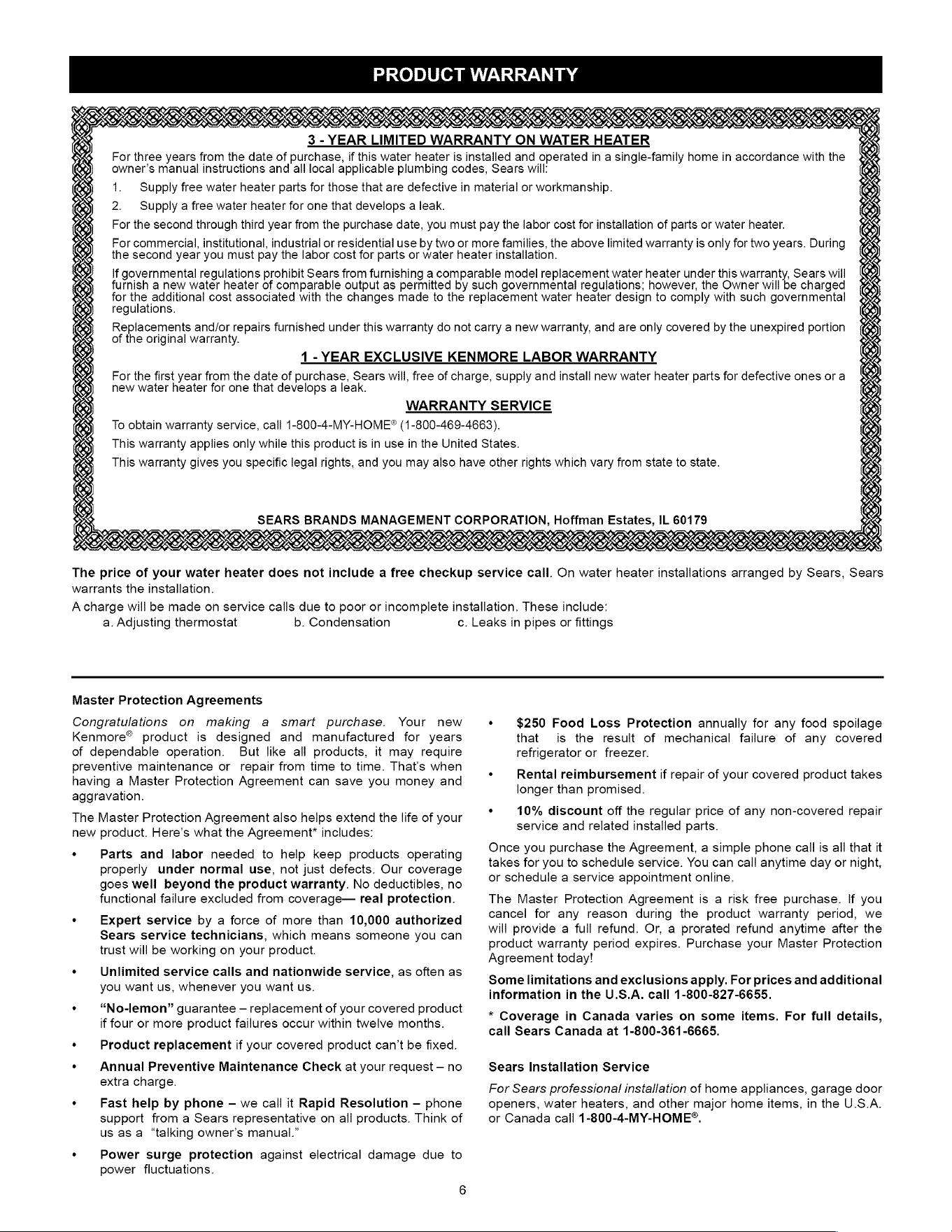
PRODUCT
WARRANTY
3.-
YEAR
LIMITED
WARRANTY
ON
WATER
HEATER
For
three
years
from
the
date
of
purchase,
if
this
water
heater
is
installed
and
operated
in
a
single-family
home
in
accordance
with
the
owner’s
manual
instructions
and
all
local
applicable
plumbing
codes,
Sears
will:
1.
Supply
free
water
heater
parts
for
those
that
are
defective
in
material
or
workmanship.
2.
Supply
a
free
water
heater
for
one
that
develops
a
leak.
For
the
second
through
third
year
from
the
purchase
date,
you
must
pay
the
labor
cost
for
installation
of
parts
or
water
heater.
For
commercial,
institutional,
industrial
or
residential
use
by
two
or
more
families,
the
above
limited
warranty
is
only
for
two
years.
During
the
second
year
you
must
pay
the
labor cost
for
parts
or
water
heater
installation.
If
governmental
regulations
prohibit
Sears
from
furnishing
a
comparable
model
replacement
water
heater
under
this
warranty,
Sears
will
furnish
a
new
water
heater
of
comparable
output
as
permitted
by
such
governmental
regulations;
however,
the
Owner
will
be
charged
for
the
additional
cost
associated
with
the
changes
made
to
the
replacement
water
heater
design
to
comply
with
such
governmental
regulations.
Replacements
and/or
repairs
furnished
under
this
warranty
do
not
carry
a
new
warranty,
and
are
only
covered
by
the
unexpired
portion
of
the
original
warranty.
1-YEAR
EXCLUSIVE
KENMORE
LABOR
WARRANTY
For
the
first
year from
the
date
of
purchase,
Sears
will,
free
of
charge,
supply
and
install
new
water
heater
parts
for
defective
ones
ora
new
water
heater
for
one
that
develops
a
leak.
WARRANTY
SERVICE
To
obtain
warranty
service,
call
1-800-4-MY-HOME®
(1-800-469-4663).
This
warranty
applies
only
while
this
product
is
in
use
in
the
United
States.
This
warranty
gives you
specific
legal
rights,
and
you
may
also
have
other
rights
which
vary
from
state
to
state.
SEARS
BRANDS
MANAGEMENT
CORPORATION,
Hoffman
Estates,
IL
60179
LESS
US
OTS
OER
ISD
ISIS
IRR
EROS
FRIIS
ISIS
ISOS
SSSR
ROTO
NARI
BERBSCBRERSREAIEBR
REESE
ORO
OOOO
RIONER
The
price
of
your
water
heater
does
not
include
a
free
checkup
service
call.
On
water
heater
installations
arranged
by
Sears,
Sears
warrants
the
installation.
A
charge
will
be
made
on
service
calls
due
to
poor
or
incomplete
installation.
These
include:
a.
Adjusting
thermostat
b.
Condensation
c.
Leaks
in
pipes
or
fittings
Master
Protection
Agreements
Congratulations
on
making
a
smart
purchase.
Your
new
Kenmore®
product
is
designed
and
manufactured
for
years
of
dependable
operation.
But
like
all
products,
it
may
require
preventive
maintenance
or
repair
from
time
to
time.
That's
when
having
a
Master
Protection
Agreement
can
save
you
money
and
aggravation.
The
Master
Protection
Agreement
also
helps
extend
the
life
of
your
new
product.
Here’s
what
the
Agreement*
includes:
.
Parts
and
labor
needed
to
help
keep
products
operating
properly
under
normal
use,
not
just
defects.
Our
coverage
goes
well
beyond
the
product
warranty.
No
deductibles,
no
functional
failure
excluded
from
coverage—
real
protection.
.
Expert
service
by
a
force
of
more
than
10,000
authorized
Sears
service
technicians,
which
means
someone
you
can
trust
will
be
working
on
your
product.
°
Unlimited
service
calls
and
nationwide
service,
as
often
as
you
want
us,
whenever
you
want
us.
.
“No-lemon”
guarantee
—
replacement
of
your
covered
product
if
four
or
more
product
failures
occur
within
twelve
months.
.
Product
replacement
if
your
covered
product
can’t be
fixed.
.
Annual
Preventive
Maintenance
Check
at
your
request
—
no
extra
charge.
.
Fast
help
by
phone
-
we
call
it
Rapid
Resolution
—
phone
support
from
a
Sears
representative
on
all
products.
Think
of
us
asa
“talking
owner’s
manual.”
.
Power
surge
protection
against
electrical
damage
due
to
power
fluctuations.
6
.
$250
Food
Loss
Protection
annually
for
any
food
spoilage
that
is
the
result
of
mechanical
failure
of
any
covered
refrigerator
or
freezer.
.
Rental
reimbursement
if
repair
of
your
covered
product
takes
longer
than
promised.
.
10%
discount
off
the
regular
price
of
any
non-covered
repair
service
and
related
installed
parts.
Once
you
purchase
the
Agreement,
a
simple
phone
call
is
all
that
it
takes
for
you
to
schedule
service.
You
can
call
anytime
day
or
night,
or
schedule
a
service
appointment
online.
The
Master
Protection
Agreement
is
a
risk
free
purchase.
If
you
cancel
for
any
reason
during
the
product
warranty
period,
we
will
provide
a
full
refund.
Or,
a
prorated
refund
anytime
after
the
product
warranty
period
expires.
Purchase
your
Master
Protection
Agreement
today!
Some
limitations
and
exclusions
apply.
For
prices
and
additional
information
in
the
U.S.A.
call
1-800-827-6655.
*
Coverage
in
Canada
varies
on
some
items.
For
full
details,
call
Sears
Canada
at
1-800-361-6665.
Sears
Installation
Service
For
Sears
professional
installation
of
home
appliances,
garage
door
openers,
water
heaters,
and
other
major
home
items,
in
the
U.S.A.
or
Canada
call
1-800-4-MY-HOME®.
CUSTOMER
RESPONSIBILITIES
Thank
You
for
purchasing
a
Kenmore
water
heater.
Properly
installed
and
maintained,
it
should
give
you
years
of
trouble
free
service.
If
you
should
decide
that
you
want
the
new
water
heater
professionally
installed
by
Sears
call
1-800-4-MY-HOME®.
They
will
arrange
for
prompt,
quality
installation
by
Sears
authorized
contractors.
Abbreviations
Found
In
This
Instruction
Manual:
*
CSA-
Canadian
Standards
Association
*
ANSI-
American
National
Standards
Institute
*
NFPA
-
National
Fire
Protection
Association
*
ASME
-
American
Society
of
Mechanical
Engineers
*
GAMA
-
Gas
Appliance
Manufacturers
Association
Important
Information
About
This
Water
Heater:
This
gas
water
heater
was
manufactured
to
voluntary
safety
standards
to
reduce
the
likelihood
of
a
flammable
vapor
ignition
incident.
New
technology
used
in
meeting
these
standards
makes
this
product
more
sensitive
to
installation
errors
or
improper
installation
environments.
Please
review
the
Installation
Checklist
found
at
the
end
of
the
installation
instructions
section
and
make
any
required
installation
upgrades
or
changes.
This
manual
contains
instructions
for
the
installation,
operation,
and
maintenance
of
the
gas-fired
water
heater.
It
also
contains
warnings
through
out
the
manual
that
you
must
read
and
be
aware
of.
All
warnings
and
all
instructions
are
essential
to
the
proper
operation
of
the
water
heater
and
your
safety.
Since
we
cannot
put
everything
on
the
first
few
pages,
READ
THE
ENTIRE
MANUAL
BEFORE
ATTEMPTING
TO
INSTALL
OR
OPERATE
THE
WATER
HEATER.
*
The
installation
must
conform
with
these
instructions
and
the
local
code
authority
having
jurisdiction.
In
the
absence
of
local
codes,
installations
shall
comply
with
the
following:
In
the
United
States:
The
National
Fuel
Gas
Code ANSI
Z223.1/
NFPA
54.
This
publication
is
available
from
the
Canadian
Standards
Association,
8501
East
Pleasant
Valley
Rd,
Cleveland
Ohio
44131,
or
The
National
Fire
Protection
Association,
1
Batterymarch
Park,
Quincy,
MA
02269.
¢
If
after
reading
this
manual
you
have
any
questions
or
do
not
understand
any
portion
of
the
instructions,
call
the
Sears
Service
Center.
*
Carefully
plan
the
place
where
you
are
going
to
put
the
water
heater.
Correct
combustion,
vent
action,
and
vent
pipe
installation
are
very
important
in
preventing
death
from
possible
carbon
monoxide
poisoning
and
fires.
See
Figure
1.
*
Examine
the
location
to
ensure
the
water
heater
complies
with
the
Installation
Instructions
section
in
this
manual.
¢
For
California
installation,
this
water
heater
must
be
braced,
anchored,
or
strapped
to
avoid
falling
or
moving
during
an
earthquake.
See
instructions
for
correct
installation
procedures.
Instructions
may
be
obtained
from
California’s
Office
of
the
State
Architect,
1102
Q
Street,
Suite
5100,
Sacramento,
CA
95811.
Instructions
can
also
be
downloaded
to
your
computer
at
www.dsa.dgs.ca.gov/Pubs.
*
Massachusetts
Code
requires
this
water
heater
to
be
installed
in
accordance
with
Massachusetts
248-CMR
2.00:
State
Plumbing
Code
and
248-CMR
5.00.
*
Complies
with
40
Ng/J
NOx
requirements
of
Texas
and
most
California
AQM
Districts.
A
WARNING
Excessive
Weight
Hazard
Use
two
or
more
peopie
to
move
and
install
the
water
heater.
Failure
to
do
so
can
result
in
injury
(including
back
injury).
IMPORTANT:
Do
not
remove
any
permanent
instructions,
labels,
or
the
data
label
from
either
the
outside
of
the
water
heater
or
on
the
inside
of
water
heater
panels.
*
Remove
exterior
packaging
and
place
installation
components
aside.
*
Inspect
all
parts
for
damage
prior
to
installation
and
start-up.
*
Completely
read
all
instructions
before
attempting
to
assemble
and
install
this
product.
*
After
installation,
dispose
offrecycle
all
packaging
materials.
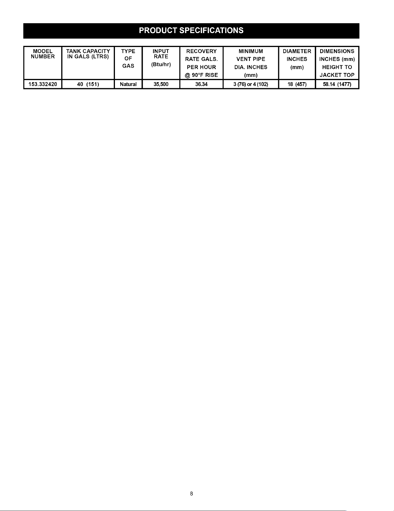
PRODUCT
SPECIFICATIONS
MODEL
|
TANK
CAPACITY
|
TYPE
INPUT
RECOVERY
MINIMUM
DIAMETER
|
DIMENSIONS
NUMBER
|
IN
GALS
(LTRS)
OF
RATE
RATE
GALS.
VENT
PIPE
INCHES
|
INCHES
(mm)
GAS
(Btu/hr)
PER
HOUR
DIA.
INCHES
(mm)
HEIGHT
TO
@
90°F
RISE
(mm)
JACKET
TOP
153.332420
40
(151)
Natural
35,500
36.34
3
(76)
or
4
(102)
18
(457)
58.14
(1477)
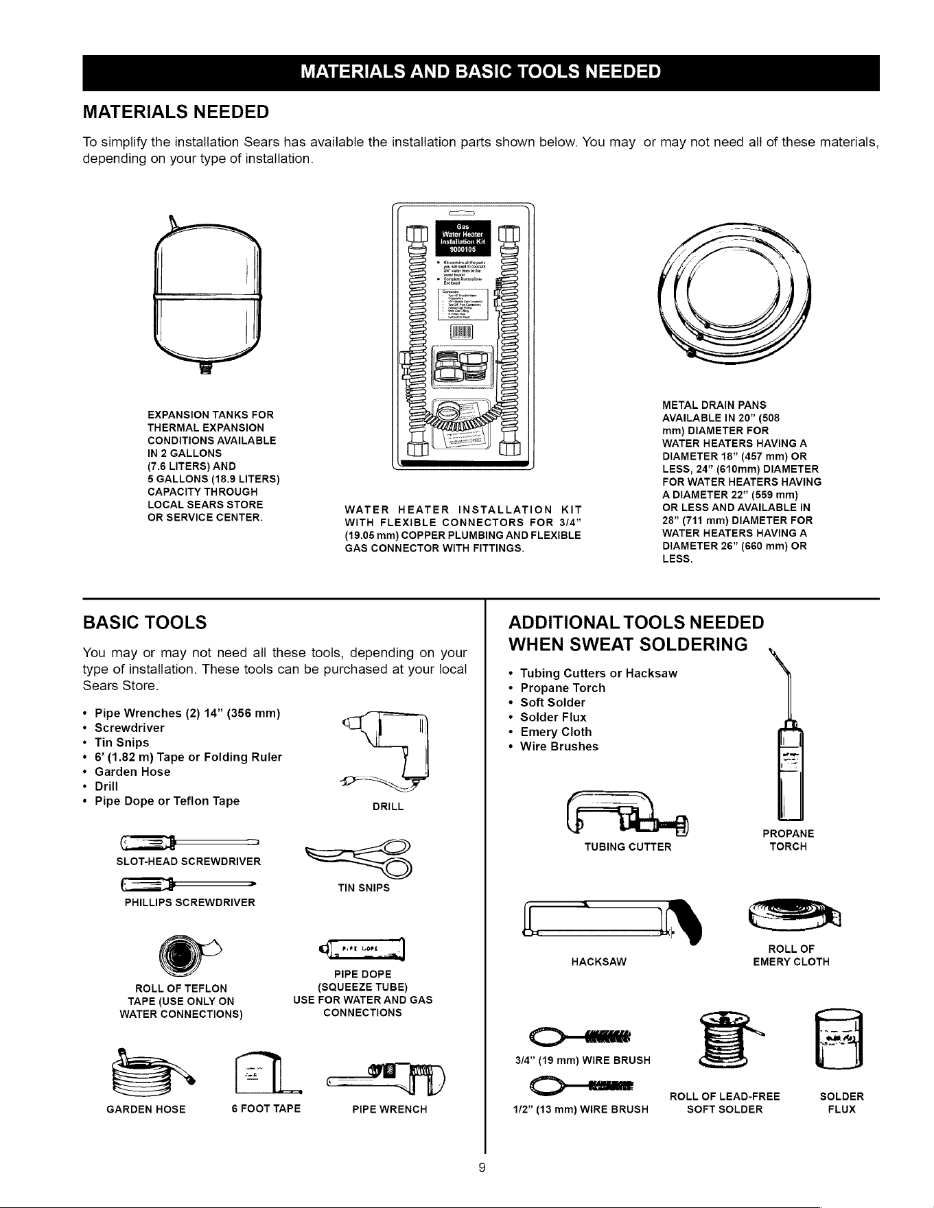
MATERIALS
AND
BASIC
TOOLS
NEEDED
MATERIALS
NEEDED
To
simplify
the
installation
Sears
has
available
the
installation
parts
shown
below.
You
may
or
may
not
need
all
of
these
materials,
depending
on
your
type
of
installation.
eS
Gas
Rema
cog
Mir
Bs
ed
Kit
contin
al
the
parts
you
will
need
to
connect
ia"
water
fies
tothe
Ci
HOOT
TIONING
‘water
beater
Complete
besttactions
Enclosed
{
1
\
EXPANSION
TANKS
FOR
THERMAL
EXPANSION
CONDITIONS
AVAILABLE
IN
2
GALLONS
(7.6
LITERS)
AND
5
GALLONS
(18.9
LITERS)
CAPACITY
THROUGH
LOCAL
SEARS
STORE
METAL
DRAIN
PANS
AVAILABLE
IN
20”
(508
mm)
DIAMETER
FOR
WATER
HEATERS
HAVING
A
DIAMETER
18”
(457
mm)
OR
LESS,
24”
(610mm)
DIAMETER
FOR
WATER
HEATERS
HAVING
A
DIAMETER
22” (559
mm)
WATER
HEATER
INSTALLATION
KIT
OR
LESS
AND
AVAILABLE
IN
OR
SERVICE
CENTER.
WITH
FLEXIBLE
CONNECTORS
FOR
3/4”
28”
(711
mm)
DIAMETER
FOR
(19.05
mm)
COPPER
PLUMBING
AND
FLEXIBLE
WATER
HEATERS
HAVING
A
GAS
CONNECTOR
WITH
FITTINGS.
DIAMETER
26” (660
mm)
OR
LESS.
BASIC
TOOLS
You
may
or
may
not
need
all
these
tools,
depending
on
your
type
of
installation.
These
tools
can
be
purchased
at
your
local
Sears
Store.
¢
Pipe
Wrenches
(2)
14”
(356
mm)
¢
Screwdriver
¢
Tin
Snips
¢
6’
(1.82
m)
Tape
or
Foiding
Ruler
¢«
Garden
Hose
¢
Drill
¢
Pipe
Dope
or
Teflon
Tape
CD
SLOT-HEAD
SCREWDRIVER
cS
TIN
SNIPS
PHILLIPS
SCREWDRIVER
GC
=
PIPE
DOPE
ROLL
OF
TEFLON
(SQUEEZE
TUBE)
TAPE
(USE
ONLY
ON
USE
FOR
WATER
AND
GAS
WATER
CONNECTIONS)
CONNECTIONS
LL.
CWE
aD
—
SE
|
GARDEN
HOSE
6
FOOT
TAPE
PIPE
WRENCH
ADDITIONAL
TOOLS
NEEDED
WHEN
SWEAT
SOLDERING
¢
Tubing
Cutters
or
Hacksaw
¢«
Propane
Torch
¢
Soft
Solder
¢
Solder
Flux
¢
Emery
Cloth
¢
Wire
Brushes
PROPANE
TUBING
CUTTER
TORCH
en
Tne?)
a
D
ROLL
OF
HACKSAW
EMERY
CLOTH
CE
3/4”
(19
mm)
WIRE
BRUSH
=
,
ROLL
OF
LEAD-FREE
SOLDER
1/2”
(13
mm)
WIRE
BRUSH
SOFT
SOLDER
FLUX
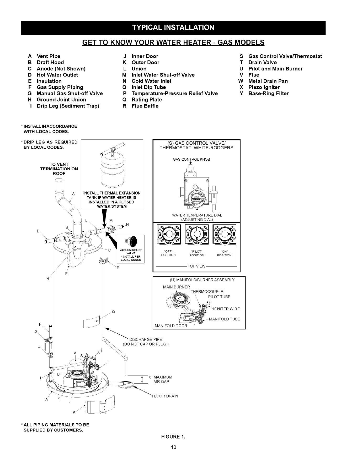
TYPICAL
INSTALLATION
GET
TO
KNOW
YOUR
WATER
HEATER
-
GAS
MODELS
A
Vent
Pipe
J
Inner
Door
S$
Gas
Control
Valve/Thermostat
B
Draft
Hood
K
Outer
Door
T
Drain
Valve
C
Anode
(Not
Shown)
L
Union
U_
Pilot
and Main
Burner
D
Hot
Water
Outlet
M_
Inlet
Water
Shut-off
Valve
Vv
Flue
E
Insulation
N
Cold
Water
Inlet
W
Metal Drain
Pan
F
Gas
Supply
Piping
O
Inlet
Dip
Tube
X
Piezo
Igniter
G
Manual
Gas
Shut-off
Valve
P
Temperature-Pressure
Relief
Valve
Y
Base-Ring
Filter
H_
Ground
Joint
Union
Q_
Rating
Plate
|
Drip
Leg
(Sediment
Trap)
R_
Flue
Baffle
*
INSTALL
INACCORDANCE
WITH
LOCAL
CODES.
“DRIP
LEG
AS
REQUIRED
(S)
GAS
CONTROL
VALVE/
BY
LOCAL
CODES.
THERMOSTAT:
WHITE-RODGERS
GAS
CONTROL
KNOB
TO
VENT
TERMINATION
ON
ROOF
TANK
IF
WATER
HEATER
IS
INSTALLED
IN
A
CLOSED
WATER
SYSTEM
WATER
TEMPERATURE
DIAL
{ADJUSTING
DIAL)
VACUUM
RELIEF
“NOTA
PER
POSITION
POSITION
POSITION
LOCAL
CODES
1
TOP
VIEW
E
R
(U)
MANIFOLD/BURNER
ASSEMBLY
MAIN
BURNER
THERMOCOUPLE
PILOT
TUBE
ja
MANIFOLD
DOOR——
DISCHARGE
PIPE
(DO
NOT
CAP
OR
PLUG.)
6”
MAXIMUM
AIR
GAP
FLOOR
DRAIN
*
ALL
PIPING
MATERIALS
TO
BE
SUPPLIED
BY
CUSTOMERS.
FIGURE
1.
10
IMPORTANT
INFORMATION
ABOUT
THIS
WATER
HEATER
This
gas
water
heater
was
manufactured
to
voluntary
safety
standards
to
reduce
the
likelihood
of
a
flammable
vapor
ignition
incident.
The
new
technology
used
in
meeting
these
standards
makes
this
product
more
sensitive
to
installation
errors.
Please
review
the
following
checklist
and
make
any
required
installation
upgrades
or
changes.
Questions?
Contact
Sears
at
1-800-4-MY-HOME
(1-800-469-4663).
Installation
Checklist
Water
Heater
Location
Water
heater
location
is
important
and
can
affect
system
performance.
Please
check
the
following:
0
sInstallation
area
free
of
corrosive
elements
and
flammable
materials.
O
Centrally
located
with
the
water
piping
system
(For
new
installations).
Located
as
close
to
the
gas
piping
and
vent
pipe
system
as
possible.
O_
Located
indoors
and
in
a
vertical
position.
Protected
from
freezing
temperatures.
O
Proper
clearances
from
combustible
surfaces
maintained
and
not
installed
directly
on
a
carpeted
floor.
O_
Provisions
made
to
protect
the
area
from
water
damage.
Metal
drain
pan
installed
and piped
to
an
adequate
drain.
1
Sufficient
room
to
service
the
water
heater.
See
Clearances
and
Accessibility
section
of
this
manual.
O
Water
heater
not
located
near
an
air
moving
device.
O_sIs
the
installed
environment
dirty
(excessive
amounts
of
lint,
dirt,
dust,
etc.)?
If
so,
the
base-ring
filter
located
on
the
bottom
of
the
water
heater
will
need
to
be
cleaned
periodically.
Refer
to
the
“Maintenance
of
your
Water
Heater”
section
of
this
manual
for
information
on
cleaning
the
base-ring
filter.
Combustion
Air
Supply
and
Ventilation
Check
for
sufficient
combustion
air
supply.
Insufficient
air
for
the
combustion
of
gas
will
result
in
the
flame
becoming
“lazy”,
thereby
allowing
heat
to
build
up
in
the
combustion
chamber.
This
excessive
heat
will
cause
a
thermal
switch
on
the
door
assembly
to trip.
Is
the
water
heater
installed
in
a
closet
or
other
small,
enclosed
space?
If
so:
O
Are
there
openings
for
make-up
air
to
enter
and
exit
the
room/area?
O
Are
the
openings
of
sufficient
size?
Remember,
if
there
are
other
gas-fired
or
air-consuming
appliances
in
the
same
room,
you
need
more
make-up
air.
Refer
to
the
“Installation
Instructions”
and
“Combustion
Air
Supply
and
Ventilation”
sections
for
specific
requirements.
Make
sure
that
fresh
air
is
not
taken
from
areas
that
contain
negative
pressure
producing
devices
such
as
exhaust
fans,
dryers,
fireplaces,
etc.
Is
there
a
furnace/air
handler
in
the
same
room
space
as
the
water
heater?
If
so,
has
a
return
air
duct
system
been
attached
that
exits
the
room?
If
so,
check
for
leaks
on
the
air
duct
system.
If
no
air
duct
system
is
present,
correct
immediately
by
contacting
a
local
Heating,
Ventilation,
Air-
Conditioning
&
Refrigeration
(HVAC-R)
authorized
service
provider.
Use
a
fresh
air
supply
that
is
free
of
corrosive
elements
and
flammable
vapors.
11
O_
Fresh
air
openings
must
be
sized
correctly
with
consideration
given
to
the
blocking
effect
of
louvers
and
grilles.
4
Ductwork
must
be
the
same
cross-sectional
area
as
the
openings.
Vent
Pipe
System
Check
for
proper
drafting
at
the
water
heater
draft
hood.
Refer
to
the
“Checking
the
Draft”
section
of
this
manual
for
the
test
procedure.
If
the
procedure
shows
insufficient
draft
is
present,
please
check
the
following:
O
Draft
hood
properly
installed.
O
Vent
connectors
securely
fastened
with
screws
and
supported
properly
to
maintain
six
inch
clearance.
O
Vent
connector
made
of
approved
material
and
sized
correctly.
O_
Vent
pipe
system
installed
according
to
all
local
and
state
codes
or,
in
the
absence
of
local
and
state
codes,
the
“National
Fuel
Gas
Code”,
ANSI
Z223.1(NFPA
54)-current
edition.
O_
Flue
baffle
properly
positioned
in
the
flue
tube.
O
Check
the
vent
system
for
restrictions/obstructions
and
check
the
vent
termination
height.
Refer
to
the
“Combustion
Air
Supply
and
Ventilation”
section
of
this
water
heater
manual
for
specific
requirements.
O
Recheck
for
sufficient
combustion
air
supply.
Water
System
Piping
O_
Temperature
and
pressure
relief
valve
properly
installed
with
a
discharge
line
run
to
an
open
drain
and
protected
from
freezing.
Ail
piping
properly
installed
and
free
of
leaks.
Heater
completely
filled
with
water.
Closed
system
pressure
build-up
devices
installed.
Ooo
0
Mixing
valve
(when
applicable)
installed
per
manufacturer's
instructions
(See
“Water
Temperature
Regulation”
section).
Gas
Supply
and
Piping
O_
Gas
type
is
the
same
as
that
listed
on
the
water
heater
rating
plate.
O_
Gas
line
equipped
with
shut-off
valve,
union,
and
drip
leg.
O_
Use
pipe
joint
compound
or
teflon
tape
marked
as
being
resistant
to
the
action
of
petroleum
[Propane
(L.P.)]
gases.
O
Adequate
pipe
size
and
approved
pipe material.
O
An
approved
noncorrosive
leak
detection
solution
used
to
check
all
connections
and
fittings
for
possible
gas
leaks.
Correct
any
leak
found.
INSTALLATION
INSTRUCTIONS
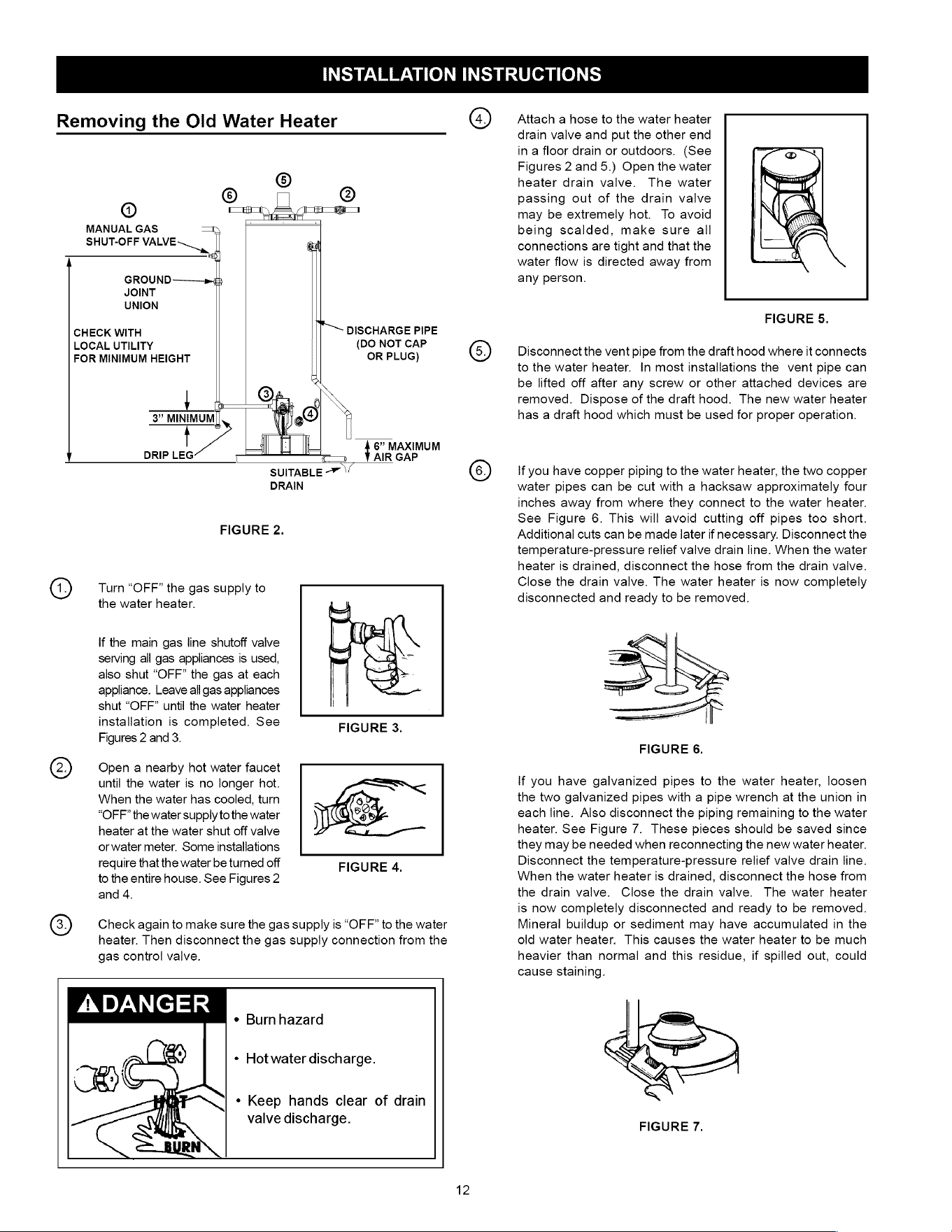
Removing
the
Old
Water
Heater
SHUT-OFF
VALVE
MANUAL
GAS
GROUND
JOINT
UNION
CHECK
WITH
LOCAL
UTILITY
FOR
MINIMUM
HEIGHT
o_o
(DO
NOT
CAP
OR
PLUG)
3”
MINIMUM
”
|
6”
MAXIMUM
DRIP
LEG
c
c=
AIR
GAP
SUITABLE
-”
DRAIN
FIGURE
2.
t~
DISCHARGE
PIPE
Turn
“OFF”
the
gas
supply
to
the
water
heater.
If
the
main
gas
line
shutoff
valve
serving
all
gas
appliances
is
used,
also
shut
“OFF”
the
gas
at
each
appliance.
Leave
all
gas
appliances
shut
“OFF”
until
the
water
heater
installation
is
completed.
See
Figures
2
and
3.
Open
a
nearby
hot
water
faucet
until
the
water
is
no
longer
hot.
When
the
water
has cooled,
turn
“OFF”
the
water
supply
to
the
water
heater
at
the
water
shut
off
valve
orwater
meter.
Some
installations
require
that
the
water
be
turned
off
to
the
entire
house.
See
Figures
2
and
4.
FIGURE
4.
Check
again
to
make
sure
the
gas
supply
is
“OFF”
to
the
water
heater.
Then
disconnect
the
gas
supply
connection
from
the
gas
control
valve.
ADANGER
¢«
Burnhazard
«
Hot
water
discharge.
*
Keep
hands
clear
of
drain
valve
discharge.
12
©
Attach
a
hose
to
the
water
heater
drain
valve
and
put the
other
end
in
a
floor
drain
or
outdoors.
(See
Figures
2
and
5.)
Open
the
water
heater
drain
valve.
The
water
passing
out
of
the
drain
valve
may
be
extremely
hot.
To
avoid
being
scalded,
make
sure
all
connections
are
tight
and
that
the
water
flow
is
directed
away
from
any
person.
FIGURE
5.
Disconnect
the
vent
pipe
from
the
draft
hood
where
it
connects
to
the
water
heater.
In
most
installations
the
vent
pipe
can
be
lifted
off
after
any
screw
or
other
attached
devices
are
removed.
Dispose
of
the draft
hood.
The
new
water
heater
has
a
draft
hood
which
must
be
used
for
proper
operation.
If
you
have
copper
piping
to
the
water
heater,
the
two
copper
water
pipes
can
be
cut
with
a
hacksaw
approximately
four
inches
away
from
where
they
connect
to
the
water
heater.
See
Figure
6.
This
will
avoid
cutting
off
pipes
too
short.
Additional
cuts
can
be
made
later
if
necessary.
Disconnect
the
temperature-pressure
relief
valve
drain
line.
When
the
water
heater
is
drained,
disconnect
the
hose
from
the
drain
valve.
Close
the
drain
valve.
The
water
heater
is
now
completely
disconnected
and
ready
to
be
removed.
FIGURE
6.
If
you
have
galvanized
pipes
to
the
water
heater,
loosen
the
two
galvanized
pipes
with
a
pipe
wrench
at
the
union
in
each
line.
Also
disconnect
the
piping
remaining
to
the
water
heater.
See
Figure
7.
These
pieces
should
be
saved
since
they
may
be
needed when
reconnecting
the
new
water
heater.
Disconnect
the
temperature-pressure
relief
valve
drain
line.
When
the
water
heater
is
drained,
disconnect
the
hose
from
the
drain
valve.
Close
the
drain
valve.
The water
heater
is
now
completely
disconnected
and
ready
to
be
removed.
Mineral buildup
or
sediment
may
have
accumulated
in
the
old
water
heater.
This
causes
the
water
heater
to
be
much
heavier
than
normal
and
this
residue,
if
spilled
out,
could
cause
staining.
FIGURE
7.
Location
Requirements
A
WARNING
Carbon
Monoxide
Poisoning
Hazard
Do
not
install
in
a
mobile
home.
Doing
so
can
result
in
carbon
monoxide
poisoning
and
death.
The
FVIR
System
is
designed
to
reduce
the
risk
of
flammable
vapor-related
fires.
The
patented
system
protects
your
family
by
trapping
the
burning
vapors
within
the
water
heater
combustion
chamber
through
the
special
flame-arrestor.
The
burning
vapors
literally
“burn
themselves
out”
without
escaping
back
into
the
room.
In
the
event
of
a
flammable
vapor
incident,
the
FVIR
System
disables
the
water
heater
by
shutting
off
the
gas
supply
to
the
water
heater’s
burner
and
pilot,
preventing
re-ignition
of
any
remaining
flammable
vapors
in
the
area.
This
will
not
prevent
a
possible
fire/explosion
if
the
igniter
is
depressed
and
flammable
vapors
have
accumulated
in
the
combustion
chamber
with
the
pilot light
off.
If
you
suspect
a
flammable
vapor
incident
has
occurred,
do
not
use
this
appliance.
Do
not
attempt
to
light
this
appliance,
or
depress
the
igniter
button
if
you
suspect
flammable
vapors
have
accumulated
inside
or
outside
the
appliance.
Immediately
call
a
qualified
technician
to
inspect
the
appliance.
Water
heaters
subjected
to
a
flammable
vapors
incident
will
show
a
discoloration
on
the
flame-arrestor
and
require
replacement
of
the
entire
water
heater.
AWARNING
Flammable
Vapors
FIRE
AND
EXPLOSION
HAZARD
Can
result
in
serious
injury
or
death
A
Do
not
store
or
use
gasoline
or
other
flammable
vapors
and
liquids
in
the
vicinity
of
this
or
any
other
appliance.
Storage
of
or
use
of
gasoline
or
other
flammable
vapors
or
liquids
in
the
vicinity
of
this
or
any
other
appliance
can
result
in
serious
injury
or
death.
Read
and
follow
water
heater
warnings
and
instructions.
Do
not
use
or
store
flammable
products
such
as
gasoline,
solvents,
or
adhesives
in
the
same
room
or
area
near
the
water
heater.
If
such
flammables
must
be
used,
all
gas
burning
appliances
in
the
vicinity
must
be
shut
off
and
their
pilot
lights
extinguished.
Open
the
doors
and
windows
for
ventilation
while
flammable
substances
are
in
use.
lf
flammable
liquids
or
vapors
have
spilled
or
leaked
in
the
area
of
the
water
heater,
leave
the
area
immediately
and
call
the
fire
department
from
a
neighbor's
home.
Do
not
attempt
to
clean
the
spill
until
all
ignition
sources
have
been
extinguished.
A
WARNING
Fire
or
Explosion
Hazard
¢
Read
instruction
manual
before
installing,
using
or
servicing
water
heater.
¢
Improper
use
may
result
in
fire
or
explosion.
¢
Maintain
required
clearances
to
combustibles.
Keep
combustibles
such
as
boxes,
magazines,
clothes,
etc.
away
from
the
water
heater
area.
Site
Location
«
Select
a
location
near
the
center
of
the
water
piping
system.
The water
heater
must
be
installed
indoors
and
in
a
vertical
position
on
a
level
surface.
DO
NOT
install
in
bathrooms,
bedrooms,
or
any
occupied
room
normally
kept
closed.
«
Locate
the
water
heater
as
close
to
the
chimney
or
gas
vent
as
practical.
Consider
the
vent
system
piping
and
combustion
air
supply
requirements
when
selecting
the
water
heater
location.
The
venting
system
must
be
able
to
run
from
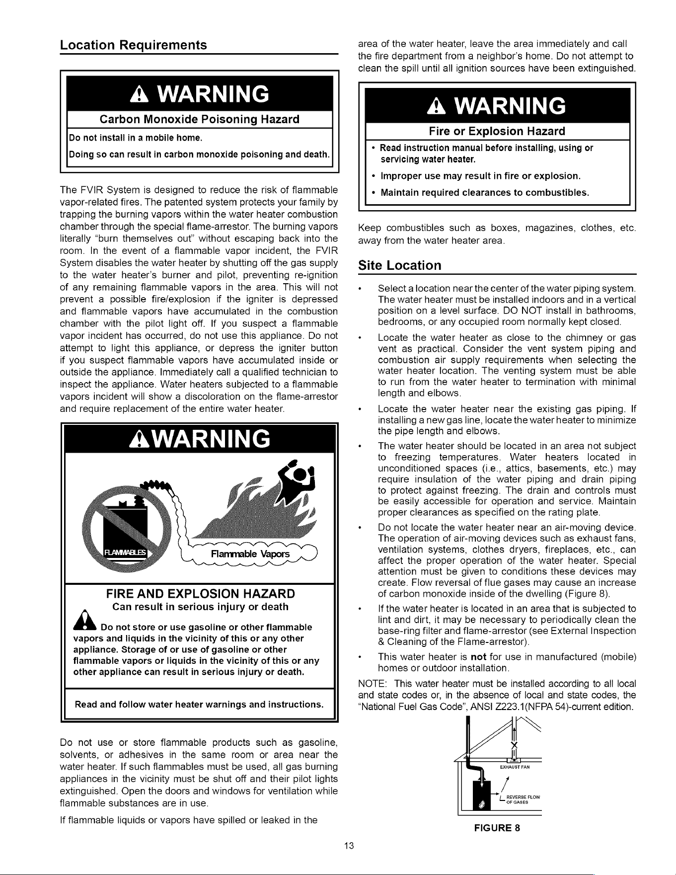
the
water
heater
to
termination
with
minimal
length
and
elbows.
«
Locate
the
water
heater near
the
existing
gas
piping.
If
installing
a
new
gas
line,
locate
the
water
heater
to
minimize
the
pipe
length
and
elbows.
«
The
water
heater
should
be
located
in
an
area
not
subject
to
freezing
temperatures.
Water
heaters
located
in
unconditioned
spaces
(i.e.,
attics,
basements,
etc.)
may
require
insulation
of
the
water
piping
and
drain
piping
to
protect
against
freezing.
The
drain
and
controls
must
be
easily
accessible
for
operation
and
service.
Maintain
proper
clearances
as
specified
on
the
rating
plate.
*
Do
not
locate
the
water
heater
near
an
air-moving
device.
The operation
of
air-moving
devices
such
as
exhaust
fans,
ventilation
systems,
clothes
dryers,
fireplaces,
etc.,
can
affect
the
proper
operation
of
the
water
heater.
Special
attention
must
be
given
to
conditions
these
devices
may
create.
Flow
reversal
of
flue
gases
may
cause
an
increase
of
carbon
monoxide
inside
of
the
dwelling
(Figure
8).
«
—
If
the
water
heater
is
located
in
an
area
that
is
subjected
to
lint
and
dirt,
it
may
be
necessary
to
periodically
clean
the
base-ring
filter
and
flame-arrestor
(see
External
Inspection
&
Cleaning
of
the
Flame-arrestor).
«
This
water
heater
is
not
for
use
in
manufactured
(mobile)
homes
or
outdoor
installation.
NOTE:
This
water
heater
must
be
installed
according
to
all
local
and
state
codes
or,
in
the
absence
of
local
and
state
codes,
the
“National
Fuel
Gas
Code”,
ANS]
Z223.1(NFPA
54)-current
edition.
EXHAUST
FAN
}
L_
REVERSE
FLOW
F
GASES
FIGURE
8
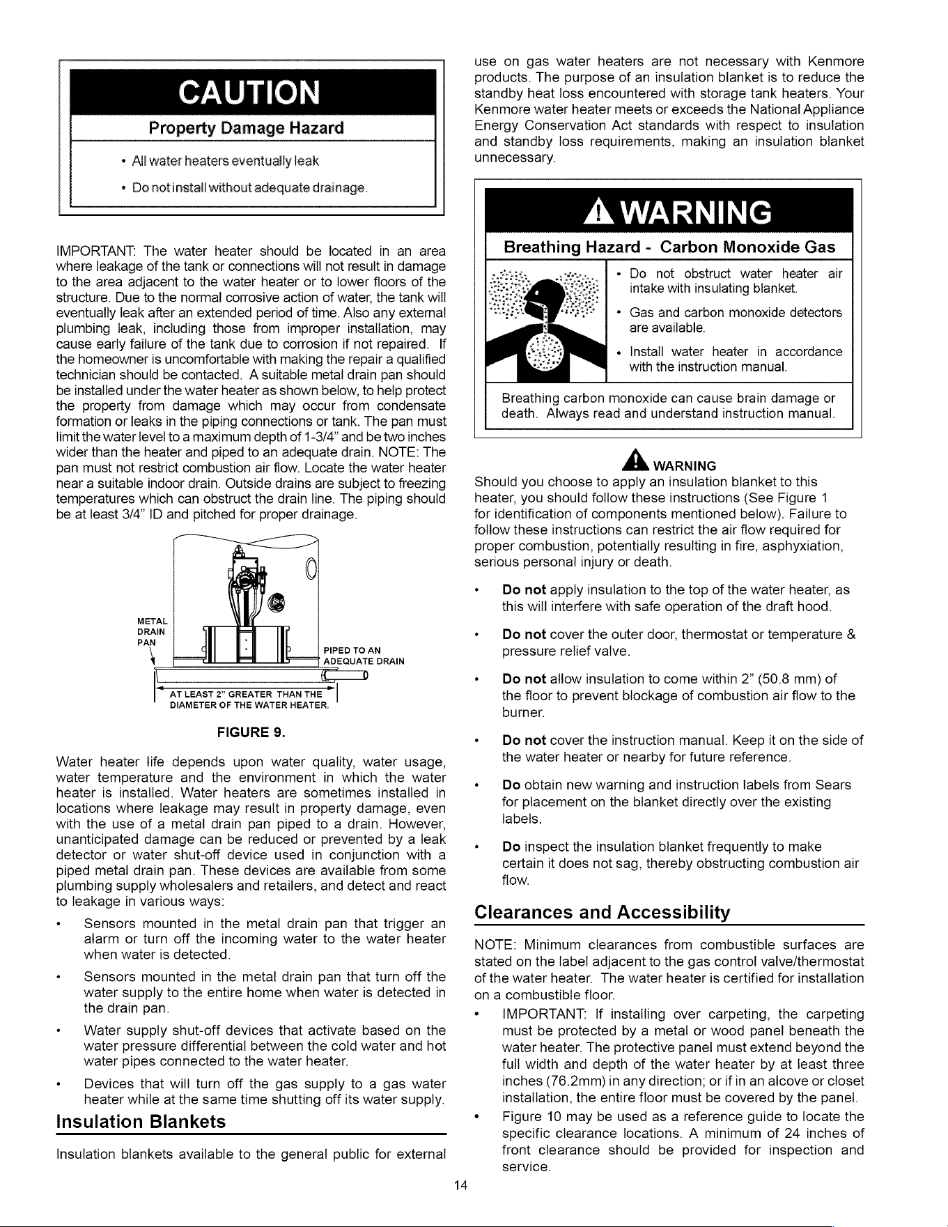
CAUTION
Property
Damage
Hazard
»
All
water
heaters
eventually
leak
«
Do
notinstall
without
adequate
drainage.
IMPORTANT.
The
water
heater
should
be
located
in
an
area
where
leakage
of
the
tank
or
connections
will
not
result
in
damage
to
the
area
adjacent
to
the
water
heater
or
to
lower
floors
of
the
structure.
Due
to
the
normal
corrosive
action
of
water,
the
tank
will
eventually
leak
after
an
extended
period
of
time.
Also
any
external
plumbing
leak,
including
those
from
improper
installation,
may
cause
early
failure
of
the
tank
due
to
corrosion
if
not
repaired.
If
the
homeowner
is
uncomfortable
with
making
the
repair
a
qualified
technician
should
be
contacted.
A
suitable
metal
drain
pan
should
be
installed
under
the
water
heater
as
shown
below,
to
help
protect
the
property
from
damage
which
may
occur
from
condensate
formation
or
leaks
in
the
piping
connections
or
tank.
The
pan
must
limit
the
water
level
to
a
maximum
depth
of
1-3/4”
and
be
two
inches
wider
than
the
heater
and piped
to
an
adequate
drain.
NOTE:
The
pan
must
not
restrict
combustion
air
flow.
Locate
the
water
heater
near
a
suitable
indoor
drain.
Outside
drains
are
subject
to
freezing
temperatures
which
can
obstruct
the
drain
line.
The
piping
should
be
at
least
3/4”
ID
and
pitched
for
proper
drainage.
0
|
|
PIPED
TO
AN
| |
ADEQUATE
DRAIN
AT
LEAST
2”
GREATER
THAN
THE
DIAMETER
OF
THE
WATER
HEATER.
6
METAL
DRAIN
PAN
FIGURE
9.
Water
heater
life
depends
upon
water
quality,
water
usage,
water
temperature
and
the
environment
in
which
the
water
heater
is
installed.
Water
heaters
are
sometimes
installed
in
locations
where
leakage
may
result
in
property
damage,
even
with
the
use
of
a
metal
drain
pan
piped
to
a
drain.
However,
unanticipated
damage
can
be
reduced
or
prevented
by
a
leak
detector
or
water
shut-off
device
used
in
conjunction
with
a
piped metal
drain
pan.
These
devices
are
available
from
some
plumbing
supply
wholesalers
and
retailers,
and
detect
and
react
to
leakage
in
various
ways:
«
Sensors
mounted
in
the
metal
drain
pan
that
trigger
an
alarm
or
turn
off
the
incoming
water
to
the
water
heater
when
water
is
detected.
«
Sensors
mounted
in
the
metal
drain
pan
that turn
off
the
water
supply
to
the
entire
home
when
water
is
detected
in
the
drain
pan.
«
Water
supply
shut-off
devices
that
activate
based
on
the
water
pressure
differential
between
the
cold
water
and
hot
water
pipes
connected
to
the
water
heater.
«
Devices
that
will
turn
off
the
gas
supply
to
a
gas
water
heater
while
at
the
same
time
shutting
off
its
water
supply.
Insulation
Blankets
Insulation
blankets
available
to
the
general
public
for
external
14
use
on
gas
water
heaters
are
not
necessary
with
Kenmore
products.
The
purpose
of
an
insulation
blanket
is
to
reduce
the
standby
heat
loss
encountered
with
storage
tank
heaters.
Your
Kenmore
water
heater
meets
or
exceeds
the
National
Appliance
Energy
Conservation
Act
standards
with
respect
to
insulation
and
standby
loss
requirements,
making
an
insulation
blanket
unnecessary.
A
WARNING
Breathing
Hazard
-
Carbon
Monoxide
Gas
+
Do
not
obstruct
water
heater
air
intake
with
insulating
blanket.
*
Gas
and
carbon
monoxide
detectors
are
available.
+
Install
water
heater
in
accordance
with
the
instruction
manual.
Breathing
carbon
monoxide
can
cause
brain
damage
or
death.
Always
read
and
understand
instruction
manual.
A
WARNING
Should
you
choose
to
apply
an
insulation
blanket
to
this
heater,
you
should
follow
these
instructions
(See
Figure
1
for
identification
of
components
mentioned
below).
Failure
to
follow
these
instructions
can
restrict
the
air
flow
required
for
proper
combustion,
potentially
resulting
in
fire,
asphyxiation,
serious
personal
injury
or
death.
«
Do
not
apply
insulation
to
the
top
of
the
water
heater,
as
this
will
interfere
with
safe
operation
of
the
draft
hood.
«
Do
not
cover
the
outer
door,
thermostat
or
temperature
&
pressure
relief
valve.
*
Deo
not
allow
insulation
to
come
within
2”
(50.8
mm)
of
the
floor
to
prevent
blockage
of
combustion
air
flow
to
the
burner.
«
Do
not
cover
the
instruction
manual.
Keep
it
on
the
side
of
the
water
heater
or
nearby
for
future
reference.
«
Do
obtain
new
warning
and
insiruction
labels
from
Sears
for
placement
on
the
blanket
directly
over
the
existing
labels.
«
Do
inspect
the
insulation
blanket
frequently
to
make
certain
it
does
not
sag,
thereby
obstructing
combustion
air
flow.
Clearances
and
Accessibility
NOTE:
Minimum
clearances
from
combustible
surfaces
are
stated
on
the
label
adjacent
to
the
gas
control
vailve/thermostat
of
the
water
heater.
The
water
heater
is
certified
for
installation
on
a
combustible
floor.
*
IMPORTANT:
If
installing
over
carpeting,
the
carpeting
must
be
protected
by
a
metal
or
wood
panel
beneath
the
water
heater.
The
protective
panel
must
extend
beyond
the
full
width and
depth
of
the
water
heater
by
at
least
three
inches
(76.2mm)
in
any
direction;
or
if
in
an
alcove
or
closet
installation,
the
entire
floor
must
be
covered
by
the
panel.
*
Figure
10
may
be
used
as
a
reference
guide
to
locate
the
specific
clearance
locations.
A
minimum
of
24
inches
of
front
clearance
should
be
provided
for
inspection
and
service.
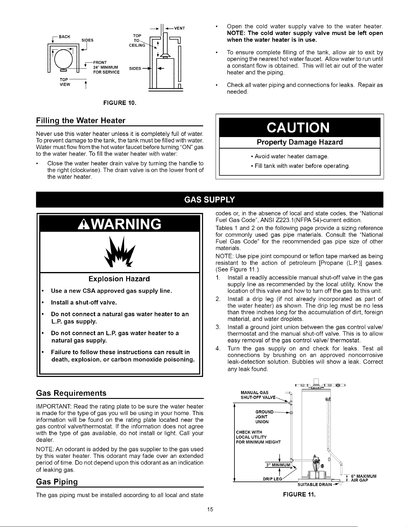
—_
| |
<—
VENT
BACK
TOP
L
SIDES
To
=]
CEILING
y
;
FRONT
24”
MINIMUM
SIDES
<4
FOR
SERVICE
TOP
VIEW
n
FIGURE
10.
Filling
the
Water
Heater
Never
use
this
water
heater
unless
it
is
completely
full
of
water.
To
prevent
damage
to
the
tank,
the
tank
must
be
filled
with
water.
Water
must
flow
from
the
hot
water
faucet
before
turning
“ON”
gas
to
the
water
heater.
To
fill
the
water
heater
with
water:
*«
Close
the
water
heater
drain
valve
by
turning
the
handle
to
the
right
(clockwise).
The
drain
valve
is
on
the
lower
front
of
the
water
heater.
*
Open
the
cold
water supply
valve
to
the
water
heater.
NOTE:
The
cold
water
supply
valve
must
be
left
open
when
the
water
heater
is
in
use.
«
To
ensure
complete
filling
of
the
tank,
allow
air to
exit
by
opening
the
nearest
hot
water
faucet.
Allow
water
to
run
until
a
constant
flow
is
obtained.
This
will
let
air
out
of
the
water
heater
and
the
piping.
«
Check
all
water
piping
and
connections
for
leaks.
Repair
as
needed.
CAUTION
Property
Damage
Hazard
¢
Avoid
water
heater
damage.
¢
Fill
tank
with
water
before
operating.
GAS
SUPPLY
AWARNING
Explosion
Hazard
«
Use
anew
CSA
approved
gas
supply
line.
*
Install
a
shut-off
valve.
*
Do
not
connect
a
natural
gas
water
heater
to
an
L.P.
gas
supply.
«
Do
not
connect
an
L.P.
gas
water
heater
to
a
natural
gas
supply.
¢
Failure
to
follow
these
instructions
can
result
in
death,
explosion,
or
carbon
monoxide
poisoning.
Gas
Requirements
IMPORTANT:
Read
the
rating
plate
to
be
sure
the
water
heater
is
made
for
the
type
of
gas
you
will
be
using
in
your
home.
This
information
will
be
found
on
the
rating
plate
located
near
the
gas
control
valve/thermosiat.
If
the
information
does
not
agree
with
the
type
of
gas
available,
do
not
install
or
light.
Call
your
dealer.
NOTE:
An
odorant
is
added
by
the
gas
supplier
to
the
gas
used
by
this
water
heater.
This
odorant
may
fade
over
an
extended
period
of
time.
Do
not
depend
upon
this
odorant
as
an
indication
of
leaking
gas.
Gas
Piping
The
gas
piping
must
be
installed
according
to
all
local
and
state
15
codes
or,
in
the
absence
of
local
and
state
codes,
the
“National
Fuel
Gas
Code”,
ANSI
Z223.1(NFPA
54)-current
edition.
Tables
1
and
2
on
the
following
page
provide
a
sizing
reference
for
commonly
used
gas
pipe
materials.
Consult
the
“National
Fuel
Gas
Code”
for
the
recommended
gas
pipe
size
of
other
materials.
NOTE:
Use
pipe
joint
compound
or
teflon
tape
marked
as
being
resistant
to
the
action
of
petroleum
[Propane
(L.P.)]
gases.
(See
Figure
11.)
1.
Install
a
readily
accessible
manual
shut-off
valve
in
the
gas
supply
line
as
recommended
by
the
local
utility.
Know
the
location
of
this
valve
and
how
to
turn
off
the
gas
to
this
unit.
2.
Install
a
drip
leg
(if
not
already
incorporated
as
part
of
the
water
heater)
as
shown.
The
drip
leg
must
be
no
less
than
three
inches
long
for
the
accumulation
of
dirt,
foreign
material,
and
water
droplets.
3.
Install
a
ground
joint
union
between
the
gas
control
valve/
thermostat
and
the
manual
shut-off
valve.
This
is
to
allow
easy
removal
of
the
gas
control
valve/
thermostat.
4.
Turn
the
gas
supply
on
and
check
for
leaks.
Test
all
connections
by
brushing
on
an
approved
noncorrosive
leak-detection
solution.
Bubbles
will
show
a
leak.
Correct
any
leak
found.
MANUAL
GAS
SHUT-OFF
VALVE
ae.
GROUND
JOINT
UNION
CHECK
WITH
LOCAL
UTILITY
FOR
MINIMUM
HEIGHT
3”
MINIMUM
DRIP
17
=
SUITABLE
DRAIN -*/
FIGURE
11.
~
#6”
MAXIMUM
AIR
GAP
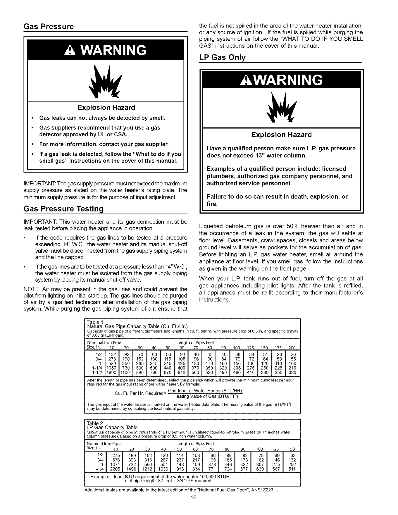
Gas
Pressure
A
WARNING
Explosion
Hazard
Gas
leaks
can
not
always
be
detected
by
smell.
Gas
suppliers
recommend
that
you
use
a
gas
detector
approved
by
UL
or
CSA.
For
more
information,
contact
your
gas
supplier.
If
a
gas
leak
is
detected,
follow
the
“What
to
do
if
you
smell
gas”
instructions
on
the
cover
of
this
manual.
IMPORTANT:
The
gas
supply
pressure
must
not
exceed
the
maximum
supply
pressure
as
siated
on
the
water
heater’s
rating
plate.
The
minimum
supply
pressure
is
for
the
purpose
of
input
adjustment.
Gas
Pressure
Testing
the
fuel
is
not
spilled
in
the
area
of
the
water
heater
installation,
or
any
source
of
ignition.
If
the
fuel
is
spilled
while
purging
the
piping
system
of
air
follow
the
“WHAT
TO
DO
IF
YOU
SMELL
GAS”
instructions
on
the
cover
of
this
manual.
LP
Gas
Only
OY
NTT
Explosion
Hazard
Have
a
qualified
person
make
sure
L.P.
gas
pressure
does
not
exceed
13”
water
column.
Examples
of
a
qualified
person
include:
licensed
plumbers,
authorized
gas
company
personnel,
and
authorized
service
personnel.
Failure
to
do
so
can
result
in
death,
explosion,
or
fire.
IMPORTANT.
This
water
heater
and
its
gas
connection
must
be
leak
tested
before
placing
the
appliance
in
operation.
If
the
code
requires
the
gas
lines
to
be
tested
at
a
pressure
exceeding
14”
W.C.,
the
water
heater
and
its
manual
shut-off
vaive
must
be
disconnected
from
the
gas
supply
piping
system
and
the
line
capped.
If
the
gas
lines
are
to
be
tested
at
a
pressure
less
than
14”
W.C.,
the
water
heater
must
be
isolated
from
the
gas
supply
piping
system
by
closing
its
manual
shut-off
valve.
NOTE:
Air
may
be
present
in
the
gas
lines
and
could
prevent
the
pilot
from
lighting
on
initial
start-up.
The
gas
lines
should
be
purged
of
air
by
a
qualified
technician
after
installation
of
the
gas
piping
system.
While
purging
the
gas
piping
system
of
air,
ensure
that
Liquefied
petroleum
gas
is
over
50%
heavier
than
air
and
in
the
occurrence
of
a
leak
in
the
system,
the
gas
will
settle
at
floor
level.
Basements,
crawl
spaces,
closets
and
areas
below
ground
level
will
serve
as
pockets
for
the
accumulation
of
gas.
Before
lighting
an
L.P.
gas
water
heater,
smell
all
around
the
appliance
at
floor
level.
If
you
smell
gas,
follow
the
instructions
as
given
in
the
warning
on
the front
page.
When
your
L.P.
tank runs
out
of
fuel,
turn
off
the
gas
at
all
gas
appliances
including
pilot
lights.
After
the
tank
is
refilled,
all
appliances
must
be
re-lit
according
to
their
manufacturer’s
instructions.
Table
1
: .
Natural
Gas
Pipe
Capacity
Table
(Cu.
Ft./Hr.)
of
0.60
(natural
gas).
Capacity
of
gas
pipe
of
different
diameters
and
lengths
in
cu.
ft.
per
hr.
with
pressure
drop
of
0.3
in.
and
specific
gravity
Nominal
Iron
Pipe
Size,
in.
Length
of
Pipe,
Feet
10
20
30
40 50 60
79 80 Oh
OO
2
nO
ee
ZB
eee
0)
2
|
1382)
92
|
73]
63
56
50)
46) 43) 40)
38)
34
31
28
|
26
3/4
|
278
|
190
|
152
|
130
|
115
|
1057)
967 90] 847
79
72 | 64
59
55
1
|
520
|
350
|
285
|
245
|
215
|
195
|
180
|
170
|
160
|
150
|
130
|
120
|
110
|
100
1-1/4
71050
|
730
|
590
|
500
|
440
|
400
|
370
|
350
|
320
|
305
|
275
|
250
|
225
|
210
4-1/2
1600
71100
|
890
|
760
|
670
|
610
|
560
|
530
|
490
|
460
|
410
|
380
|
350
|
320
Cu.
Ft.
Per
Hr.
Required=
After
the
length
of
pipe
has
been
determined,
select
the
pipe
size
which
will
provide
the
minimum
cubic
feet
per
hour
required
for
the
gas
input
rating
of
the
water
heater.
By
formula:
Gas
Input
of
Water
Heater
(BTU/HR)
Heating
Value
of
Gas
(BTU/FT*)
The
gas
input
of
the
water
heater
is
marked
on
the
water
heater
data
plate.
The
heating
value
of
the
gas
(BTU/FT°)
may
be
determined
by
consulting
the
local
natural
gas
utility.
Table
2
;
LP
Gas
Capacity
Table
Maximum
capacity
of
pipe
in
thousands
of
BTU
per
hour
of
undiluted
liquefied
petroleum
gases
(at
11
inches
water
column
pressure).
Based
on
a
pressure
drop
of
0.5
inch
water
column.
Nominal
lron
Pipe
Length
of
Pipe,
Feet
Size,
in.
10
Q
30
4g
50
60
ZO
80 20
YOO,
al
2S
curecl
30
12
275
189
152 129
114
103
96 89 83 78 69 63
3/4
576) 393) 315) 267)
2374
217
196
185
173
162
146
132
14)
1071
7324 590]
504),
4487)
409)
378) 346)
322)
307)
2754)
252
1-1/4)
2205)
1496) 1212] 1039)
913]
834]
771
724
6774)
630
|
5677)
511
Example:
Input
BTU
requirement
of
the
water
heater
100,000
BTUH.
Total
pipe
length,
80
feet
=
3/4"
IPS
required.
Additional
tables
are
available
in
the
latest
edition
of
the
"National
Fuel
Gas
Code",
ANSI
2223.1.
16
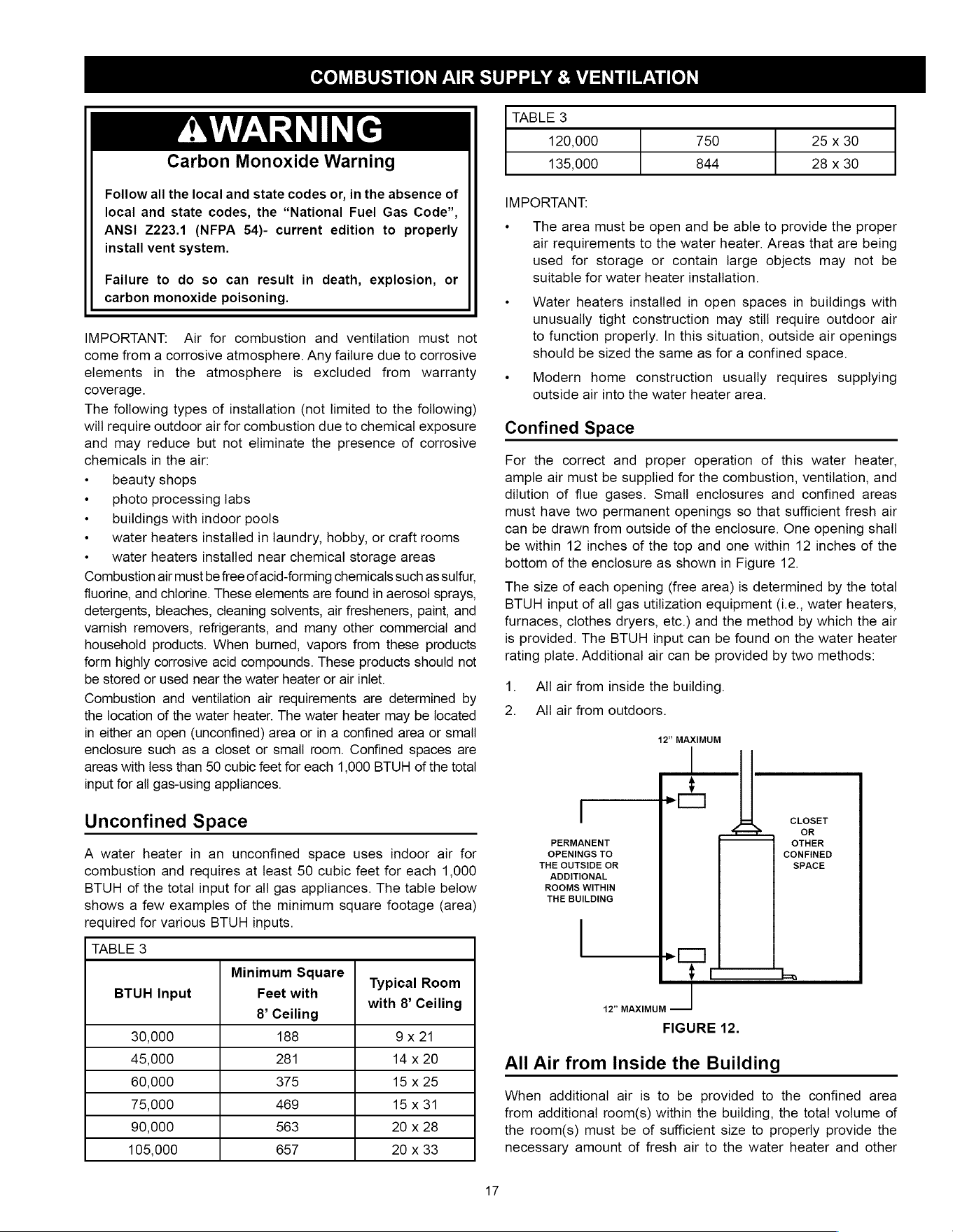
COMBUSTION
AIR
SUPPLY
&
VENTILATION
AWARNING
Carbon
Monoxide
Warning
Follow
all
the
local
and
state
codes
or,
in
the
absence
of
local
and
state
codes,
the
“National
Fuel
Gas
Code”,
ANSI
2223.1
(NFPA
54)-
current
edition
to
properly
install
vent
system.
Failure
to
do
so
can
result
in
death,
explosion,
or
carbon
monoxide
poisoning.
IMPORTANT:
Air
for
combustion
and
ventilation
must
not
come
from
a
corrosive
atmosphere.
Any
failure
due
to
corrosive
elements
in
the
atmosphere
is
excluded
from
warranty
coverage.
The
following
types
of
installation
(not
limited
to
the
following)
will
require
outdoor
air
for
combustion
due
to
chemical
exposure
and
may
reduce
but
not
eliminate
the
presence
of
corrosive
chemicals
in
the
air:
*
beauty
shops
«
photo
processing
labs
*
buildings
with
indoor
pools
*
water
heaters
installed
in
laundry,
hobby,
or
craft
rooms
«
water
heaters
installed
near
chemical
storage
areas
Combustion
air
must
be
free
of
acid-forming
chemicals
such
as
sulfur,
fluorine,
and
chlorine.
These
elements
are
found
in
aerosol
sprays,
detergents,
bleaches,
cleaning
solvents,
air
fresheners,
paint,
and
varnish
removers,
refrigerants,
and
many
other
commercial
and
household
products.
When
burned,
vapors
from
these
products
form
highly
corrosive
acid
compounds.
These
products
should
not
be
stored
or
used
near
the
water
heater
or
air
inlet.
Combustion
and
ventilation
air
requirements
are
determined
by
the
location
of
the
water
heater.
The
water
heater
may
be
located
in
either
an
open
(unconfined)
area
or
in
a
confined
area
or
small
enclosure
such
as
a
closet
or
small
room.
Confined
spaces
are
areas
with
less
than
50
cubic
feet
for
each
1,000
BTUH
of
the
total
input
for
all
gas-using
appliances.
Unconfined
Space
A
water
heater
in
an
unconfined
space
uses
indoor
air
for
combustion
and
requires
at
least 50
cubic
feet
for
each
1,000
BTUH
of
the
total
input
for
all
gas
appliances.
The
table
below
shows
a
few
examples
of
the
minimum
square
footage
(area)
required
for
various
BTUH
inputs.
TABLE
3
Minimum
Square
.
BTUH
Input
Feet
with
Typical
Room
8’
Ceiling
with
8’
Ceiling
30,000
188
9x
21
45,000
281
14
x
20
60,000
375
15
x
25
75,000
469
15
x
31
90,000
563
20
x
28
105,000
657
20
x
33
TABLE
3
120,000
750
25
x
30
135,000
844
28
x
30
IMPORTANT:
«
The
area
must
be
open
and
be
able
to
provide
the
proper
air
requirements
to
the
water
heater.
Areas
that
are
being
used
for
storage
or
contain
large
objects
may
not
be
suitable
for
water
heater
installation.
«
Water
heaters
installed
in
open
spaces
in
buildings
with
unusually
tight
construction
may
still
require
outdoor
air
to
function
properly.
In
this
situation,
outside
air
openings
should
be
sized
the
same
as
for
a
confined
space.
«
Modern
home
construction
usually
requires
supplying
outside
air
into
the
water
heater
area.
Confined
Space
For
the
correct
and
proper
operation
of
this
water
heater,
ample
air
must
be
supplied
for
the
combustion,
ventilation,
and
dilution
of
flue
gases.
Small
enclosures
and
confined
areas
must
have
two
permanent
openings
so
that
sufficient
fresh
air
can
be
drawn
from
outside
of
the
enclosure.
One
opening
shall
be
within
12
inches
of
the
top
and
one
within
12
inches
of
the
bottom
of
the
enclosure
as
shown
in
Figure
12.
The
size
of
each
opening
(free
area)
is
determined
by
the
total
BTUH
input
of
all
gas
utilization
equipment
(i.e.,
water
heaters,
furnaces,
clothes
dryers,
etc.)
and
the
method
by
which
the
air
is
provided.
The
BTUH
input
can
be
found
on
the
water
heater
rating
plate.
Additional
air
can
be
provided
by
two
methods:
All air
from
inside
the
building.
2.
All air
from
outdoors.
12”
MAXIMUM
A
¥v
rT
CLOSET
OR
PERMANENT
OTHER
OPENINGS
TO
CONFINED
THE
OUTSIDE
OR
SPACE
ADDITIONAL
ROOMS
WITHIN
THE
BUILDING
A
y¥
|___{.
42”
MAXIMUM
—
FIGURE
12.
All
Air
from
Inside
the
Building
When
additional
air
is
to
be
provided
to
the
confined
area
from
additional
room(s)
within
the
building,
the
total
volume
of
the
room(s)
must
be
of
sufficient
size
to
properly
provide
the
necessary
amount
of
fresh
air to
the
water
heater
and
other
gas
utilization
equipment
in
the
area.
If
you
are
unsure
that
the
structure
meets
this
requirement,
contact
your
local
gas
utility
company
or
other
qualified
agency
for
a
safety
inspection.
Each
of
the
two
openings
shail
have
a
minimum
free
area
of
1
square
inch per
1,000
BTUH
of
the
total
input
rating
of
all
gas
utilization
equipment
in
the
confined
area,
but
not
less
than
100
square
inches
(Figure
13).
CONFINED
TABLE
4
Minimum
Free
Area
of
Permanent
Openings
for
Ventilation
and
Combustion
Air
Supply
-
All
Air
from
Outdoors
Only.
Based
on
total
BTUH
input
rating
for
all
utilizing
equipment
within
the
confined
space.
Minimum
Free
Area
Reference
Opening
Source
Per
Opening
(sq.
in.)
Drawing
*Direct
to
outdoors
|
1
sq.
in,
per
4000
BTUH
Figure
14
Vertical
Ducts
1
sq.
in,
per
4000
BTUH
Figure
15
Horizontal
Ducts
1
sq.
in,
per
2000
BTUH
Figure
16
Single
Opening
1
sq.
in,
per
3000
BTUH
Figure
17
t
PERMANENT
OPENINGS
1
SQUARE
INCH/1000
BTUH
(MINIMUM
100
SQ.
IN.)
FIGURE
13.
All
Air
from
Outdoors
Outdoor
fresh
air
can
be
provided
to
a
confined
area
either
directly
or
by
the
use
of
vertical
and
horizontal
ducts.
The
fresh
air
can
be
taken
from
the
outdoors
or
from
crawl
or
attic
spaces
that
freely
communicate
with
the
outdoors.
Aitic
or
crawl
spaces
cannot
be
closed
and
must
be
properly
ventilated
to
the
outside.
Ductwork
must
be
of
the
same
cross-sectional
area
as
the
free
area
of
the
opening
to
which
they
connect.
The
minimum
dimension
of
rectangular
air
ducts
cannot
be
less
than
three
inches.
The
size
of
each
of
the
two
openings
is
determined
by
the
method
in
which
the
air
is
to
be
provided.
Refer
to
Table
4
to
calculate
the
minimum
free
area
for
each
opening.
Figures
14,
15,
16
and
17
are
typical
examples
of
each
method.
Louvers
and
Grilles
In
calculating
free
area
for
ventilation
and
combustion
air
supply
openings,
consideration
must
be
given
to
the
blocking
effect
of
protection
louvers,
grilles,
and
screens.
These
devices
can
reduce
airflow,
which
in
turn
may
require
larger
openings
to
achieve
the
required
minimum
free
area.
Screens
must
not
be
smaller
than
1/4”
mesh.
If
the
free
area
through
a
particular
design
of
louver
or
grille
is
known,
it
should
be
used
in
calculating
the
specified
free
area
of
the
opening.
If
the
design
and
free
area
are
not
known,
it
can
be
assumed
that
most
wood
louvers
will
allow
20
-
25%
of
free
area
while
metal
louvers
and
grilles
will
allow
60
-
75%
of
free
area.
Louvers
and
grilles
must
be
locked
open
or
interconnected
with
the
equipment
so
that
they
are
opened
automatically
during
equipment
operation.
Keep
louvers
and
grilles
clean
and
free
of
debris
or
other
obstructions.
Example:
A
water
heater
with
an
input
rating
of
50,000
BTUH
using
horizontal
ducts
would
require
each
opening
to
have
a
minimum
free
area
of
25
square
inches.
Minimum
free
area
=
50,000
BTUH
x
1
sq.
in.
/
2000
BTUH
=
25
sq.
in.
*
These
openings
connect
directly
with
the
outdoors
through
a
ventilated
attic,
a
ventilated
crawl
space,
or
through
an
outside
wall.
Consult
the
local
codes
of
your
area
for
specific
ventilation
and
combustion
air
requirements.
GABLE
VENT
TO
OUTDOORS
INSTALL
ABOVE
J
INSULATION
N
Hy
~
CONFINED
SS
ouTLET
SPACE
AIR
TO
ATTIC
1
SQ.
INCH
PER
4000
BTUH
ALTERNATE
INLET
AIR
FROM
AIRINLET
.
fA
THE
CRAWL
SPACE
INLET
,
)
A
ne
fe
yA
Ea
14
SQ.
INCH
PER
ra OPEN
K
4000
BTUH
FOUNDATION
VENT
ALL
AIR
FROM
OUTDOORS:
INLET
AIR
FROM
VENTILATED
CRAWL
SPACE/OUTLET
AIR
TO
VENTILATED
ATTIC
FIGURE
14.
GABLE
VENT
x
TO
OUTDOORS
INSTALL
ABOVE
a
INSULATION
[a
EH
x
=.
J
OUTLET
AIR
PTO
ATTIC
CONFINED
1$Q.
INCH
SPACE
PER
4000
BTUH
‘NX
INLET
AIR
DUCT
1
SQ.
INCH
PER
4000
BTUH
\
S42”
MAXIMUM
ALL
AIR
FROM
OUTDOORS
THROUGH
VENTILATED
ATTIC
FIGURE
15.
1
SQ.
INCH
PER
2000
BTUH
CONFINED
SPACE
OUTDOOR
AIR
DUCTS
\
1
SQ.
INCH
PER
2000
BTUH
ALL
AIR
FROM
OUTDOORS
USING
HORIZONTAL
DUCTS
FIGURE
16.
ALTERNATIVE
OPENING
N\
|
LOCATION
1
SQ.
INCH
PER
3000
BTUH
WH
CONFINED
SPACE
ALL
AIR
FROM
OUTDOORS
-
USING
A
SINGLE
PERMANENT
OPENING
FIGURE
17.
Vent
Pipe
System
This
water
heater uses
a
non-direct,
single-pipe
vent
system
to
remove
exhaust
gases
created
by
the
burning
of
fossil
fuels.
Air
for
combustion
is
taken
from
the
immediate
water
heater
location
or
is
ducted
in
from
the
outside
(see
“Combustion
Air
Supply
and
Ventilation”).
This
water
heater
must
be
properly
vented
for
the
removal
of
exhaust
gases
to
the
outside
atmosphere.
Correct
installation
of
the
vent
pipe
system
is
mandatory
for
the
proper
and
efficient
operation
of
this
water
heater
and
is
an
important
factor
in
the
life
of
the
unit.
The
vent
pipe
must
be
installed
according
to
all
local
and
state
codes
or,
in
the
absence
of
local
and
state
codes,
the
“National
Fuel
Gas
Code”,
ANSI
Z223.1(NFPA
54)-current
edition.
The
vent
pipe
installation
must
not
be
obstructed
so
as
to
prevent
the
removal
of
exhaust
gases
to
the
outside
atmosphere.
IMPORTANT:
The
use
of
vent
dampers
is
not
recommended
by
the
manufacturer
of
this
water
heater.
Although
some
vent
dampers
are
certified
by
CSA
International,
this
certification
applies
to
the
vent
damper
device
only
and
does
not
mean
they
are
certified
for
use
on
this
water
heater.
U.L.
recognized
fuel
gas
and
carbon
monoxide
(CO)
detectors
are
recommended
in
all
applications
and
should
be
installed
19
using
the
manufacturer’s
instructions
and
local
codes,
rules,
or
regulations.
IMPORTANT:
—
If
you
lack
the
necessary
skills
required
to
properly
install
this
venting
system,
you
should
not
proceed,
but
get
help
from
a
qualified
technician.
Draft
Hood
Installation
SHEET
METAL
SCREWS
(FOUR
PROVIDED)
DRAFT
HOOD
SLOT
x
JACKET
TOP
INSTALL
THE
DRAFT
HOOD
WITH
THE
FOUR
SCREWS
PROVIDED.
FIGURE
18.
Align
the
legs
of
the
draft
hood
with
the
slots
provided.
Insert
the
legs
and
secure
the
draft
hood
to
the
water
heater’s
top
with
the
four
screws
provided
as
shown
in
Figure
18.
Do
not
alter
the
draft
hood
in
any
way.
If
you
are
replacing
an
existing
water
heater,
be
sure
to
use
the
draft
hood
supplied
with
this
water
heater.
Vent
Pipe
Size
It
is
important
that
you
follow
the
guidelines
in
these
instructions
for
sizing
a
vent
pipe
system.
If
a
transition
to
a
larger
vent
size
is
required,
the
vent
transition
connection
must
be
made
at
the
draft
hood
outlet.
Vent
Connectors
1.
Type
B,
Double
wail,
U.L.
Listed
Vent
Pipe.
2.
Single
wall
Vent
Pipe.
Maintain
the
manufacturer's
specified
minimum
clearance
from
combustible
materials
when
using
type
B
double
wall
vent
pipe.
Vent
connectors
made
of
type
B,
double
wall
vent
pipe
material
may
pass
through
wails
or
partitions
constructed
of
combustible
material
if
the
minimum
listed
clearance
is
maintained.
Maintain
a
six
inch
minimum
clearance
from
all
combustible
materials
when
using
single
wall
vent
pipe.
IMPORTANT:
Single
wail
vent
pipe
cannot
be
used
for
water
heaters
located
in
attics
and
may
not
pass
through
attic
spaces,
crawl
spaces
or
any
confined
or
inaccessible
location.
A
single
wall
metal
vent
connector
cannot
pass
through
any
interior
wall.
When
installing
a
vent
connector,
please
note
the
following
(See Figures
19-21):
«
Install
the
vent
connector
avoiding
unnecessary
bends,
which
create
resistance
to
the
flow
of
vent
gases.
«
—
Install
without
dips
or
sags
with
an
upward
slope
of
at
least
1/4-inch
per
foot.
«
Joints
must
be
fastened
by
sheet
metal
screws
or
other
approved
means.
It
must
be
supported
to
maintain
clearances
and
prevent
separation
of
joints
and
damage.
«
The
length
of
the
vent
connector
cannot
exceed
75%
of
the
vertical
vent
height.
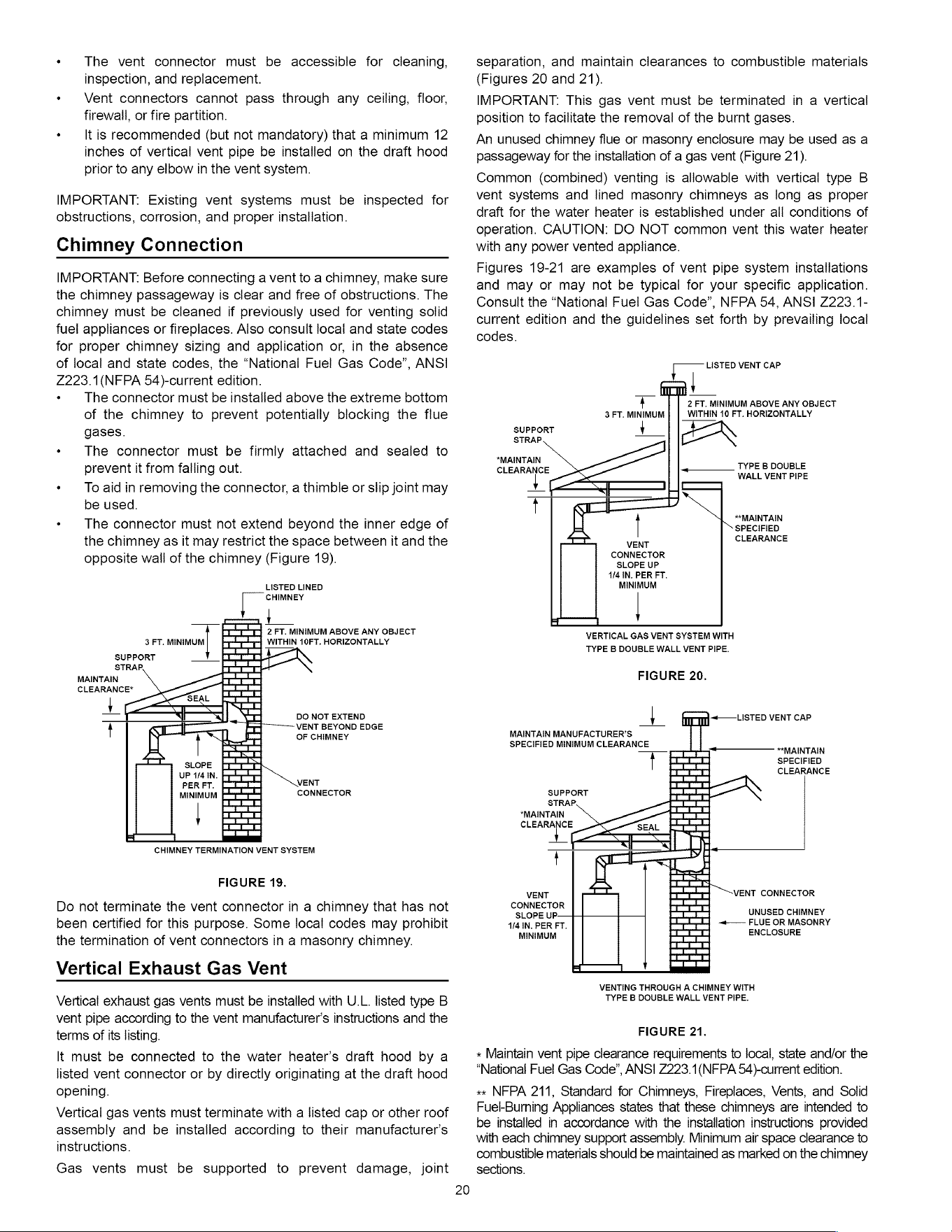
«
The
vent
connector
must
be
accessible
for
cleaning,
inspection,
and
replacement.
«
Vent
connectors
cannot
pass
through
any
ceiling,
floor,
firewall,
or
fire
partition.
+
—
It
is
recommended
(but
not
mandatory)
that
a
minimum
12
inches
of
vertical
vent
pipe
be
installed
on
the
draft
hood
prior
to
any
elbow
in
the
vent
system.
IMPORTANT:
Existing
vent
systems
must
be
inspected
for
obstructions,
corrosion,
and
proper
installation.
Chimney
Connection
IMPORTANT:
Before
connecting
a
vent
to
a
chimney,
make
sure
the
chimney
passageway
is
clear
and
free
of
obstructions.
The
chimney
must
be
cleaned
if
previously
used
for
venting
solid
fuel
appliances
or
fireplaces.
Also
consult
local
and
state
codes
for
proper
chimney
sizing
and application
or,
in
the
absence
of
local
and
state
codes,
the
“National
Fuel
Gas
Code”,
ANSI
Z2223.1(NFPA
54)-current
edition.
«+
The
connector
must
be
installed
above
the
extreme
bottom
of
the
chimney
to
prevent
potentially
blocking
the
flue
gases.
«
The
connector
must
be firmly
attached
and
sealed
to
prevent
it
from
falling
out.
«
To
aid
in
removing
the
connector,
a
thimble
or slip
joint
may
be
used.
«
The
connector
must
not
extend
beyond
the
inner
edge
of
the
chimney
as
it
may
restrict
the
space
between
it
and
the
opposite
wall
of
the
chimney
(Figure
19).
LISTED
LINED
CHIMNEY
i
2
FT.
MINIMUM
ABOVE
ANY
OBJECT
WITHIN
10FT.
HORIZONTALLY
3
FT.
MINIMUM
SUPPORT
STRAP,
MAINTAIN
CLEARANCE*
+
DO
NOT
EXTEND
VENT
BEYOND
EDGE
OF
CHIMNEY
SLOPE
UP
1/4
IN.
PER
FT.
MINIMUM
|
CHIMNEY
TERMINATION
VENT
SYSTEM
VENT
CONNECTOR
FIGURE
19.
Do
not
terminate
the
vent
connector
in
a
chimney
that
has
not
been
certified
for this
purpose.
Some
local
codes
may
prohibit
the
termination
of
vent
connectors
in
a
masonry
chimney.
Vertical
Exhaust
Gas
Vent
Vertical
exhaust
gas
vents
must
be
installed
with
U_L.
listed
type
B
vent
pipe
according
to
the
vent
manufacturer's
instructions
and
the
terms
of
its
listing.
It
must
be
connected
to
the
water
heater’s
draft
hood
by
a
listed
vent
connector
or
by
directly
originating
at
the
draft
hood
opening.
Vertical
gas vents
must
terminate
with
a
listed
cap
or
other
roof
assembly
and
be
installed
according
to
their
manufacturer’s
instructions.
Gas
vents
must
be
supported
to
prevent
damage,
joint
20
separation,
and
maintain
clearances
to
combustible
materials
(Figures
20
and
21).
IMPORTANT:
This
gas
vent
must
be
terminated
in
a
vertical
position
to
facilitate
the
removal
of
the
burnt
gases.
An
unused
chimney
flue
or
masonry
enclosure
may
be
used
as
a
passageway
for
the
installation
of
a
gas
vent
(Figure
21).
Common
(combined)
venting
is
allowable
with
vertical
type
B
vent
systems
and
lined
masonry
chimneys
as
long
as
proper
draft
for
the
water
heater
is
established
under
all
conditions
of
operation.
CAUTION:
DO
NOT
common
vent
this
water
heater
with
any
power
vented
appliance.
Figures
19-21
are
examples
of
vent
pipe
system
installations
and
may
or
may
not
be
typical
for
your
specific
application.
Consult
the
“National
Fuel
Gas
Code”,
NFPA
54,
ANSI
2223.1-
current
edition
and
the
guidelines
set
forth
by
prevailing
local
codes.
LISTED
VENT
CAP
2
FT.
MINIMUM
ABOVE
ANY
OBJECT
WITHIN
10
FT.
HORIZONTALLY
xX
3
FT.
MINIMUM
4
SUPPORT
STRAP
4
MAINTAIN
TYPE
B
DOUBLE
CLEARANCE
WALL
VENT
PIPE
x
[
NY
“MAINTAIN
SPECIFIED
vent
CLEARANCE
CONNECTOR
SLOPE
UP
4/4
IN.
PER
FT.
MINIMUM
|
VERTICAL
GAS
VENT
SYSTEM
WITH
TYPE
B
DOUBLE
WALL
VENT
PIPE.
FIGURE
20.
|
-~«——
LISTED
VENT
CAP
MAINTAIN
MANUFACTURER'S
SPECIFIED
MINIMUM
CLEARANCE
f
*_
*MAINTAIN
SPECIFIED
CLEARANCE
SUPPORT
STRAP.
*MAINTAIN
CLEARANCE
SEAL
x
<
{
—
-_
Lt:
1
L 1
VENT
a
VENT
CONNECTOR
CONNECTOR
7,o
SLOPE
UP.
CI
UNUSED
CHIMNEY
4/4
IN.
PER
FT.
Dot
~—
FLUE
OR
MASONRY
MINIMUM
Dot
ENCLOSURE
|
I
|
Tceed
]
Lend.
el
l
a
VENTING
THROUGH
A
CHIMNEY
WITH
TYPE
B
DOUBLE
WALL
VENT
PIPE.
FIGURE
21.
*
Maintain
vent
pipe
clearance
requirements
to
local,
state
and/or
the
“National
Fuel
Gas
Code”,
ANSI
Z223.1(NFPA
54)-current
edition.
*«
NFPA
211,
Standard
for
Chimneys,
Fireplaces,
Vents,
and
Solid
Fuel-Burning
Appliances
states
that
these
chimneys
are
intended
to
be
installed
in
accordance
with
the
insiallation
instructions
provided
with
each
chimney
support
assembly.
Minimum
air
space
clearance
to
combustible
materials
should
be
maintained
as
marked
on
the
chimney
sections.
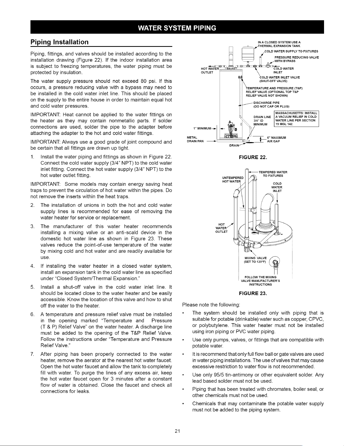
WATER
SYSTEM
PIPING
Piping
Installation
Piping,
fittings,
and
valves
should
be
installed
according
to
the
installation
drawing
(Figure
22).
If
the
indoor
installation
area
is
subject
to
freezing
temperatures,
the
water
piping
must
be
protected
by
insulation.
The
water
supply
pressure
should
not
exceed
80
psi.
If
this
occurs,
a
pressure
reducing
valve
with
a
bypass
may
need
to
be
installed
in
the
cold
water
inlet
line.
This
should
be
placed
on
the
supply
to
the
entire
house
in
order
to
maintain
equal
hot
and
cold
water
pressures.
IMPORTANT:
Heat
cannot
be
applied
to
the
water
fittings
on
the
heater
as
they
may
contain
nonmetallic
parts.
If
solder
connections
are
used,
solder
the
pipe
to
the
adapter
before
attaching
the
adapter
to
the
hot
and
cold
water
fittings.
IMPORTANT:
Always
use
a
good
grade
of
joint
compound
and
be
certain
that
all
fittings
are
drawn
up
tight.
1.
Install
the
water
piping
and
fittings
as
shown
in
Figure
22.
Connect
the
cold
water
supply
(3/4”
NPT)
to
the
cold
water
inlet fitting.
Connect
the
hot
water
supply
(3/4”
NPT)
to
the
hot
water
outlet
fitting.
IMPORTANT:
Some
models
may
contain
energy
saving
heat
traps
to
prevent
the
circulation
of
hot
water
within
the
pipes.
Do
not
remove
the
inserts
within
the
heat
traps.
2.
The
installation
of
unions
in
both
the hot
and
cold
water
supply
lines
is
recommended
for
ease
of
removing
the
water
heater
for
service
or
replacement.
3.
The
manufacturer
of
this
water
heater
recommends
installing
a
mixing
valve
or
an
anti-scald
device
in
the
domestic
hot
water
line
as
shown
in
Figure
23.
These
valves
reduce
the
point-of-use
temperature
of
the
water
by
mixing
cold
and
hot
water
and
are
readily
available
for
use.
4.
If
installing
the
water
heater
in
a
closed
water
system,
install
an
expansion
tank
in
the
cold
water
line
as
specified
under
“Closed
System/Thermal
Expansion.”
5.
Install
a
shut-off
valve
in
the
cold
water
inlet
line.
It
should
be
located
close
to
the
water
heater
and
be
easily
accessible.
Know
the
location
of
this
valve
and
how
to
shut
off
the
water
to
the
heater.
6.
A
temperature
and
pressure
relief
valve
must
be
installed
in
the
opening
marked
“Temperature
and
Pressure
(T
&
P)
Relief
Valve”
on
the
water
heater.
A
discharge
line
must
be
added
to
the
opening
of
the
T&P
Relief
Valve.
Follow
the
instructions
under
“Temperature
and
Pressure
Relief
Valve.”
7.
After
piping
has
been
properly
connected
to
the
water
heater,
remove
the
aerator
at
the
nearest
hot
water
faucet.
Open
the
hot
water
faucet
and
allow
the
tank
to
completely
fill
with
water.
To
purge
the
lines
of
any
excess
air,
keep
the hot
water
faucet
open
for
3
minutes
after
a
constant
flow
of
water
is
obtained.
Close
the
faucet
and
check
alll
connections
for
leaks.
21
IN
A
CLOSED
SYSTEM
USE
A
Oa,
g/
THERMAL
EXPANSION
TANK
COLD
WATER
SUPPLY
TO
FIXTURES
ry
PRESSURE
REDUCING
VALVE
aa
WITH
BYPASS
a
COLD
WATER
INLET
ce
COLD
WATER
INLET
VALVE
(SHUT-OFF
VALVE)
~<—
CL
HOT
WATER
OUTLET
TEMPERATURE
AND
PRESSURE
(T&P)
RELIEF
VALVE
(OPTIONAL
TOP
T&P
RELIEF
VALVE
NOT
SHOWN)
DISCHARGE
PIPE
{DO
NOT
CAP
OR
PLUG)
L
MASSACHUSETTS:
INSTALL
K
DRAIN
LINE
|
A
VACUUM
RELIEF
IN
COLD
3/4"
ID
WATER
LINE
PER
SECTION
MINIMUM
19
MGL
142.
41”
MINIMUM
—»
METAL
~
6”
MAXIMUM
DRAIN
PAN
——»
i
AIR
GAP
DRAIN
FIGURE
22.
rs
+
TEMPERED
WATER
TO
FIXTURES
UNTEMPERED
HOT
WATER
coLb
WATER
waren"
OUTLET
MIXING
VALVE
(SET
TO
120°F)
FOLLOW
THE
MIXING
VALVE
MANUFACTURER’S
INSTRUCTIONS
FIGURE
23.
Please
note
the
following:
«
The
system
should
be
installed
only
with
piping
that
is
suitable
for
potable
(drinkable)
water
such
as
copper,
CPVC,
or
polybutylene.
This
water
heater
must
noi
be
installed
using
iron
piping
or
PVC
water
piping.
«
Use
only
pumps,
valves,
or
fittings
that
are
compatible
with
potable
water.
+
—
|tis
recommend
that
only
full
flow
ball
or
gate
valves
are
used
in
water
piping
installations.
The
use
of
valves
that
may
cause
excessive
restriction
to
water
flow
is
not
recommended.
«
Use
only
95/5
tin-antimony
or
other
equivalent
solder.
Any
lead
based
solder
must
not
be
used.
«
Piping
that
has
been
treated
with
chromates,
boiler
seal,
or
other
chemicals
must
not
be
used.
«
Chemicals
that
may
contaminate
the
potable
water
supply
must
not
be
added
to
the
piping
system.
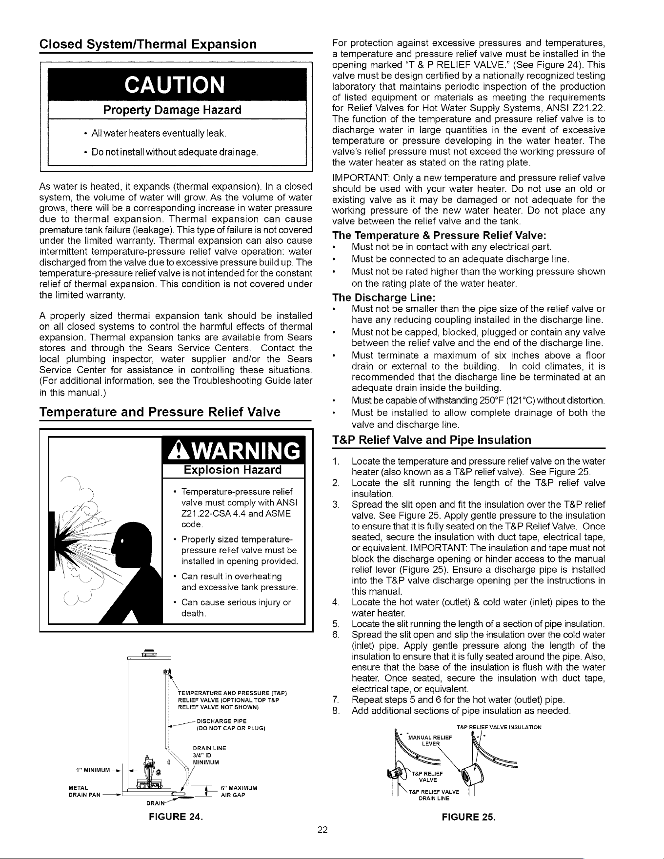
Closed
System/Thermal
Expansion
CAUTION
Property
Damage
Hazard
«
All
water
heaters
eventually
leak.
*
Do
notinstall
without
adequate
drainage.
As
water
is
heated,
it
expands
(thermal
expansion).
In
a
closed
system,
the
volume
of
water
will
grow.
As
the
volume
of
water
grows,
there
will
be
a
corresponding
increase
in
water
pressure
due
to
thermal
expansion.
Thermal
expansion
can
cause
premature
tank
failure
(leakage).
This type
of
failure
is
not
covered
under
the
limited
warranty.
Thermal
expansion
can
also
cause
intermittent
temperature-pressure
relief
valve
operation:
water
discharged
from
the
valve
due
to
excessive
pressure
build
up.
The
temperature-pressure
relief
valve
is
not
intended
for
the
constant
relief
of
thermal
expansion.
This
condition
is
not
covered
under
the
limited
warranty.
A
properly
sized
thermal
expansion
tank
should
be
installed
on
all
closed
systems
to
control
the
harmful
effects
of
thermal
expansion.
Thermal
expansion
tanks
are
available
from
Sears
stores
and
through
the
Sears
Service
Centers.
Contact
the
local
plumbing
inspector,
water
supplier
and/or
the
Sears
Service
Center
for
assistance
in
controlling
these
situations.
(For
additional
information,
see
the
Troubleshooting
Guide
later
in
this
manual.)
Temperature
and
Pressure
Relief
Valve
AWARNING
Explosion
Hazard
*
Temperature-pressure
relief
valve
must
comply
with
ANSI
Z21.22-CSA
4.4
and
ASME
code.
*
Properly
sized
temperature-
pressure
relief
valve
must
be
installed
in
opening
provided.
Can
result
in
overheating
and
excessive
tank
pressure.
*
Can
cause
serious
injury
or
death.
TEMPERATURE
AND
PRESSURE
(T&P)
RELIEF
VALVE
(OPTIONAL
TOP
T&P
RELIEF
VALVE
NOT
SHOWN)
DISCHARGE
PIPE
{DO
NOT CAP
OR
PLUG)
DRAIN
LINE
3/4”
1D
MINIMUM
4”
MINIMUM
—»|
METAL
DRAIN
PAN
——+
6”
MAXIMUM
AIR
GAP
FIGURE
24.
22
For
protection
against
excessive
pressures
and
temperatures,
a
temperature
and
pressure
relief
valve
must
be
installed
in
the
opening
marked
“T &
P
RELIEF
VALVE.”
(See
Figure
24).
This
valve
must
be
design
certified
by
a
nationally
recognized
testing
laboratory
that
maintains
periodic
inspection
of
the
production
of
listed
equipment
or
materials
as
meeting
the
requirements
for
Relief
Valves
for
Hot
Water
Supply
Systems,
ANSI
221.22.
The
function
of
the
temperature
and
pressure
relief
valve
is
to
discharge
water
in
large
quantities
in
the
event
of
excessive
temperature
or
pressure
developing
in
the
water
heater.
The
valve’s
relief
pressure
must
not
exceed
the
working
pressure
of
the
water
heater
as
stated
on
the
rating
plate.
IMPORTANT:
Only
a
new
temperature
and
pressure
relief
vaive
should
be
used
with
your
water
heater.
Do
not
use
an
old
or
existing
valve
as
it
may
be
damaged
or
not
adequate
for
the
working
pressure
of
the
new
water
heater.
Do
not
place
any
valve
between
the
relief
valve
and
the
tank.
The
Temperature
&
Pressure
Relief
Valve:
«
Must
not
be
in
contact
with
any
electrical
part.
+
Must
be
connected
to
an
adequate
discharge
line.
«+
Must
not
be
rated
higher
than
the
working
pressure
shown
on
the
rating plate
of
the
water
heater.
Discharge
Line:
Must
not
be
smaller
than
the
pipe
size
of
the
relief
valve
or
have
any
reducing
coupling
installed
in
the
discharge
line.
«+
Must
not
be
capped,
blocked,
plugged
or
contain
any
valve
between
the
relief
valve
and
the
end
of
the
discharge
line.
+
Must
terminate
a
maximum
of
six
inches
above
a
floor
drain
or
external
to
the
building.
In
cold
climates,
it
is
recommended
that
the
discharge
line
be
terminated
at
an
adequate
drain
inside
the
building.
«
Must
be
capable
of
withstanding
250°F
(121°C)
without
distortion.
«
Must
be
installed
to
allow
complete
drainage
of
both
the
valve
and
discharge
line.
T&P
Relief
Valve
and
Pipe
Insulation
The
1.
Locate
the
temperature
and
pressure
relief
valve
on
the
water
heater
(also
known
as
a
T&P
relief
valve).
See
Figure
25.
2.
Locate
the
slit
running
the
length
of
the
T&P
relief
valve
insulation.
3.
Spread
the
slit
open
and
fit
the
insulation
over
the
T&P
relief
valve.
See
Figure
25.
Apply
gentle
pressure
to
the
insulation
to
ensure
that
itis
fully
seated
on
the
T&P
Relief
Valve.
Once
seated,
secure
the
insulation
with
duct
tape,
electrical
tape,
or
equivalent.
IMPORTANT:
The
insulation
and
tape
must
not
block
the
discharge
opening
or
hinder
access
to
the
manual
relief
lever
(Figure
25).
Ensure
a
discharge
pipe
is
installed
into
the
T&P
valve
discharge
opening
per
the
instructions
in
this
manual.
4.
Locate
the
hot
water
(outlet)
&
cold
water
(inlet)
pipes
to
the
water
heater.
5.
Locate
the
slit
running
the
length
of
a
section
of
pipe
insulation.
6.
Spread
the
slit
open
and
slip
the
insulation
over
the
cold
water
(inlet)
pipe.
Apply
gentle
pressure
along
the
length
of
the
insulation
to
ensure
that
it
is
fully
seated
around
the
pipe.
Also,
ensure
that
the
base
of
the
insulation
is
flush
with
the
water
heater.
Once
seated,
secure
the
insulation
with
duct
tape,
electrical
tape,
or
equivalent.
7.
Repeat
steps
5
and
6
for
the hot
water
(outlet)
pipe.
8.
Add
additional
sections
of
pipe
insulation
as
needed.
T&P
RELIEF
VALVE
INSULATION
°
"MANUAL
RELIEF
-/[-
LEVER
T&P
RELIEF
VALVE
T&P
RELIEF
VALVE
DRAIN
LINE
FIGURE
25.
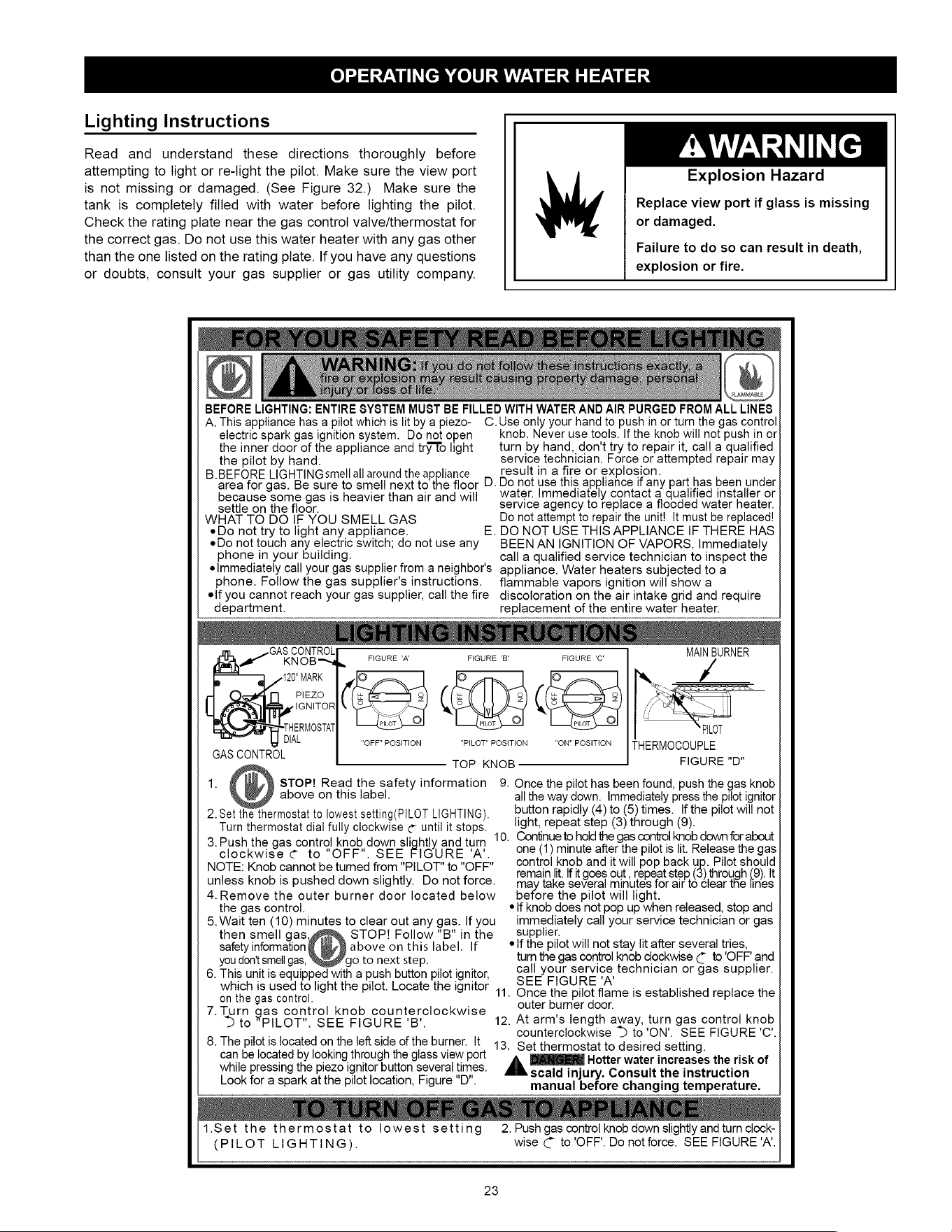
OPERATING
YOUR
WATER
HEATER
Lighting
Instructions
AWARNING
Explosion
Hazard
Read
and
understand
these
directions
thoroughly
before
attempting
to
light or
re-light
the
pilot.
Make
sure
the
view
port
is
not
missing
or
damaged.
(See
Figure
32.)
Make
sure
the
tank
is
completely
filled
with
water
before
lighting
the
pilot.
Check
the
rating
plate
near
the
gas
control
valve/thermostat
for
the
correct
gas.
Do
not
use
this
water
heater
with
any gas
other
than
the
one
listed
on
the
rating
plate.
If
you
have
any
questions
or
doubts,
consult
your
gas
supplier
or
gas
utility
company.
Replace
view
port
if
glass
is
missing
or
damaged.
Failure
to
do
so
can
result
in
death,
explosion
or
fire.
BEFO
RE
LIGHTING:
ENTIRE
SYSTEM
MUST
BE
FILLED
WITH
WATER
AND
AIR
PURGED
FROM
ALL
LINES
A.
This
appliance
has
a
pilot
which
is
lit
by
a
piezo-
C.Use
only
your
hand
to
push
in
or
turn
the
gas
control
knob.
Never
use
tools.
If
the
knob
will
not
push
in
or
electric
spark
gas
ignition
system.
Do
not
open
ob
;
turn
by
hand,
don't
try
to
repair
it,
call
a
qualified
the
inner
door
of
the
appliance
and
try
To
light
service
technician.
Force
or
attempted
repair
may
result
in
a
fire
or
explosion.
Do
not
use
this
appliance
if
any
part
has
been
under
water.
Immediately
contact
a
qualified
installer
or
service
agency
to
replace
a
flooded
water
heater.
Do
not
attempt
to
repair
the
unit!
It
must
be
replaced!
DO
NOT
USE
THIS
APPLIANCE
IF
THERE
HAS
BEEN
AN
IGNITION
OF
VAPORS.
Immediately
call
a
qualified
service
technician
to
inspect
the
appliance.
Water
heaters
subjected
to
a
flammable
vapors
ignition
will
show
a
discoloration
on
the
air
intake
grid
and
require
replacement
of
the
entire
water
heater.
the
pilot
by
hand.
B.BEFORE
LIGHTING
smell
all
around
the
appliance
area
for
gas.
Be
sure
to
smell
next
to
the
floor
D.
because
some
gas
is
heavier
than
air
and
will
settle
on
the
floor.
WHAT
TO
DO
IF
YOU
SMELL
GAS
«Do
not
try
to
light
any
appliance.
eDo
not
touch any
electric
switch;
do
not
use
any
phone
in
your
building.
elmmediately
call
your
gas
supplier
from
a
neighbor's
phone.
Follow
the
gas
supplier's
instructions.
elf
you
cannot
reach
your
gas
supplier,
call
the
fire
department.
E.
MAIN
BURNER
CAS
CONTROL
KNOB™d
FIGURE
‘A’
FIGURE
'B'
FIGURE
'C'
——
120°
MARK
Oo
o
ei
ie
Gibelese
Ce
SET
IGNITOR|
YZ
AN
ZA
gsuosta
[fas
ol
“Ltt
ol
:
DIAL
“OFF”
POSITION
“PILOT”
POSITION
"ON"
POSITION
THERMOCOUPLE
GAS
CONTROL
re
se
TOP
KNOB
FIGURE
"D
)
STOP!
Read
the
safety
information
9.
Once
the
pilot
has
been
found,
push
the
gas
knob
above
on
this
label.
all
the
way
down.
Immediately
press
the
pilot
ignitor
2
Set
the
thermostat
to
lowest
setting(PILOT
LIGHTING),
button
rapidly
(4)
to
(5)
times.
If
the
pilot
will
not
Turn
thermostat
dial
fully
clockwise
¢
until
it
stops.
light,
repeat
step
(3)
through
(9).
3.
Push
the
gas
control
knob
down
slightly
and
tum
10.
Continue
to
hold
the
gas
control
knob
down
for
about
clockwise
¢
to
"OFF".
SEE
URE
‘A’.
one
(1)
minute
after
the
pilot
is
lit.
Release
the
gas
:
¥
ar
«
control
knob
and
it
will
pop
back
up.
Pilot
should
MO
ee
noe
cannot
be
fumed
rom
ib,
T
0
2
FP
remain
lit.
If
it
goes
out
,
repeat
step
3)
through
(°).
lt
uniéss
KnNod
IS
pusned
Gown
siignuy.
VO
Nollorce.
—
may
take
several
minutes
for
air
to
clear
the
lines
before
the
pilot
will
light.
*If
knob
does
not
pop
up
when
released,
stop
and
immediately
call
your service
technician
or
gas
supplier.
elf
the
pilot
will
not
stay
lit
after
several
tries,
turn
the
gas
control
knob
clockwise
@
to
'OFF'
and
call
your
service
technician
or
gas
supplier.
SEE
FIGURE
'A'
.
Once
the
pilot
flame
is
established
replace
the
outer
burner
door.
12.
At
arm's
length
away,
turn
gas
control
knob
counterclockwise
>
to'ON'.
SEE
FIGURE'C’.
13.
Set
thermostat
to
desired
setting.
A
Hotter
water
increases
the
risk
of
scald
injury.
Consult
the
instruction
manual
before
changing
temperature.
4.Remove
the
outer
burner
door
located
below
the
gas
control.
5.
Wait
ten
(10)
minutes
to
clear
out
any
gas.
If
you
then
smell
gas,@@
™,
STOP!
Follow
"B"
in
the
safety
information|
/
|
above
on
this
label.
If
you
don't
smell
gas,
“gr
6.
This
unit
is
equipped
with
a
push
button
pilot
ignitor,
which
is
used
to
light
the
pilot.
Locate
the
ignitor
1
on
the
gas
control.
7.
Turn
gas
control
knob
counterclockwise
>
to
"PILOT".
SEE
FIGURE
'B'.
8.
The
pilot
is
located
on
the
left
side
of
the
burner.
it
can
be
located
by
looking
through
the
glass
view
port
while
pressing
the
piezo
ignitor
button
several
times.
Look
for
a
spark
at
the
pilot
location,
Figure
"D".
{tum
clock-
wise
C
to
'OFF'.
Do
not
force.
SEE
FIGURE
'A’.
i1.Set
the
therm
at to
lowest
setting
2.
Push
gas
control
knob
down
slightly
a
(PILOT
LIGHTING).
23
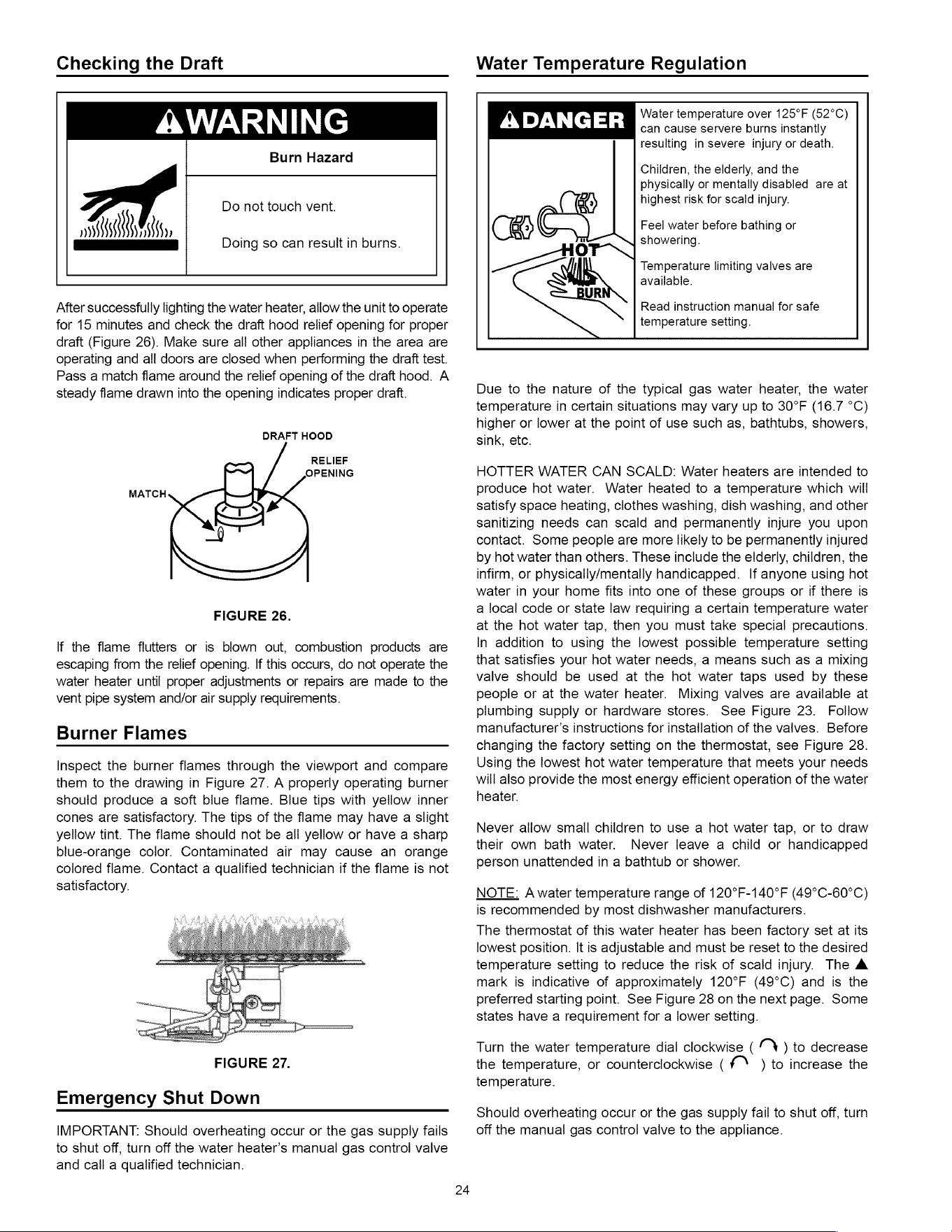
Checking
the
Draft
Water
Temperature
Regulation
AWARNING
Burn
Hazard
Do
not
touch
vent.
DANN,
es
Doing
so
can
result
in
burns.
After
successfully
lighting
the
water
heater,
allow
the
unit
to
operate
for
15
minutes
and
check
the
draft
hood
relief
opening
for
proper
draft
(Figure
26).
Make
sure
all
other
appliances
in
the
area
are
operating
and
all
doors
are
closed
when
performing
the
draft
test.
Pass
a
match
flame
around
the
relief
opening
of
the
draft
hood.
A
steady
flame
drawn
into
the
opening
indicates
proper
draft.
DRAFT
HOOD
RELIEF
P
OPENING
eh
<=
NF
FIGURE
26.
MATCH
lf
the
flame
flutters
or
is
blown
out,
combustion
products
are
escaping
from
the
relief
opening.
If
this
occurs,
do
not
operate
the
water
heater
until
proper
adjustments
or
repairs
are
made
to
the
vent
pipe
system
and/or
air
supply
requirements.
Burner
Flames
Inspect
the
burner
flames
through
the
viewport
and
compare
them
to
the
drawing
in
Figure
27.
A
properly
operating
burner
should
produce
a
soft
blue
flame.
Blue
tips
with
yellow
inner
cones
are
satisfactory.
The
tips
of
the
flame
may
have
a
slight
yellow
tint.
The
flame
should
not
be
all
yellow
or
have
a
sharp
blue-orange
color.
Contaminated
air
may
cause
an
orange
colored
flame.
Contact
a
qualified
technician
if
the
flame
is
not
satisfactory.
FIGURE
27.
Emergency
Shut
Down
IMPORTANT:
Should
overheating
occur
or
the
gas
supply
fails
to
shut
off,
turn
off
the
water
heater’s
manual
gas
control
valve
and
call
a
qualified
technician.
Water
temperature
over
125°F
(52°C)
ry
DANGER
can
cause
servere
burns
instantly
resulting
in
severe
injury
or
death.
Children,
the
elderly,
and
the
physically
or
mentally disabled
are
at
highest
risk
for
scald
injury.
CR
Feel
water
before
bathing
or
Tr
showering.
Temperature
limiting
valves
are
available.
UR
Read
instruction
manual
for
safe
temperature
setting.
Due
to
the
nature
of
the
typical
gas
water
heater,
the
water
temperature
in
certain
situations
may
vary
up
to
30°F
(16.7
°C)
higher
or
lower
at
the
point
of
use
such
as,
bathtubs,
showers,
sink,
etc.
HOTTER
WATER
CAN
SCALD:
Water
heaters
are
intended
to
produce
hot
water.
Water
heated
to
a
temperature
which
will
satisfy
space
heating,
clothes
washing,
dish
washing,
and
other
sanitizing
needs
can scald
and
permanently
injure
you
upon
contact.
Some
people
are
more
likely
to
be
permanently
injured
by
hot
water
than
others.
These
include
the
elderly,
children,
the
infirm,
or
physically/mentally
handicapped.
If
anyone
using
hot
water
in
your
home
fits
into
one
of
these
groups
or
if
there
is
a
local
code
or
state
law
requiring
a
certain
temperature
water
at
the
hot
water
tap,
then
you
must
take
special
precautions.
In
addition
to
using
the
lowest
possible
temperature
setting
that
satisfies
your
hot
water
needs,
a
means
such
as
a
mixing
valve
should
be
used
at
the hot
water
taps
used
by
these
people
or
at
the
water
heater.
Mixing
valves
are
available
at
plumbing
supply
or
hardware
stores.
See
Figure
23.
Follow
manufacturer’s
instructions
for
installation
of
the
valves.
Before
changing
the
factory
setting
on
the
thermostat,
see
Figure
28.
Using
the
lowest
hot
water
temperature
that
meets
your
needs
will
also
provide
the
most
energy
efficient
operation
of
the
water
heater.
Never
allow
small
children
to
use
a
hot
water
tap,
or
to
draw
their
own
bath
water.
Never
leave
a
child
or
handicapped
person
unattended
in
a
bathtub
or
shower.
NOTE:
A
water
temperature
range
of
120°F-140°F
(49°C-60°C)
is
recommended
by
most
dishwasher
manufacturers.
The
thermostat
of
this
water
heater
has
been
factory
set
at
its
lowest
position.
It
is
adjustable
and
must
be
reset
to
the
desired
temperature
setting
to
reduce
the
risk
of
scald
injury.
The
&
mark
is
indicative
of
approximately
120°F
(49°C)
and
is
the
preferred
starting
point.
See
Figure
28
on
the
next
page.
Some
states
have
a
requirement
for
a
lower
setting.
Turn
the
water
temperature
dial
clockwise
(
N
)
to
decrease
the
temperature,
or
counterclockwise
(
f
)
to
increase
the
temperature.
Should
overheating
occur
or
the
gas
supply
fail
to
shut
off,
turn
off
the
manual
gas
control
valve
to
the
appliance.
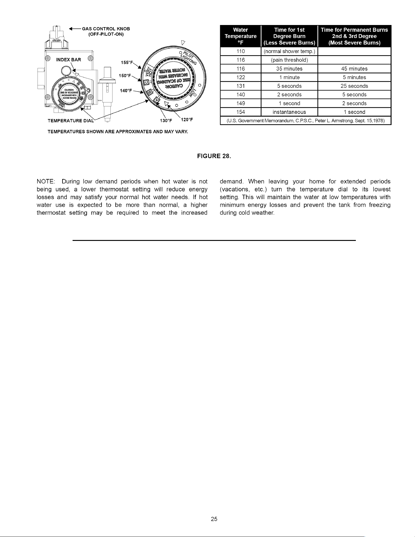
<—
GAS
CONTROL
KNOB
(OFF-PILOT-ON)
110
(normal
shower
temp.)
116
(pain
threshold)
116
35
minutes
45
minutes
122
1
minute
5
minutes
134
5
seconds
25
seconds
140
2
seconds
5
seconds
149
1
second
2
seconds
154
instantaneous
1
second
(U.S.
Government
Memorandum,
C.P.S.C.,
Peter
L.
Armstrong,
Sept.
15,1978)
TEMPERATURES
SHOWN
ARE
APPROXIMATES
AND
MAY
VARY.
FIGURE
28.
NOTE:
During
low
demand
periods
when
hot
water
is
not
demand.
When
leaving
your
home
for
extended
periods
being
used,
a
lower
thermostat
setting
will
reduce
energy
(vacations,
etc.)
turn
the
temperature
dial
to
its
lowest
losses
and
may
satisfy
your
normal
hot
water
needs.
If
hot
seiting.
This
will
maintain
the
water
at
low
temperatures
with
water
use
is
expected
to
be
more
than
normal,
a
higher
minimum
energy
losses
and
prevent
the
tank
from
freezing
thermostat
setting
may
be
required
to
meet
the
increased
during
cold
weather.
25
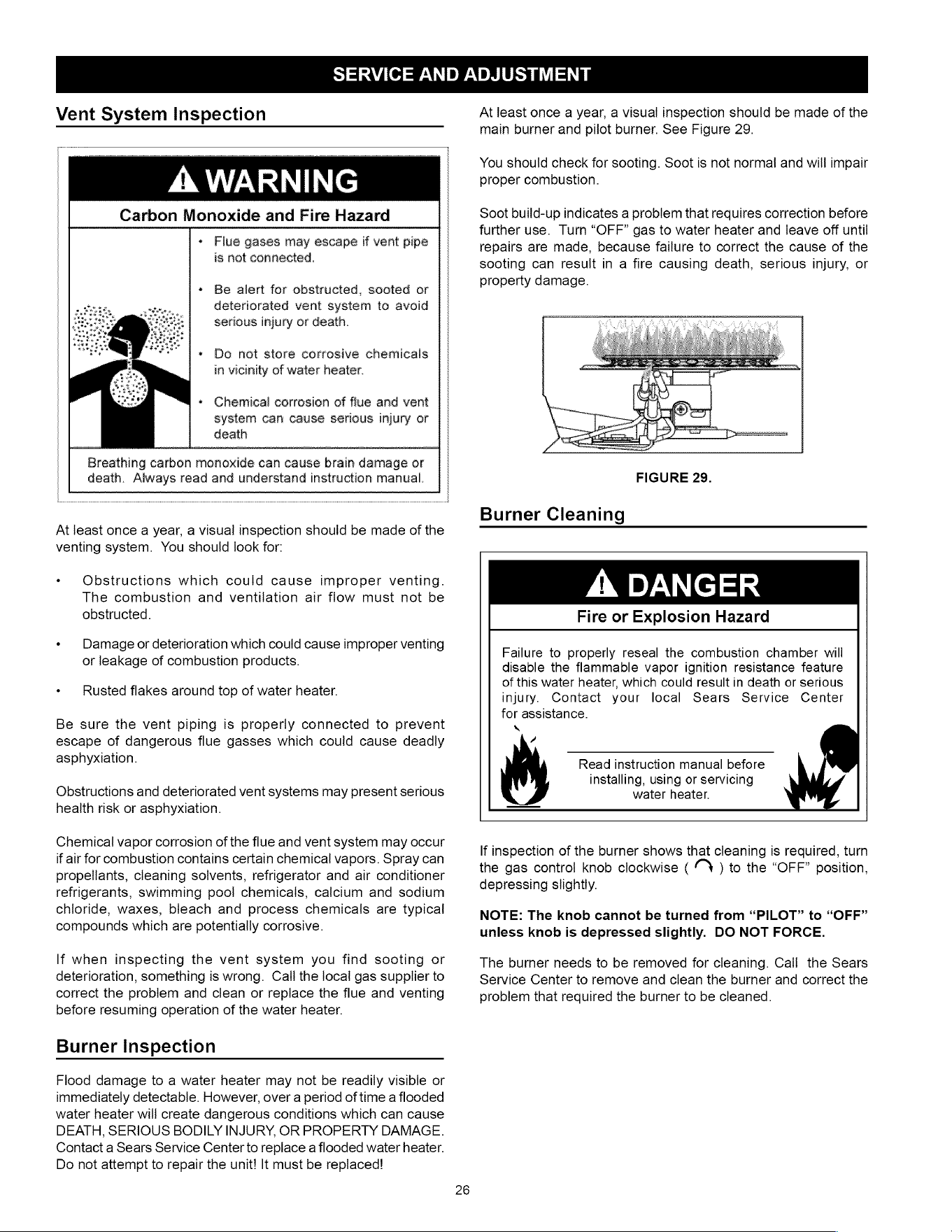
SERVICE
AND
ADJUSTMENT
Vent
System
Inspection
Ie
Carbon
Monoxide
and
Fire
Hazard
*
Flue
gases
may
escape
if
vent
pipe
is
not
connected.
«
Be
alert
for
obstructed,
sooted
or
deteriorated
vent
system
to
avoid
serious
injury
or
death.
+
Do
not
store
corrosive
chemicals
in
vicinity
of
water
heater.
*
Chemical
corrosion
of
flue
and
vent
system
can
cause
serious
injury
or
death
Breathing
carbon
monoxide
can
cause
brain
damage
or
death.
Always
read
and
understand
instruction
manual.
At
least
once
a
year,
a
visual
inspection
should
be
made
of
the
venting
system.
You
should
look
for:
*
Obstructions
which
could
cause
improper
venting.
The
combustion
and
ventilation
air
flow
must
not
be
obstructed.
«
Damage
or
deterioration
which
could
cause
improper
venting
or
leakage
of
combustion
products.
«
Rusted
flakes
around
top
of
water
heater.
Be
sure
the
vent
piping
is
properly
connected
to
prevent
escape
of
dangerous
flue
gasses
which
could
cause
deadly
asphyxiation.
Obstructions
and
deteriorated
vent
systems
may
present
serious
health
risk
or
asphyxiation.
Chemical
vapor
corrosion
of
the
flue
and
vent
system
may
occur
if
air
for
combustion
contains
certain
chemical
vapors.
Spray
can
propellants,
cleaning
solvents,
refrigerator
and
air
conditioner
refrigerants,
swimming
pool
chemicals,
calcium
and
sodium
chloride,
waxes,
bleach
and
process
chemicals
are
typical
compounds
which
are
potentially
corrosive.
lf
when
inspecting
the
vent
system
you
find
sooting
or
deterioration,
something
is
wrong.
Call
the
local
gas
supplier
to
correct
the
problem
and
clean
or
replace
the
flue
and
venting
before
resuming
operation
of
the
water
heater.
Burner
Inspection
Flood
damage
to
a
water
heater
may
not
be
readily
visible
or
immediately
detectable.
However,
over
a
period
of
time
a
flooded
water
heater
will
create
dangerous
conditions
which
can
cause
DEATH,
SERIOUS
BODILY
INJURY,
OR
PROPERTY
DAMAGE.
Contact
a
Sears
Service
Center
to
replace
a
flooded
water
heater.
Do
not
attempt
to
repair
the
unit!
It
must
be
replaced!
26
At
least
once
a
year,
a
visual
inspection
should
be
made
of
the
main
burner
and
pilot
burner.
See
Figure
29.
You
should
check
for
sooting.
Soot
is
not
normal
and
will
impair
proper
combustion.
Soot
build-up
indicates
a
problem
that
requires
correction
before
further
use.
Turn
“OFF”
gas
to
water
heater
and
leave
off
until
repairs
are
made,
because
failure
to
correct
the
cause
of
the
sooting
can
result
in
a
fire
causing
death,
serious
injury,
or
property
damage.
FIGURE
29.
Burner
Cleaning
A
DANGER
Fire
or
Explosion
Hazard
Failure
to
properly
reseal
the
combustion
chamber
will
disable
the
flammable
vapor
ignition
resistance
feature
of
this
water
heater,
which
could
result
in
death
or
serious
injury.
Contact
your
local
Sears
Service
Center
for
assistance.
Q
7
Read
instruction
manual
before
installing,
using
or
servicing
water
heater.
If
inspection
of
the
burner
shows
that
cleaning
is
required,
turn
the
gas
control
knob
clockwise
(
N
)
to
the
“OFF”
position,
depressing
slightly.
NOTE:
The
knob
cannot
be
turned
from
“PILOT”
to
“OFF”
unless
knob
is
depressed
slightly.
DO
NOT
FORCE.
The
burner
needs
to
be
removed
for
cleaning.
Call
the
Sears
Service
Center
to
remove
and
clean
the
burner
and
correct
the
problem
that
required
the
burner
to
be
cleaned.
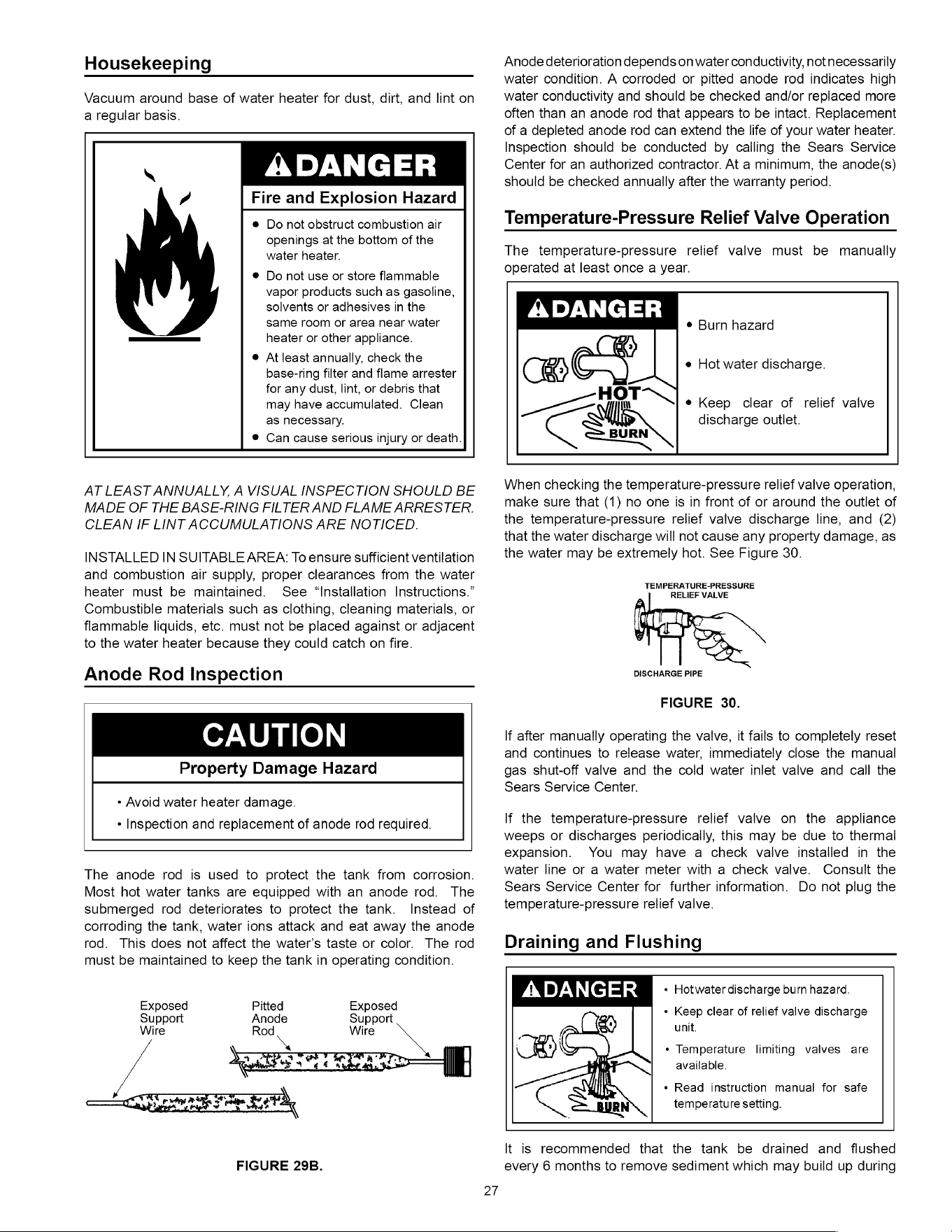
Housekeeping
Vacuum
around
base
of
water
heater
for
dust,
dirt,
and
lint
on
a
regular
basis.
”
Fire
and
Explosion
Hazard
@
Do
not
obstruct
combustion
air
openings
at
the
bottom
of
the
water
heater.
®
Do
not
use
or
store
flammable
vapor
products
such
as
gasoline,
solvents
or
adhesives
in
the
same
room
or
area
near
water
heater
or
other
appliance.
e@
At
least
annually,
check
the
base-ring
filter
and
flame
arrester
for
any
dust,
lint,
or
debris
that
may
have
accumulated.
Clean
as
necessary.
®
Can
cause
serious
injury
or
death.
AT
LEAST
ANNUALLY,
A
VISUAL
INSPECTION
SHOULD
BE
MADE
OF
THE
BASE-RING
FILTER
AND
FLAME
ARRESTER.
CLEAN
IF
LINT
ACCUMULATIONS
ARE
NOTICED.
INSTALLED
IN
SUITABLE
AREA:
To
ensure
sufficient
ventilation
and
combustion
air
supply,
proper
clearances
from
the
water
heater
must
be
mainiained. See
“Installation
Instructions.”
Combustible
materials
such
as
clothing,
cleaning
materials,
or
flammable
liquids,
etc.
must
not
be
placed
against
or
adjacent
to
the
water
heater
because
they
could
catch
on
fire.
Anode
Rod
Inspection
CAUTION
Property
Damage
Hazard
¢
Avoid water
heater
damage.
*
Inspection
and
replacement
of
anode
rod
required.
The
anode
rod
is
used
to
protect
the
tank
from
corrosion.
Most
hot
water
tanks
are
equipped
with
an
anode
rod.
The
submerged
rod
deteriorates
to
protect
the
tank.
Instead
of
corroding
the
tank,
water
ions
attack
and
eat
away
the
anode
rod.
This
does
not
affect
the
water’s
taste
or
color.
The
rod
must
be
maintained
to
keep
the
tank
in
operating
condition.
Exposed
Pitted
Exposed
Support
Anode
Support
Wire
Rod
Wire
\,
FIGURE
29B.
Anode
deterioration
depends
on
water
conductivity,
not
necessarily
water
condition.
A
corroded
or
pitted
anode
rod
indicates
high
water
conductivity
and
should
be
checked
and/or
replaced
more
often
than
an
anode
rod
that
appears
to
be
intact.
Replacement
of
a
depleted
anode
rod
can
extend
the
life
of
your
water
heater.
Inspection
should
be
conducted
by
calling
the
Sears
Service
Center
for
an
authorized
contractor.
At
a
minimum,
the
anode(s)
should
be
checked
annually
after
the
warranty
period.
Temperature-Pressure
Relief
Valve
Operation
The
temperature-pressure
relief
valve
must
be
manually
operated
at
least
once
a
year.
ADANGER
®
Burn
hazard
e
Hot
water
discharge.
=
nm
oN
e
Keep
clear
of
relief
valve
discharge
outlet.
BURN
When
checking
the
temperature-pressure
relief
valve
operation,
make
sure
that
(1)
no
one
is
in
front
of
or
around
the
outlet
of
the
temperature-pressure
relief
valve
discharge
line,
and
(2)
that
the
water
discharge
will
not
cause
any
property
damage,
as
the
water
may
be
extremely
hot.
See
Figure
30.
TEMPERATURE-PRESSURE
RELIEF
VALVE
DISCHARGE
PIPE
FIGURE
30.
lf
after
manually
operating
the
valve,
it
fails
to
completely
reset
and
continues
to
release
water,
immediately
close
the
manual
gas
shut-off
valve
and
the
cold
water
inlet
valve
and
call
the
Sears
Service
Center.
lf
the
temperature-pressure
relief
valve
on
the
appliance
weeps
or
discharges
periodically,
this
may
be
due
to
thermal
expansion.
You
may
have
a
check
valve
installed
in
the
water
line
or
a
water
meter
with
a
check
valve.
Consult
the
Sears
Service
Center
for
further
information.
Do
not
plug
the
temperature-pressure
relief
valve.
Draining
and
Flushing
ADANGER
«
Hotwater
discharge
burn
hazard.
«
Keep
clear
of
relief
valve
discharge
unit.
¢
Temperature
limiting
valves
are
available.
«
Read
instruction
manual
for
safe
temperature
setting.
It
is
recommended
that
the
tank
be
drained
and
flushed
every
6
months
to
remove
sediment
which
may
build
up
during
operation.
The
water
heater
should
be
drained
if
being
shut
down
during
freezing
temperatures.
To
drain
the
tank,
perform
the
following
steps:
1.
Turn
off
the
gas
to
the
water
heater
at
the
manual
gas
shut-off
valve.
2.
Open
a
nearby
hot
water
faucet
until
the
water
is
no
longer
hot.
3.
Close
the
cold
water
inlet
valve.
4.
Connect
a
hose
to
the
drain
valve
and
terminate
it
to
an
adequate
drain
or
external
to
the
building.
5.
Open
the
water
heater
drain
valve
and
allow
all
of
the
water
to
drain
from
the
tank.
Flush
the
tank
with
water
as
needed
to
remove
sediment.
6.
Close
the
drain
valve,
refill
the
tank,
and
restart
the
heater
as
directed
in
this
manual.
lf
the
water
heater
is
going
to
be
shut
down
for
an
extended
period,
the
drain
valve
should
be
left
open.
IMPORTANT:
Condensation
may
occur
when
refilling
the
tank
and
should
not
be
confused
with
a
tank
leak.
Service
Before
calling
for
repair
service,
please
read
the
Troubleshooting
Guide
in
this
manual.
If
a
condition
persists
or
you
are
uncertain
about
the
operation
of
the
water
heater,
let
the
Sears
Service
Center
check
it
out.
Contact
Sears
Service
Center
at:
1-800-4-MY-HOME®
(1-800-469-4663).
28
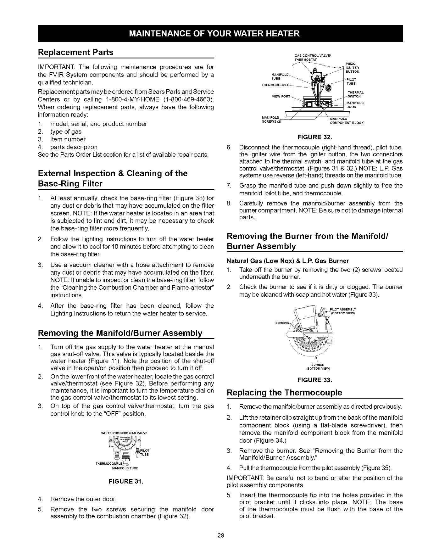
MAINTENANCE
OF
YOUR
WATER
HEATER
Replacement
Parts
IMPORTANT:
The
following
maintenance
procedures
are
for
the
FVIR
System
components
and
should
be
performed
by
a
qualified
technician.
Replacement
parts
may
be
ordered
from
Sears
Parts
and
Service
Centers
or
by
calling
1-800-4-MY-HOME
(1-800-469-4663).
When
ordering
replacement
parts,
always
have
the
following
information
ready:
1.
model,
serial,
and
product
number
2.
type
of
gas
3.
item
number
4.
parts
description
See
the
Parts
Order
List
section
for
a
list
of
available
repair
parts.
External
Inspection
&
Cleaning
of
the
Base-Ring
Filter
1.
Atleast
annually,
check
the
base-ring
filter
(Figure
38)
for
any
dust
or
debris
that
may
have
accumulated
on
the
filter
screen.
NOTE:
If
the
water
heater
is
located
in
an
area
that
is
subjected
to
lint
and
dirt,
it
may
be
necessary
to
check
the
base-ring
filter
more
frequently.
2.
Follow
the
Lighting
Instructions
to
turn
off
the
water
heater
and
allow
it
to
cool
for
10
minutes
before
attempting
to
clean
the
base-ring
filter.
3.
Use
a
vacuum
cleaner
with
a
hose
attachment
to
remove
any
dust
or
debris
that
may
have
accumulated
on
the
filter.
NOTE:
If
unable
to
inspect
or
clean
the
base-ring
filter,
follow
the
“Cleaning
the
Combustion
Chamber
and
Flame-arrestor”
instructions.
4.
After
the
base-ring
filter
has
been
cleaned,
follow
the
Lighting
Instructions
to
return
the
water
heater
to
service.
Removing
the
Manifold/Burner
Assembly
1.
Turn
off
the
gas
supply
to
the
water
heater
at
the
manual
gas
shut-off
valve.
This
valve
is
typically
located
beside
the
water
heater
(Figure
11).
Note
the
position
of
the
shut-off
valve
in
the
open/on
position
then
proceed
to
turn
it
off.
2.
Onthe
lower
front
of
the
water
heater,
locate
the
gas
control
valve/thermostat
(see
Figure
32).
Before
performing
any
maintenance,
it
is
important
to
turn
the
temperature
dial
on
the
gas
control
valve/thermostat
to
its
lowest
setting.
3.
On
top
of
the
gas
control
valve/thermostat,
turn
the
gas
control
knob
to
the
“OFF”
position.
WHITE
RODGERS
GAS
VALVE
Y
unsooncse
eae
PILOT
7
Le
Fuse
iT
THERMOCOUPLE
=
MANIFOLD
TUBE
FIGURE
31.
4.
Remove
the
outer
door.
5.
Remove
the
two
screws
securing
the
manifold
door
assembly
to
the
combustion
chamber
(Figure
32).
GAS
CONTROL
VALVE/
THERMOSTAT
PIEZO
IGNITER
BUTTON
MANIFOLD
TUBE
PILOT
THERMOCOUPLE-+
TUBE
THERMAL
VIEW
PORT
SWITCH
|_
MANIFOLD
|
DOOR
MANIFOLD
COMPONENT
BLOCK
MANIFOLD
SCREWS
(2)
FIGURE
32.
6.
Disconnect
the
thermocouple
(right-hand
thread),
pilot
tube,
the
igniter
wire
from
the
igniter
button,
the
two
connectors
attached
to
the
thermal
switch,
and
manifold
tube
at
the
gas
control
valve/thermostat.
(Figures
31
&
32.)
NOTE:
L.P.
Gas
systems
use
reverse
(left-hand)
threads
on
the
manifold
tube.
7.
Grasp
the
manifold
tube
and
push
down
slightly
to
free
the
manifold,
pilot
tube,
and
thermocouple.
8.
Carefully
remove
the
manifoild/ourner
assembly
from
the
burner
compartment.
NOTE:
Be sure
not
to
damage
internal
parts.
Removing
the
Burner
from
the
Manifold/
Burner
Assembly
Natural
Gas
(Low
Nox)
&
L.P.
Gas
Burner
1.
Take
off
the
burner
by
removing
the
two
(2)
screws
located
underneath
the
burner.
2.
Check
the
burner
to
see
if
it
is
dirty
or
clogged.
The
burner
may
be
cleaned
with
soap
and
hot
water
(Figure
33).
BURNER
(BOTTOM
VIEW)
FIGURE
33.
Replacing
the
Thermocouple
1.
Remove
the
manifold/burner
assembly
as
directed
previously.
2.
Liftthe
retainer
clip
straight
up
from
the
back
of
the
manifold
component
block
(using
a
flat-blade
screwdriver),
then
remove
the
manifold
component
block
from
the
manifold
door
(Figure
34.)
3.
Remove
the
burner.
See
“Removing
the
Burner
from
the
Manifold/Burner
Assembly.”
4,
Pull
the
thermocouple
from
the
pilot
assembly
(Figure
35).
IMPORTANT:
Be
careful
not
to
bend
or
alter
the
position
of
the
pilot
assembly
components.
5.
Insert
the
thermocouple
tip
into
the
holes
provided
in
the
pilot
bracket
until
it
clicks
into
place.
NOTE:
The
base
of
the
thermocouple
must
be
flush
with
the
base
of
the
pilot
bracket.
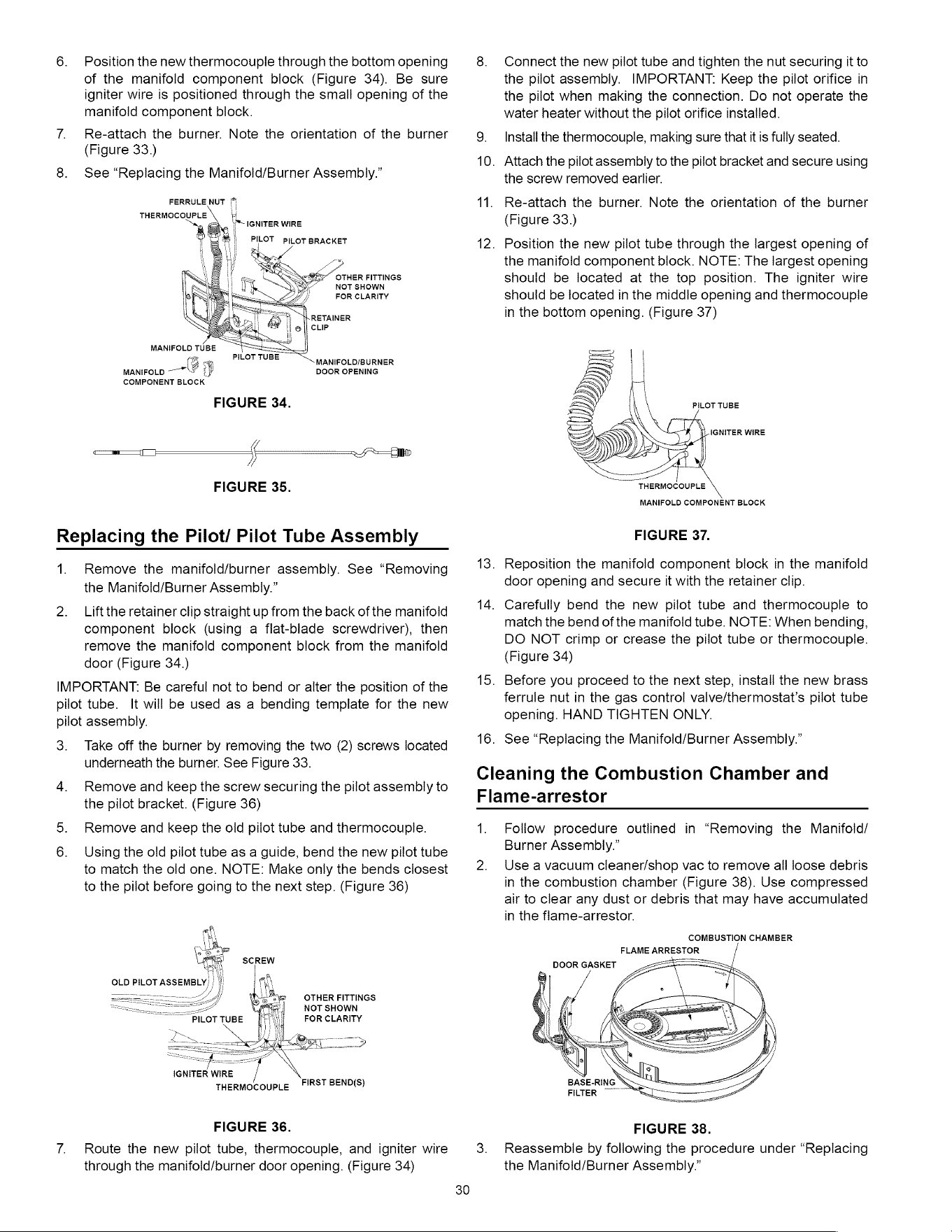
6.
Position
the
new
thermocouple
through
the
bottom
opening
of
the
manifold
component
biock
(Figure
34).
Be
sure
igniter
wire
is
positioned
through
the
small
opening
of
the
manifold
component
block.
7.
Re-attach
the
burner.
Note
the
orientation
of
the
burner
(Figure
33.)
8.
See
“Replacing
the
Manifold/Burner
Assembly.”
am
FERRULE
NUT
©
THERMOCOUPLE
i
NOT
SHOWN
FOR
CLARITY
MANIFOLD
TUBE
(3
.
PILOT
TUBE
MANIFOLD/BURNER
MANIFOLD
~~"
3
DOOR
OPENING
COMPONENT
BLOCK
FIGURE
34.
a
FIGURE
35.
Replacing
the
Pilot/
Pilot
Tube
Assembly
1.
Remove
the
manifoid/oburner
assembly.
See
“Removing
the
Manifold/Burner
Assembly.”
2.
Liftthe
retainer
clip
straight
up
from
the
back
of
the
manifold
component
block
(using
a
flat-blade
screwdriver),
then
remove
the
manifold
component
block
from
the
manifold
door
(Figure
34.)
IMPORTANT:
Be
careful
not
to
bend
or
alter
the
position
of
the
pilot
tube.
It
will
be
used
as
a
bending
template
for
the
new
pilot
assembly.
3.
Take
off
the
burner
by
removing
the
two
(2)
screws
located
underneath
the
burner.
See
Figure
33.
4,
Remove
and
keep
the
screw
securing
the
pilot
assembly
to
the
pilot
bracket.
(Figure
36)
Remove
and
keep
the
old
pilot
tube
and
thermocouple.
Using
the
old
pilot
tube
as
a
guide,
bend
the
new
pilot
tube
to
match
the
old
one.
NOTE:
Make
only
the
bends
closest
to
the
pilot
before
going
to
the
next
step.
(Figure
36)
OTHER
FITTINGS
NOT
SHOWN
FOR
CLARITY
IGNITER
WIRE
THERMOCOUPLE
FIRST
BEND(S)
FIGURE
36.
7.
Route
the
new
pilot
tube,
thermocouple,
and
igniter
wire
through
the
manifold/burner
door
opening.
(Figure
34)
8.
Connect
the
new
pilot
tube
and
tighten
the nut
securing
it
to
the
pilot
assembly.
IMPORTANT:
Keep
the
pilot
orifice
in
the
pilot
when
making
the
connection.
Do
not
operate
the
water
heater
without
the
pilot
orifice
installed.
9.
Install
the
thermocouple,
making
sure
that
it
is
fully
seated.
10.
Attach
the
pilot
assembly
to
the
pilot
bracket
and
secure
using
the
screw
removed
earlier.
11.
Re-attach
the
burner.
Note
the
orientation
of
the
burner
(Figure
33.)
12.
Position
the
new
pilot
tube
through
the
largest
opening
of
the
manifold
component
block.
NOTE:
The
largest
opening
should
be
located
at
the top
position.
The
igniter
wire
should
be
located
in
the
middie
opening
and
thermocouple
in
the
bottom
opening.
(Figure
37)
PILOT
TUBE
SA
Cy
IGNITER
WIRE
sr
s/)
THERMOCOUPLE
MANIFOLD
COMPONENT
BLOCK
FIGURE
37.
13.
Reposition
the
manifold
component
biock
in
the
manifold
door
opening
and
secure
it
with
the
retainer
clip.
14.
Carefully
bend
the
new
pilot
tube
and
thermocouple
to
match
the
bend of
the
manifold
tube.
NOTE:
When
bending,
DO
NOT
crimp
or
crease
the
pilot
tube
or
thermocouple.
(Figure
34)
15.
Before
you
proceed
to
the
next
step,
install
the
new
brass
ferrule
nut
in
the
gas
control
valve/thermostat’s
pilot
tube
opening.
HAND
TIGHTEN
ONLY.
16.
See
“Replacing
the
Manifold/Burner
Assembly.”
Cleaning
the
Combustion
Chamber
and
Flame-arrestor
1.
Follow
procedure
outlined
in
“Removing
the
Manifoid/
Burner
Assembly.”
2.
Use
a
vacuum
cleaner/shop
vac
to
remove
all
loose
debris
in
the
combustion
chamber
(Figure
38).
Use
compressed
air
to
clear
any
dust
or
debris
that
may
have
accumulated
in
the
flame-arrestor.
COMBUSTION
CHAMBER
FLAME
ARRESTOR
FIGURE
38.
3.
Reassemble
by
following
the
procedure
under
“Replacing
the
Manifold/Burner
Assembly.”
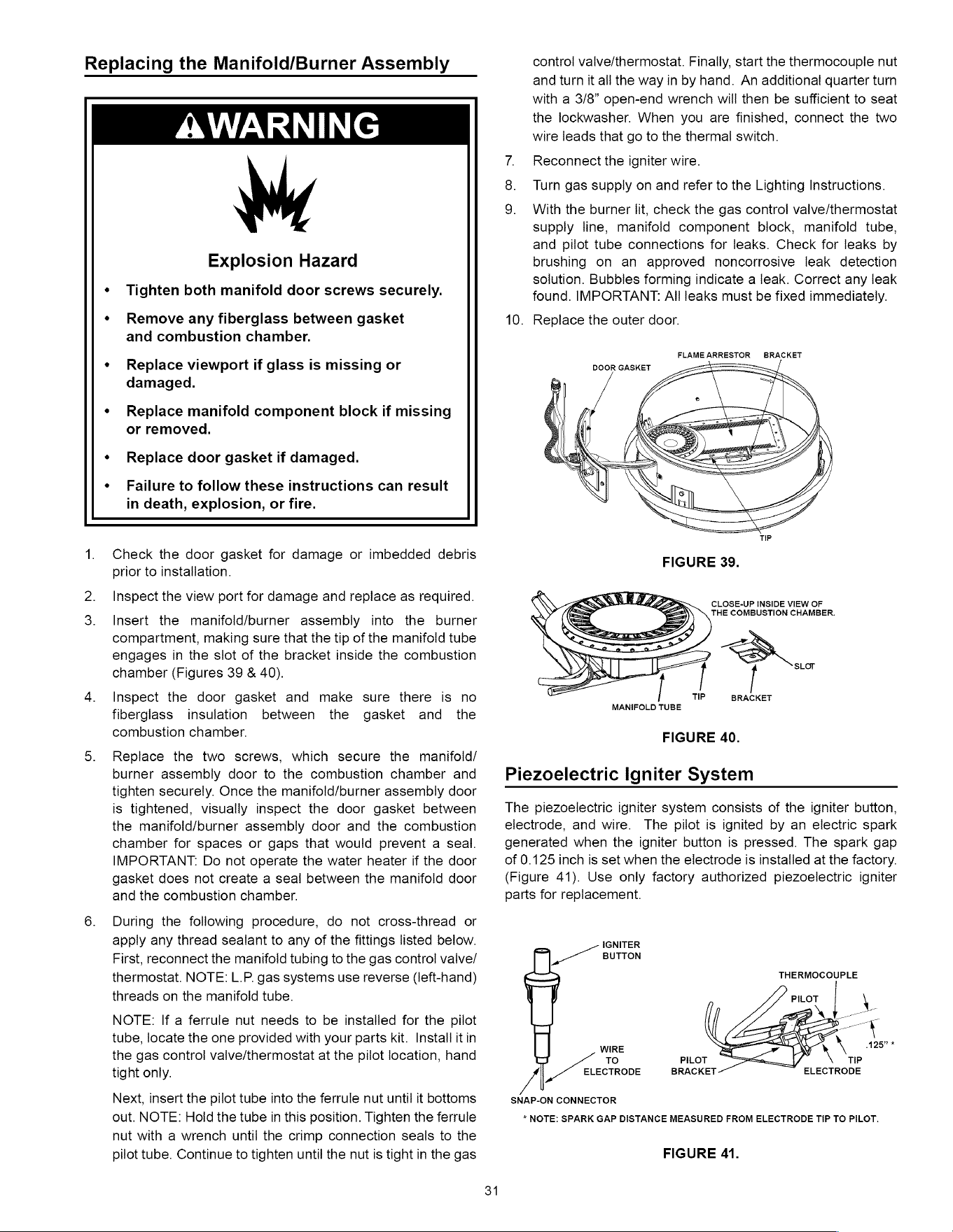
Replacing
the
Manifold/Burner
Assembly
AWARNING
Explosion
Hazard
¢
Tighten
both
manifold
door
screws
securely.
«
Remove
any
fiberglass
between
gasket
and
combustion
chamber.
«
Replace
viewport
if
glass
is
missing
or
damaged.
«
Replace
manifold
component
block
if
missing
or
removed.
¢
Replace
door
gasket
if
damaged.
¢«
Failure
to
follow
these
instructions
can
result
in
death,
explosion,
or
fire.
1.
Check
the
door
gasket
for
damage
or
imbedded
debris
prior
to
installation.
Inspect
the
view
port
for
damage
and
replace
as
required.
Insert
the
manifold/ourner
assembly
into
the
burner
compartment,
making
sure
that
the
tip
of
the
manifold
tube
engages
in
the
slot
of
the
bracket
inside
the
combustion
chamber
(Figures
39
&
40).
4.
Inspect
the
door
gasket
and
make
sure there
is
no
fiberglass
insulation
between
the
gasket
and
the
combustion
chamber.
5.
Replace
the
two
screws,
which
secure
the
manifoid/
burner
assembly
door
to
the
combustion
chamber
and
tighten
securely.
Once
the
manifold/burner
assembly
door
is
tightened,
visually
inspect
the
door
gasket
between
the
manifold/burner
assembly
door
and
the
combustion
chamber
for
spaces
or
gaps
that
would
prevent
a
seal.
IMPORTANT.
Do
not
operate
the
water
heater
if
the
door
gasket
does
not
create
a
seal
between
the
manifold
door
and
the
combustion
chamber.
6.
During
the
following
procedure,
do
not
cross-thread
or
apply
any
thread
sealant
to
any
of
the
fittings
listed
below.
First,
reconnect
the
manifold
tubing
to
the
gas
control
vaive/
thermostat.
NOTE:
L.P.
gas
systems
use
reverse
(left-hand)
threads
on
the
manifold
tube.
NOTE:
If
a
ferrule
nut
needs
to
be
installed
for
the
pilot
tube,
locate
the
one
provided
with
your
parts
kit.
Install
it
in
the
gas
control
valve/thermostat
at
the
pilot
location,
hand
tight
only.
Next,
insert
the
pilot
tube
into
the
ferrule
nut
until
it
bottoms
out.
NOTE:
Hold
the
tube
in
this
position.
Tighten
the
ferrule
nut
with
a
wrench
until
the
crimp
connection
seals
to
the
pilot
tube.
Continue
to
tighten
until
the nut
is
tight
in
the
gas
31
control
valve/thermostat.
Finally,
start
the
thermocouple
nut
and
turn
it
all
the
way
in
by
hand.
An
additional
quarter
turn
with
a
3/8”
open-end
wrench
will
then
be
sufficient
to
seat
the
lockwasher.
When
you
are
finished,
connect
the
two
wire
leads
that
go
to
the
thermal
switch.
7.
Reconnect
the igniter
wire.
Turn
gas
supply
on
and
refer
to
the
Lighting
Instructions.
9.
With
the
burner
lit,
check
the
gas
control
valve/thermostat
supply
line,
manifold
component
block,
manifold
tube,
and
pilot
tube
connections
for
leaks.
Check
for
leaks
by
brushing
on
an
approved
noncorrosive
leak
detection
solution.
Bubbles
forming
indicate
a
leak.
Correct
any
leak
found.
IMPORTANT:
All
leaks
must
be
fixed
immediately.
10.
Replace
the
outer
door.
FLAME
ARRESTOR
BRACKET
CLOSE-UP
INSIDE
VIEW
OF
THE
COMBUSTION
CHAMBER.
TIP
BRACKET
MANIFOLD
TUBE
FIGURE
40.
Piezoelectric
Igniter
System
The
piezoelectric
igniter
system
consisis
of
the
igniter
button,
electrode,
and
wire.
The
pilot
is
ignited
by an
electric
spark
generated
when
the
igniter
button
is
pressed.
The
spark
gap
of
0.125
inch
is
set
when
the
electrode
is
installed
at
the
factory.
(Figure
41).
Use
only
factory
authorized
piezoelectric
igniter
parts
for
replacement.
IGNITER
~——
BUTTON
THERMOCOUPLE
WIRE
TO
/
ELECTRODE
SNAP-ON
CONNECTOR
TIP
ELECTRODE
*
NOTE:
SPARK
GAP
DISTANCE
MEASURED
FROM
ELECTRODE
TIP
TO
PILOT.
FIGURE
41.
Testing
the
Igniter
System
Turn
off
the
gas
to
the
water
heater
at
the
manual
gas
shut-off
valve.
Watch
the
electrode
tip
while
activating
the
igniter.
A
visible
spark
should
jump
from
the
electrode.
To
avoid
shock,
do
not
touch
the
burner
or
any
metal
part
on
the
pilot or
pilot
assembly.
If
no
spark
is
visible,
check
the
wire
connections
and
make
sure
the
electrode
is
not
broken.
Replace
the
igniter
if
defective.
Dirt
and
rust
on
the
pilot
or
electrode
tip
can
prevent
the
igniter
spark.
Wipe
clean
with
a
damp
cloth
and
dry
completely.
Rust
can
be
removed
from
the
electrode
tip
and
metal
surfaces
by
lightly
sanding
with
an
emery
cloth
or
fine
grit
sandpaper.
Removing
and
Replacing
the
Gas
Control
Valve/Thermostat
IMPORTANT:
This
water
heater
has
a
resettable
thermal
switch
installed.
Do
not
attempt
to
disable
or
modify
this
feature
in
any
way.
Use
only
factory
authorized
replacement
parts.
Removing
the
Gas
Valve:
1.
Turn
off
the
gas
supply
to
the
water
heater
at
the
manual
gas
shut-off
valve.
This
valve
is
typically
located
beside
the
water
heater.
Note
the
position
of
the
shut-off
valve
in
the
open/on
position
then
proceed
to
turn
it
off
(Figure
11).
On
the
lower
front
of
the
water
heater,
locate
the
gas
control
valve/thermostat
(see
Figure
32).
Before
performing
any
maintenance,
it
is
important
to
turn
the
temperature
dial
on
the
gas
control
valve/thermostat
to
its
lowest
setting.
3.
On
top
of
the
gas
control
valve/thermositat,
turn
the
gas
control
knob
to
the
“OFF”
position.
See
Lighting
Instructions
on
the
water
heater.
Drain
the
water
heater.
Refer
to
the
section
of
“Draining
and
Flushing”
section
and
follow
the
procedure.
5.
Disconnect
the
igniter
wire
from
the
igniter.
NOTE:
There
are
two
types
of
igniters.
If
you
have
the
square
igniter,
slide the
igniter
bracket
backwards
away
from
the
gas
valve
to
remove
it.
If
you
have
the
round
igniter,
first
remove
the
igniter
from
the
bracket
by
depressing
front
and
rear
holding
tabs
and
lift.
Next,
remove
the
igniter
bracket
from
the
gas
valve.
Disconnect
the
thermocouple
(right-hand
threads),
pilot
tube,
and
manifold
tube
at
the
gas
control
valve/thermostat
(Figure
31).
NOTE:
L.P.
gas
systems
use
reverse
(left-hand)
threads
on
the
manifold
tube.
Also,
disconnect
the
thermal
switch
wires.
Refer
to
“Gas
Piping”
section
(Figure
11)
and
disconnect
the
ground
joint
union
in
the
gas
piping.
Disconnect
the
remaining
pipe
from
the
gas
control
valve/thermostat.
7.
To
remove
the
gas
control
valve/thermosiat,
thread
a
correctly
sized
pipe
into
the
inlet
and
use
it
to
turn
the
gas
control
valve/thermostat
(counterclockwise.)
Do
not
use
a
pipe
wrench
or
equivalent
to
grip
body.
Damage
may
result,
causing
leaks.
Donotinsert
any
sharp
objects
into
the
inlet
or
outlet
connections.
Damage
to
the
gas
control
valve/thermostat
may
result.
Replacing
the
Gas
Valve:
1.
To
replace
the
gas
control
valve/thermostat,
reassemble
in
reverse
order.
When
replacing
the
gas
control
valve/
thermosiat,
thread
a
correctly
sized
pipe
into
the
inlet
and
use
it
to
turn
the
gas
valve
(clockwise.)
DO
NOT
OVER
TIGHTEN
or
damage
may
result.
NOTE:
Use
an
approved
TEFLON®
tape
or
pipe
compound
only
on
the
threaded
section
of
the
gas
control
valve/thermostat
that
screws
into
the
tank.
32
Reconnect
the
gas
piping
to
the
gas
control
valve/
thermostat.
NOTE:
Use
an
approved
Teflon
tape
or
pipe
compound
on
the
gas
piping
connections.
3.
Attach
the
igniter
and
bracket
to
the
new
gas
controi
valve/
thermostat,
clipping
it
at
the
back
edge
of
thermostat
and
snapping
it
into
place.
NOTE:
Do
not
use
the
(pilot)
ferrule
nut
supplied
with
the
new
gas
control
valve/thermostat,
unless
the
existing
nut
is
not
usable.
Reconnect
the
pilot
tube,
manifold
tube,
thermocouple,
igniter
wire,
and
thermal
switch
wires.
NOTE:
L.P.
gas
systems
use
reverse
(left-
hand)
threads
on
the
manifold
tube.
Fill
the
tank
completely
with
water.
NOTE:
To
purge
the
lines
of
any
excess
air,
keep
the hot
water
faucet
open
for
3
minutes
after
a
constant
flow
of
water
is
obtained.
5.
Turn
onthe
gas
supply
and
test
the
gas
supply
connections
by
brushing
on
an
approved
noncorrosive
leak
detection
solution.
Bubbles
forming
indicate
a
leak.
Correct
any
leak
found.
Check
the
operation
of
the
burner
by
following
the
lighting
instructions
on
the
front
of
the
water
heater.
With
the
burner
lit,
check
the
gas
control
valve/thermostat
supply
line,
manifold
tube
and
pilot
tube
connections
for
leaks.
7.
Verify
proper
operation
and
then
replace
the
outer
door.
8.
If
additional
information
is
required,
contact Residential
Technical
Assistance
by
referencing
the
number
on
the
water
heater.
TEFLON®
is
a
registered
trademark
of
E.|.
Du
Pont De
Nemours
and
Company.
FVIR
System
Operational
Checklist
Manifold
gasket
properly
sealed.
Viewport
not
damaged
or
cracked.
Flame-arrestor
free
of
debris
and
undamaged.
Manifold
component
block
properly
installed.
No
leaks
at
pilot
and
manifold
connection.
Manifold
door
screws
securely
tightened.
NOG
oO PF
WN
>
Depress
the
button
on
the
thermal
switch.
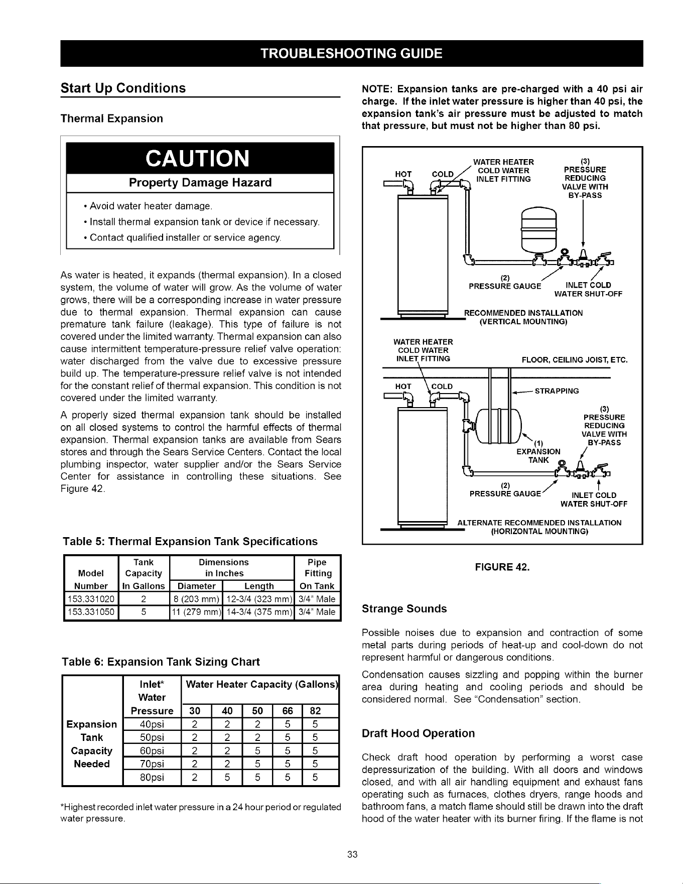
TROUBLESHOOTING
GUIDE
Start
Up
Conditions
Thermal
Expansion
CAUTION
Property
Damage
Hazard
¢
Avoid
water
heater
damage.
¢
Install
thermal
expansion
tank
or
device
if
necessary.
¢
Contact
qualified
installer
or
service
agency.
As
water
is
heated,
it
expands
(thermal
expansion).
In
a
closed
system,
the
volume
of
water
will
grow.
As
the
volume
of
water
grows,
there
will
be
a
corresponding
increase
in
water
pressure
due
to
thermal
expansion.
Thermal
expansion
can
cause
premature
tank
failure
(leakage).
This
type
of
failure
is
not
covered
under
the
limited
warranty.
Thermal
expansion
can
also
cause
intermittent
temperature-pressure
relief
valve
operation:
water
discharged
from
the
valve
due
to
excessive
pressure
build
up.
The
temperature-pressure
relief
valve
is
not
intended
for
the
constant
relief
of
thermal
expansion.
This
condition
is
not
covered
under
the
limited
warranty.
A
properly
sized
thermal
expansion
tank
should
be
installed
on
all
closed
systems
to
control
the
harmful
effects
of
thermal
expansion.
Thermal
expansion
tanks
are
available
from
Sears
stores
and
through
the
Sears
Service Centers.
Contact
the
local
plumbing
inspector,
water
supplier
and/or
the
Sears
Service
Center
for
assistance
in
controlling
these
situations.
See
Figure
42.
Table
5:
Thermal
Expansion
Tank
Specifications
Tank
Dimensions
Pipe
Model
Capacity
in
Inches
Fitting
Number
[In
Gallons
|
Diameter
Length
On
Tank
153.331020
2
8
(203
mm)
|
12-3/4
(323
mm)]
3/4”
Male
153.331050
5
11
(279 mm)}
14-3/4
(375
mm)|
3/4”
Male
Table
6:
Expansion
Tank
Sizing
Chart
Inlet*
Water
Heater
Capacity
(Gallons
Water
Pressure
|
30 40 50 66
|
82
Expansion
40psi
2 2 2
5 5
Tank
50psi
2 2 2
5 5
Capacity
60psi
2 2
5 5 5
Needed
70psi
2 2
5 5 5
80psi
2
5 5 5 5
*Highest
recorded
inlet
water
pressure
in
a
24
hour
period
or
regulated
water
pressure.
NOTE:
Expansion
tanks
are
pre-charged
with
a
40
psi
air
charge.
If
the
inlet
water
pressure
is
higher
than
40
psi,
the
expansion
tank’s
air
pressure
must
be
adjusted
to
match
that
pressure,
but
must
not
be
higher
than
80
psi.
WATER
HEATER
(3)
COLD
WATER
PRESSURE
ROT
SPLO
4
INLET FITTING
REDUCING
ct)
VALVE
WITH
BY-PASS
@)
Va
/-
PRESSURE
GAUGE
INLET
COLD
WATER
SHUT-OFF
RECOMMENDED
INSTALLATION
es
——_WERTICAL
MOUNTING)
WATER
HEATER
COLD
WATER
INLET
FITTING
FLOOR,
CEILING
JOIST,
ETC.
\
.«-—-——
STRAPPING
(3)
PRESSURE
REDUCING
|
VALVE
WITH
(1)
BY-PASS
EXPANSION
TANK
PobagS
2)
YY
PRESSURE
GAUGE
INLET
COLD
WATER
SHUT-OFF
ALTERNATE
RECOMMENDED
INSTALLATION
On
(HORIZONTAL
MOUNTING)
FIGURE
42.
Strange
Sounds
Possible
noises
due
to
expansion
and
contraction
of
some
metal
parts
during
periods
of
heat-up
and
cool-down
do
not
represent
harmful
or
dangerous
conditions.
Condensation
causes
sizzling
and
popping
within
the
burner
area
during
heating
and cooling
periods
and
should
be
considered
normal.
See
“Condensation”
section.
Draft
Hood
Operation
Check
draft
hood
operation
by
performing
a
worst
case
depressurization
of
the
building.
With
all
doors
and
windows
closed,
and
with
all
air
handling
equipment
and
exhaust
fans
operating
such
as
furnaces,
clothes
dryers,
range
hoods
and
bathroom
fans,
a
match
flame
should
still
be
drawn
into
the
draft
hood
of
the
water
heater
with
its
burner
firing.
If
the
flame
is
not
drawn
toward
the
draft
hood,
shut
off
water
heater
and
make
necessary
air
supply
changes
to
correct.
Condensation
Whenever
the
water
heater
is
filled
with
cold
water,
some
condensate
will
form
while
the
burner
is
on.
A
water
heater
may
appear
to
be
leaking
when
in
fact
the
water
is
condensation.
This
usually
happens
when:
«
A
new
water
heater
is
filled
with
cold
water
for
the
first
time.
«
Burning
gas
produces
water
vapor
In
water
heaters,
particularly
high
efficiency
models
where
flue
temperatures
are
lower.
«
Large
amounts
of
hot
water
are
used
in
a
short
time
and
the
refill
water
in
the
tank
is
very
cold.
Moisture
from
the
products
of
combustion
condense
on
the
cooler
tank
surfaces
and
form
drops
of
water
which
may
fall
onto
the
burner
or
other
hot
surfaces
to
produce
a
“sizzling”
or
“frying”
noise.
Excessive
condensation
can
cause
pilot
outage
due
to
water
running
down
the
flue
tube
onto
the
main
burner
and
putting
out
the
pilot.
Because
of
the
suddenness
and
amount
of
water,
condensation
water
may
be
diagnosed
as
a
“tank
leak”.
After
the
water
in
the
tank
warms
up
(about
1-2
hours),
the
condition
should
disappear.
Do
not
assume
the
water
heater
is
leaking
until
there
has
been
enough
time
for
the
water
in
the
tank
to
warm
up.
An
undersized
water
heater
will
cause
more
condensation.
The
water
heater
must
be
sized
properly
to
meet
the
family’s
demands
for
hot
water
including
dishwashers,
washing
machines
and
shower
heads.
Excessive
condensation
may
be
noticed
during
the
winter
and
early
spring
months
when
incoming
water
temperatures
are
at
their
lowest.
Good
venting
is
essential
for
a
gas
fired
water
heater
to
operate
properly
as
well
as
to
carry
away
products
of
combustion
and
water
vapor.
Smoke
Odor
It
is
not
uncommon
to
experience
a
small
amount
of
smoke
and
odor
during
the
initial
start-up.
This
is
due
to
burning
off
of
oil
from
metal
parts,
and
will
disappear
in
a
short
while.
Operational
Conditions
Smelly
Odor
In
each
water
heater
there
is
installed
at
least
one
anode
rod
(see
parts
section)
for
corrosion
protection
of
the
tank.
Certain
water
conditions
will
cause
a
reaction
between
this
rod
and
the
water.
The
most
common
complaint
associated
with
the
anode
rod
is
one
of
a
“rotten
egg
smell’.
This
odor
is
derived
from
hydrogen
sulfide
gas
dissolved
in
the
water.
The
smell
is
the
34
result
of
four
factors
which
must
all
be
present
for
the
odor
to
develop:
*
aconcentration
of
sulfate
in
the
supply
water.
+
little
or
no
dissolved
oxygen
in
the
water.
«
a
sulfate
reducing
bacteria
within
the
water
heater.
(This
harmless
bacteria
is
non-toxic
to
humans.)
*
an
excess
of
active
hydrogen
in
the
tank.
This
is
caused
by
the
corrosion
protective
action
of
the
anode.
Smelly
water
may
be
eliminated
or
reduced
in
some
water
heater
models
by
replacing
the
anode(s)
with
one
of
less
active
material,
and
then
chlorinating
the
water
heater
tank
and
all
hot
water
lines.
Contact
Sears
Service
for
further
information
concerning
this
chlorination
treatment
and
an
anode
replacement
kit
#9001453.
(For
short
heaters,
use
anode
replacement
kit
#9006299.)
Anode
replacement
and
chlorination
of
the
tank
are
not
covered
by
the
water
heater’s
limited
warranty.
If
the
smelly
water
persists
after
the
anode
replacement
and
chlorination
treatment,
it
may
be
necessary
to
chlorinate
or
aerate
your
water
supply
to
eliminate
the
problem.
Do
not
remove
the
anode,
leaving
the
tank
unprotected.
By
doing
so,
all
warranty
on
the
water
heater
tank
is
voided.
“AIR”
In
Hot
Water
Faucets
A
WARNING
Explosion
Hazard
*
Flammable
hydrogen
gases
may
be
present.
¢
Keep
all
ignition
sources
away
from
faucet
when
turning
on
hot
water.
HYDROGEN
GAS:
Hydrogen
gas
can
be
produced
in
a
hot
water
system
that
has
not
been
used
for
a
long
period
of
time
(generally
two
weeks
or
more).
Hydrogen
gas
is
extremely
flammable
and
explosive.
To
prevent
the
possibility
of
injury
under
these
conditions,
we
recommend
the hot
water
faucet,
located
farthest
away,
be
opened
for
several
minutes
before
any
electrical
appliances
which
are
connected
to
the hot
water
system
are
used
(such
as
a
dishwasher
or
washing
machine).
If
hydrogen
gas
is
present,
there
will
probably
be an
unusual
sound
similar
to
air
escaping
through
the
pipe
as
the
hot
water
faucet
is
opened.
There
must
be no
smoking
or
open
flame
near
the
faucet
at
the
time
it
is
open.
Safety
Shut-off
and
Thermal
Switch
This
water
heater
is
designed
to
automatically
shut-off
in
the
event
of
the
following:
1.
The
pilot
flame
is
extinguished
for
any
reason.
2.
The
water
temperature
exceeds
195°F
(91°C).
3.
Excessive
build
up
of
dust
on
the
base
ring
filter
or
flame
arrestor.
See
Maintenance
of
your
Water
Heater
Section.
4.
The
ignition
of
flammable
vapors.
A
thermocouple
is
used
to
determine
if
a
pilot
flame
is
present,
and
will
shut
off
the
gas
supply
to
the
main
burner
and
the
pilot
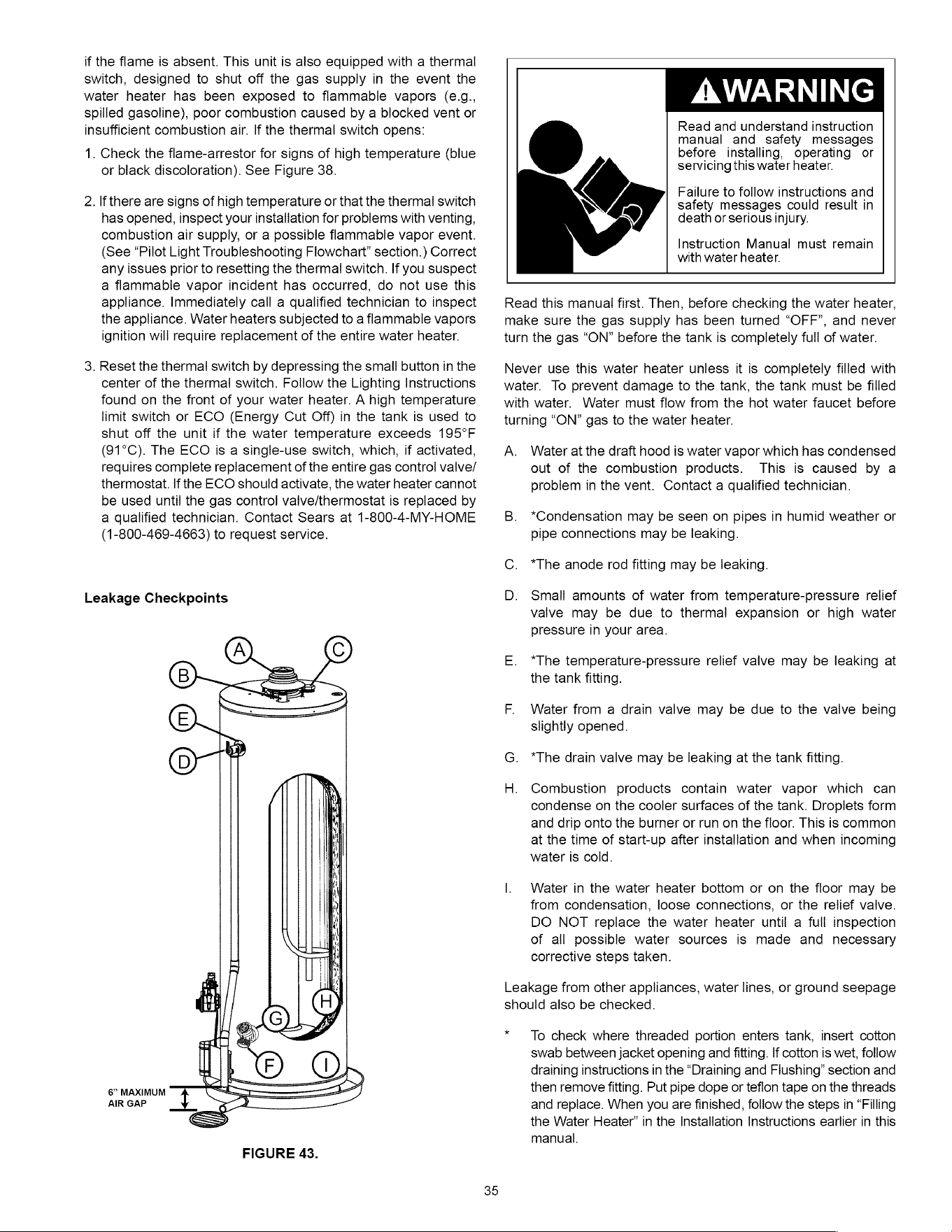
if
the
flame
is
absent.
This
unit
is
also
equipped
with
a
thermal
switch,
designed
to
shut
off
the
gas
supply
in
the
event
the
water
heater
has
been
exposed
to
flammable
vapors
(e.g.,
spilled
gasoline),
poor
combustion
caused
by
a
blocked
vent
or
insufficient
combustion
air.
If
the
thermal
switch
opens:
1.
Check
the
flame-arrestor
for
signs
of
high
temperature
(blue
or
black
discoloration).
See
Figure
38.
2.
lf
there
are
signs
of
high
temperature
or
that
the
thermal
switch
has
opened,
inspect
your
installation
for
problems
with
venting,
combustion
air
supply,
or
a
possible
flammable
vapor
event.
(See
“Pilot
Light
Troubleshooting
Flowchart”
section.)
Correct
any
issues
prior
to
resetting
the
thermal
switch.
If
you
suspect
a
flammable
vapor
incident
has
occurred,
do
not
use
this
appliance.
Immediately
call
a
qualified
technician
to
inspect
the
appliance.
Water
heaters
subjected
to
a
flammable
vapors
ignition
will
require
replacement
of
the
entire
water
heater.
3.
Reset
the
thermal
switch
by
depressing
the
small
button
in
the
center
of
the
thermal
switch.
Follow
the
Lighting
Instructions
found
on
the
front
of
your
water
heater.
A
high
temperature
limit
switch
or
ECO
(Energy
Cut
Off)
in
the
tank
is
used
to
shut
off
the
unit
if
the
water
temperature
exceeds
195°F
(91°C).
The
ECO
is
a
single-use
switch,
which,
if
activated,
requires
complete
replacement
of
the
entire
gas
control
valve/
thermostat.
If
the
ECO
should
activate,
the
water
heater
cannot
be
used
until
the
gas
control
valve/thermostat
is
replaced
by
a
qualified
technician.
Contact
Sears
at
1-800-4-MY-HOME
(1-800-469-4663)
to
request
service.
Leakage
Checkpoints
8”
MAXIMUM
AIR
GAP
FIGURE
43.
35
AWARNING
Read
and
understand
instruction
manual
and
safety
messages
before
installing,
operating
or
servicing
this
water
heater.
Failure
to
follow
instructions
and
safety
messages
could
result
in
death
or
serious
injury.
Instruction
Manual
must
remain
with
water
heater.
Read
this
manual
first.
Then,
before
checking
the
water
heater,
make
sure
the
gas
supply
has
been
turned
“OFF”,
and
never
turn
the
gas
“ON”
before
the
tank
is
completely
full
of
water.
Never
use
this
water
heater
unless
it
is
completely
filled
with
water.
To
prevent
damage
to
the
tank,
the
tank
must
be
filled
with
water.
Water
must
flow
from
the hot
water
faucet before
turning
“ON”
gas
to
the
water
heater.
A.
Water
at
the
draft
hood
is
water
vapor which
has
condensed
out
of
the
combustion
products.
This
is
caused
by
a
problem
in
the
vent.
Contact
a
qualified
technician.
B.
*Condensation
may
be
seen
on
pipes
in
humid
weather
or
pipe
connections
may
be
leaking.
C.
*The
anode
rod
fitting
may
be
leaking.
D.
Small
amounts
of
water
from
temperature-pressure
relief
valve
may
be
due
to
thermal
expansion
or
high
water
pressure
in
your
area.
E.
*The
temperature-pressure
relief
valve
may
be
leaking
at
the
tank
fitting.
F.
Water
from
a
drain
valve
may
be
due
to
the
valve
being
slightly
opened.
*The
drain
valve
may
be
leaking
at
the
tank
fitting.
Combustion
products
contain
water
vapor which
can
condense
on
the
cooler
surfaces
of
the
tank.
Droplets
form
and
drip
onto
the
burner
or
run
on
the
floor.
This
is
common
at
the
time
of
start-up
after
installation
and
when
incoming
water
is
cold.
|.
Water
in
the
water
heater
bottom
or
on
the
floor
may
be
from
condensation,
loose
connections,
or
the
relief
valve.
DO
NOT
replace
the
water
heater
until
a
full
inspection
of
all
possible
water
sources
is
made
and
necessary
corrective
steps
taken.
Leakage
from
other
appliances,
water
lines,
or
ground
seepage
should
also
be
checked.
*
To
check
where
threaded
portion
enters
tank,
insert
cotton
swab
between
jacket
opening
and
fitting.
If
cotton
is
wet,
follow
draining
instructions
in
the
“Draining
and
Flushing”
section
and
then
remove
fitting.
Put
pipe
dope
or
teflon
tape
on
the
threads
and
replace.
When
you
are
finished,
follow
the
steps
in
“Filling
the
Water
Heater”
in
the
Installation
Instructions
earlier
in
this
manual.
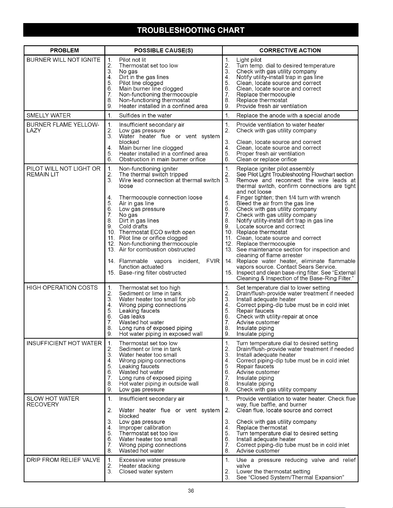
TROUBLESHOOTING
CHART
PROBLEM
POSSIBLE
CAUSE(S)
CORRECTIVE
ACTION
BURNER
WILL
NOT
IGNITE
|
1.
Pilot
not
lit
1.
Light
pilot
2.
Thermostat
set
too
low
2.
Turn
temp.
dial
to
desired
temperature
3.
Nogas
3.
Check
with
gas
utility
company
4.
Dirtin
the
gas
lines
4.
Notify
utility-install
trap
in
gas
line
5.
Pilot
line
clogged
5.
Clean,
locate
source
and correct
6.
Main
burner
line
clogged
6.
Clean,
locate
source
and
correct
7.
Non-functioning
thermocouple
7.
Replace
thermocouple
8.
Non-functioning
thermostat
8.
Replace
thermostat
9.
Heater
installed
in
a
confined
area
9.
Provide
fresh
air
ventilation
SMELLY
WATER
1.
Sulfides
in
the
water
1.
Replace
the
anode
with
a
special
anode
BURNER
FLAME
YELLOW-
|
1.
_
Insufficient
secondary
air
1.
Provide
ventilation
to
water
heater
LAZY
2.
Low
gas
pressure
2.
Check
with
gas
utility
company
3.
Water
heater
flue
or
vent
system
blocked
3.
Clean,
locate
source
and correct
4.
Main
burner
line
clogged
4.
Clean,
locate
source
and
correct
5.
Heater
installed
in
a
confined
area
5.
Proper
fresh
air
ventilation
6.
Obstruction
in
main
burner
orifice
6.
Clean
or
replace
orifice
PILOT
WILL
NOT
LIGHT OR
|
1.
Non-functioning
igniter
1.
Replace
igniter
pilot
assembly
REMAIN
LIT
2.
The thermal
switch
tripped
2.
See
Pilot
Light
Troubleshooting
Flowchart
section
3.
Wire
lead
connection
at
thermal
switch
|
3.
Remove
and
reconnect
the
wire
leads
at
loose
thermal
switch,
confirm
connections
are
tight
and
not
loose
4.
Thermocouple
connection
loose
4.
Finger
tighten;
then
1/4
turn
with
wrench
5.
Aijrin
gas
line
5.
Bleed
the
air
from
the
gas
line
6.
Low
gas
pressure
6.
Check
with
gas
utility
company
7.
Nogas
7.
Check
with
gas
utility
company
8.
Dirt
in
gas
lines
8.
Notify
utility-install
dirt
trap
in
gas
line
9.
Cold
drafts
9.
Locate
source
and
correct
10.
Thermostat
ECO
switch
open
10.
Replace
thermostat
11.
Pilot
line
or
orifice
clogged
11.
Clean,
locate
source
and
correct
12.
Non-functioning
thermocouple
12.
Replace
thermocouple
13.
Air
for
combustion
obstructed
13.
See
maintenance
section
for
inspection
and
cleaning
of
flame
arrester
14.
Flammable
vapors
incident,
FVIR|14.
Replace
water
heater,
eliminate
flammable
function
actuated
vapors
source.
Contact
Sears
Service.
15.
Base-ring
filter
obstructed
15.
Inspect
and
clean
base-ring
filter.
See
“External
Cleaning
&
Inspection
of
the
Base-Ring
Filter.”
HIGH
OPERATION
COSTS
1.
Thermostat
set
too
high
1.
Set
temperature
dial
to
lower
setting
2.
Sediment
or
lime
in
tank
2.
Drain/flush-provide
water
treatment
if
needed
3.
Water
heater
too
smail
for
job
3.
Install
adequate
heater
4.
Wrong
piping
connections
4.
Correct
piping-dip
tube
must
be
in
cold
inlet
5.
Leaking
faucets
5.
Repair
faucets
6.
Gas
leaks
6.
Check
with
utility-repair
at
once
7.
Wasted
hot
water
7.
Advise
customer
8.
Long
runs
of
exposed
piping
8.
Insulate
piping
9.
Hot
water
piping
in
exposed
wall
9.
Insulate
piping
INSUFFICIENT
HOT
WATER
|
1.
Thermostat
set
too
low
1.
Turn
temperature
dial
to
desired
setting
2.
Sediment
or
lime
in
tank
2.
Drain/flush-provide
water
treatment
if
needed
3.
Water
heater
too
small
3.
Install
adequate
heater
4.
Wrong
piping
connections
4.
Correct
piping-dip
tube
must
be
in
cold
inlet
5.
Leaking
faucets
5
Repair
faucets
6.
Wasted
hot
water
6.
Advise
customer
7.
Long
runs
of
exposed
piping
7.
Insulate
piping
8.
Hot
water
piping
in
outside
wall
8.
Insulate
piping
9.
Low
gas
pressure
9.
Check
with
gas
utility
company
SLOW
HOT
WATER
1.
Insufficient
secondary
air
1.
Provide
ventilation
to
water
heater.
Check
flue
RECOVERY
way,
flue
baffle,
and
burner
2.
Water
heater
flue
or
vent
system]|2.
Clean
flue,
locate
source
and correct
blocked
3.
Low
gas
pressure
3.
Check
with
gas
utility
company
4.
Improper
calibration
4.
Replace
thermostat
5.
Thermostat
set
too
low
5.
Turn
temperature
dial
to
desired
setting
6.
Water
heater
too
small
6.
Install
adequate
heater
7.
Wrong
piping
connections
7.
Correct
piping-dip
tube
must
be
in
cold
inlet
8.
Wasted
hot
water
8.
Advise
customer
DRIP
FROM
RELIEF
VALVE
|
1.
Excessive
water
pressure
1.
Use
a
pressure
reducing
valve
and
relief
2.
Heater
stacking
valve
3.
Closed
water
system
2.
Lower
the
thermostat
setting
3.
See “Closed
System/Thermal
Expansion”
36
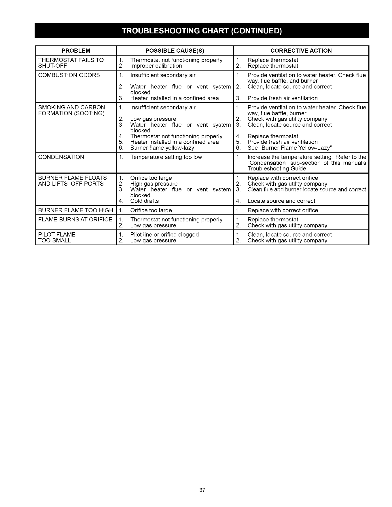
TROUBLESHOOTING
CHART
(CONTINUED)
PROBLEM
POSSIBLE
CAUSE(S)
CORRECTIVE
ACTION
THERMOSTAT
FAILS
TO
1.
Thermostat
not
functioning
properly
1.
Replace
thermostat
SHUT-OFF
2.
Improper
calibration
2.
Replace
thermostat
COMBUSTION
ODORS
1.
Insufficient
secondary
air
1.
Provide
ventilation
to
water
heater.
Check
flue
way,
flue
baffle,
and
burner
2.
Water
heater
flue
or
vent
system]|2.
Clean,
locate
source
and
correct
blocked
3.
Heater
installed
in
a
confined
area
3.
Provide
fresh
air
ventilation
SMOKING
AND
CARBON
1.
Insufficient
secondary
air
1.
Provide
ventilation
to
water
heater.
Check
flue
FORMATION
(SOOTING)
way,
flue
baffle,
burner
2.
Low
gas
pressure
2.
Check
with
gas
utility
company
3.
Water
heater
flue
or
vent
system]3.
Clean,
locate
source
and
correct
blocked
4.
Thermostat
not
functioning
properly
4.
Replace
thermostat
5.
Heater
installed
in
a
confined
area
5.
Provide
fresh
air
ventilation
6.
Burner
flame
yellow-lazy
6.
See “Burner
Flame
Yellow-Lazy”
CONDENSATION
1.
Temperature
setting
too
low
1.
Increase
the
temperature
setting.
Refer
to
the
“Condensation”
sub-section
of
this
manual’s
Troubleshooting
Guide.
BURNER
FLAME
FLOATS
1.
Orifice
too
large
1.
Replace
with
correct
orifice
AND
LIFTS
OFF
PORTS
2.
High
gas
pressure
2.
Check
with
gas
utility
company
3.
Water
heater
flue
or
vent
system]3.
Clean
flue
and
burner-locate
source
and
correct
blocked
4.
Cold
drafts
4.
Locate
source
and correct
BURNER
FLAME
TOO
HIGH
|
1.
Orifice
too
large
1.
Replace
with
correct
orifice
FLAME
BURNS
AT
ORIFICE
|
1.
Thermostat
not
functioning
properly
1.
Replace
thermostat
2.
Low
gas
pressure
2.
Check
with
gas
utility
company
PILOT
FLAME
1.
Pilot
line
or
orifice
clogged
1.
Clean,
locate
source
and
correct
TOO
SMALL
2.
Low
gas
pressure
2.
Check
with
gas
utility
company
37
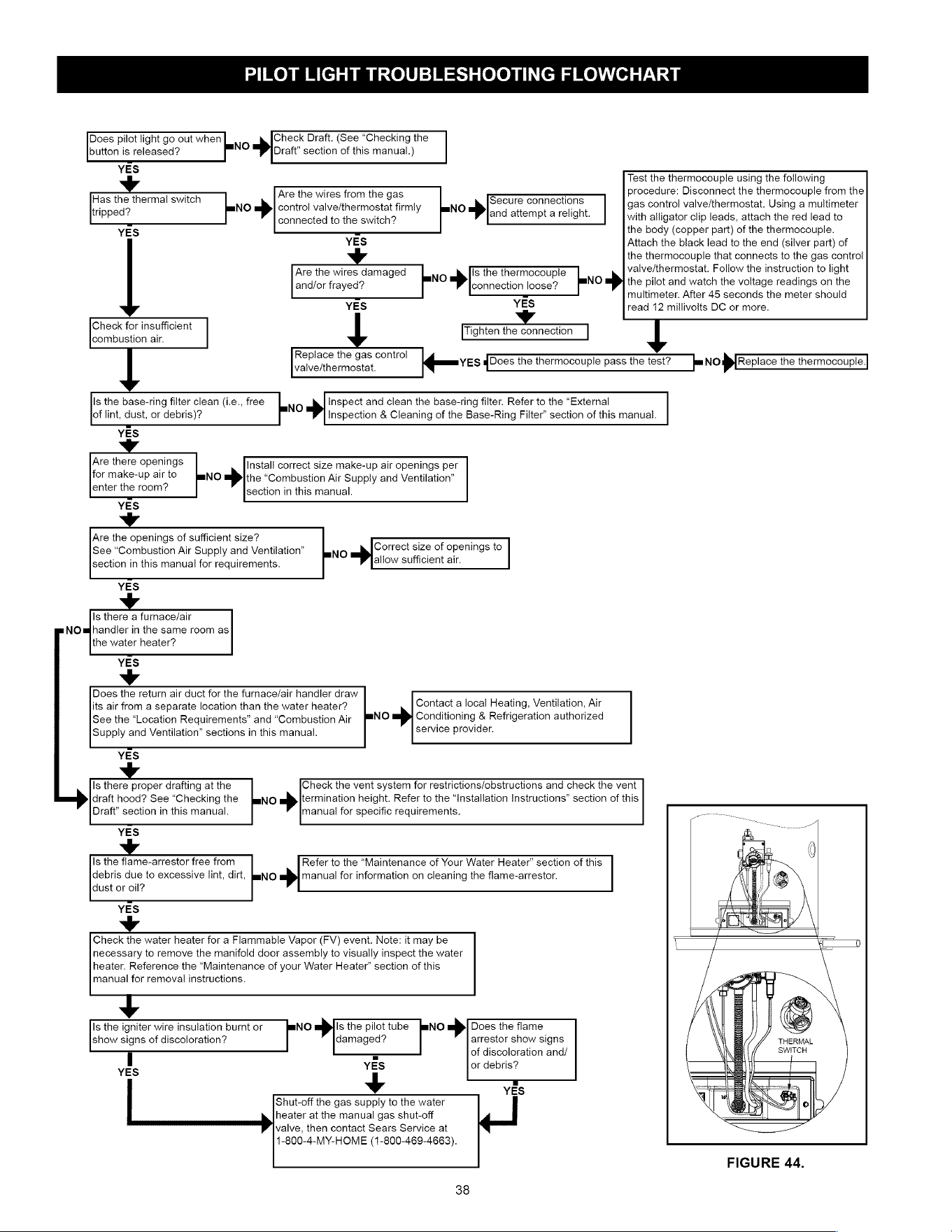
PILOT
LIGHT
TROUBLESHOOTING
FLOWCHART
Does
pilot
light
go
out
when
Check
Draft.
(See
“Checking
the
button
is
released?
NO
»>
Draft”
section
of
this
manual.)
YES
Fas
ihe
thermal
switch
No
»>
control
valve/thermostat
firmly
l_=NO
>»
secure
connections
gas
control
valve/thermostat.
Using
a
multimeter
ppeds
connected
to
the
switch?
ana
attempt
a
reilgnt.
with alligator
clip
leads,
attach
the red
lead
to
YES
the
body (copper
part)
of
the
thermocouple.
Are
the
wires from
the
gas
Test
the
thermocouple
using
the
following
procedure:
Disconnect
the
thermocouple
from
the
YES
v
Are
the
wires
damaged
and/or
frayed?
YES
Attach
the
black
lead
to
the
end
(silver
part)
of
the
thermocouple
that
connects
to
the
gas
control
valve/thermostat.
Follow
the
instruction
to
light
mNO
»>
the
pilot
and
watch
the
voltage
readings
on
the
multimeter.
After
45
seconds
the
meter
should
read
12
millivolts
DC
or
more.
LO
»>
Is
the
thermocouple
connection
loose?
YES
Tighten
the
connection
qamnves
qDoes
the
thermocouple
pass
the
test?
Check
for
insufficient
combustion
air.
Replace
the
gas
control
valve/thermostat.
ju
Nop
[Replace
the
thermocouple
|
Is
the
base-ring
filter
clean
(i.e.,
free
of
lint,
dust,
or
debris)?
YES
LENO
>|
Inspect and
clean
the
base-ring
filter.
Refer
to
the
“External
Inspection
&
Cleaning
of
the
Base-Ring
Filter’
section
of
this
manual.
Are
there
openings
for
make-up
air
to
enter
the
room?
YES
Vv
Are
the
openings
of
sufficient
size?
See
“Combustion
Air
Supply
and
Ventilation”
section
in
this
manual
for
requirements.
Install
correct
size
make-up
air
openings
per
the
“Combustion
Air
Supply
and
Ventilation”
NO
»>
section
in
this
manual.
Correct
size
of
openings
to
mNO
=»
allow
sufficient
air.
YES
Is
there
a
furnace/air
NOmbhandler
in
the
same
room
as
the
water
heater?
YES
v
Does
the
return
air
duct
for
the
furnace/air
handier
draw
its
air
from
a
separate
location
than
the
water
heater?
See
the
“Location
Requirements”
and
“Combustion
Air
Supply
and
Ventilation”
sections
in
this
manual.
Contact
a
local
Heating,
Ventilation,
Air
mNiO
=»
Conditioning
&
Refrigeration
authorized
service
provider.
YES
Is
there
proper
drafting
at
the
draft
hood?
See
“Checking
the
Draft”
section
in
this
manual.
YES
Check
the
vent
system
for
restrictions/obstructions
and
check
the
vent
NO
»>
termination
height.
Refer
to
the
“Installation
Instructions”
section
of
this
manual
for
specific
requirements.
Is
the
flame-arrestor
free
from
debris
due
to
excessive
lint,
dirt,
dust
or
oil?
Refer
to
the
“Maintenance
of
Your
Water
Heater”
section
of
this
manual
for
information
on
cleaning
the
flame-arrestor.
YES
Check
the
water
heater
for
a
Flammable
Vapor
(FV)
event.
Note:
it
may
be
necessary
to
remove
the
manifold
door
assembly
to
visually
inspect
the
water
heater.
Reference
the
“Maintenance
of
your
Water
Heater”
section
of
this
manual
for
removal
instructions.
v
Is
the
igniter
wire
insulation
burnt
or
mNO
»>
Is
the
pilot
tube
[mNO
»>
Does
the
flame
show
signs
of
discoloration?
damaged?
arrestor
show
signs
THERMAL
=
of
discoloration
and/
SWITCH
YES
or
debris?
if
|
YES
FIGURE
44.
v
Shut-off
the
gas
supply
to
the
water
heater
at
the
manual
gas
shut-off
valve,
then
contact
Sears
Service
at
1-800-4-MY-HOME
(1-800-469-4663).
¥
YES
38

NOTES
39
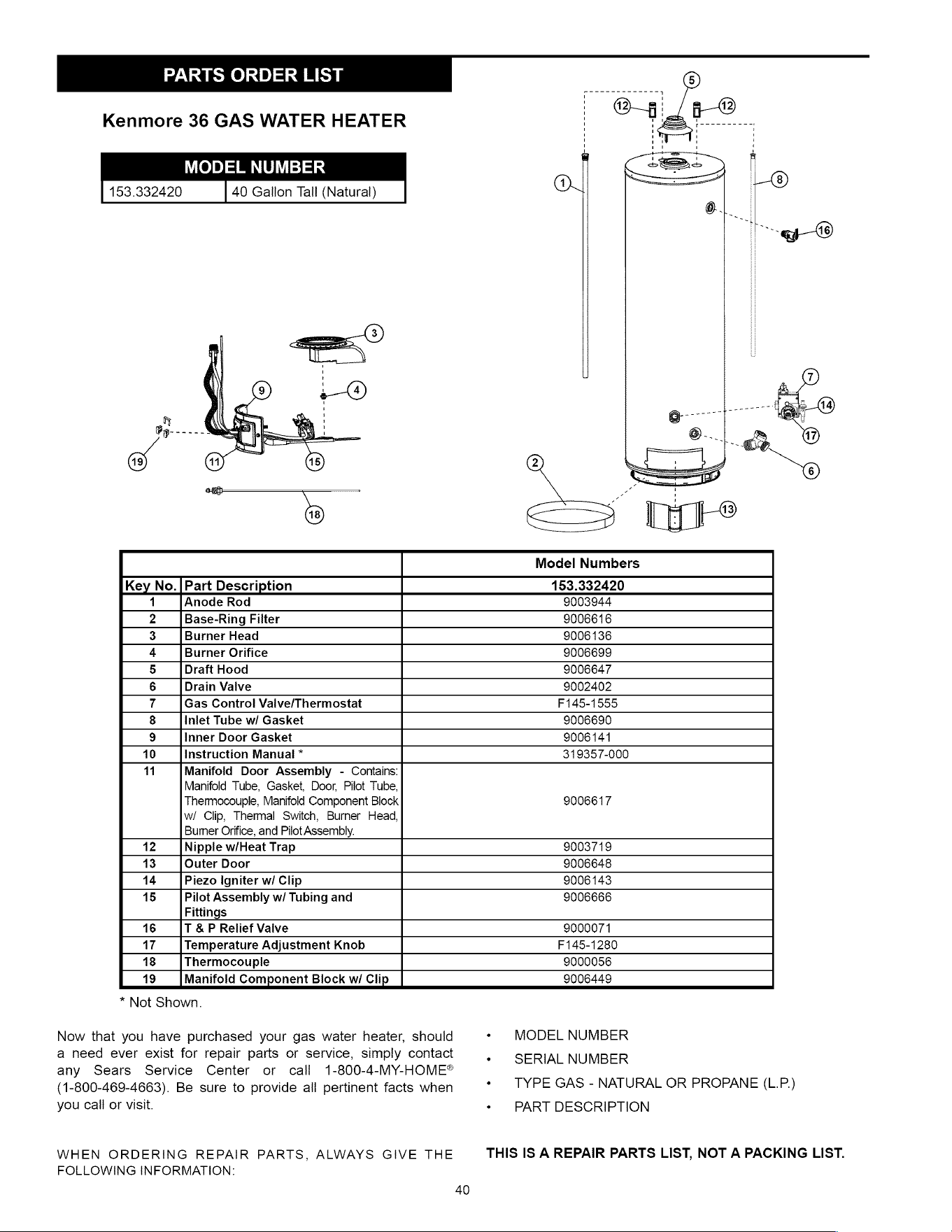
PARTS
ORDER
LIST
Kenmore
36
GAS
WATER
HEATER
ep
Sm
sta
153.332420
40
Gallon
Tail
(Natural)
Model
Numbers
Key
No.|Part
Description
153.332420
1
Anode
Rod
9003944
2
Base-Ring
Filter
9006616
3
Burner
Head
9006136
4
Burner
Orifice
9006699
5
Draft
Hood
9006647
6
Drain
Valve
9002402
7
Gas
Control
Valve/Thermostat
F145-1555
8
Inlet
Tube
w/
Gasket
9006690
9
Inner
Door
Gasket
9006141
10
Instruction
Manual
*
319357-000
11
Manifoid
Door
Assembly
-
Contains:
Manifold
Tube,
Gasket,
Door,
Pilot
Tube,
Thermocouple,
Manifold
Component
Block
9006617
wi
Clip,
Thermal
Switch,
Burner
Head,
Burner
Orifice,
and
Pilot
Assembly.
12
Nipple
w/Heat
Trap
9003719
13
Outer
Door
9006648
14
Piezo
Igniter
w/
Clip
9006143
15
Pilot
Assembly
w/
Tubing
and
9006666
Fittings
16
T
&
P
Relief
Vaive
9000071
17
Temperature
Adjustment
Knob
F145-1280
18
Thermocouple
9000056
19
Manifold
Component
Block
w/
Clip
9006449
*
Not
Shown.
Now
that
you
have
purchased
your
gas
water
heater,
should
a
need
ever
exist
for
repair
parts
or
service,
simply
contact
any
Sears
Service
Center
or
call
1-800-4-MY-HOME®
(1-800-469-4663).
Be
sure
to
provide
all
pertinent
facts
when
you
call
or
visit.
WHEN
ORDERING
REPAIR
PARTS,
ALWAYS
GIVE
THE
FOLLOWING
INFORMATION:
40
+
MODEL
NUMBER
+
SERIAL
NUMBER
«
TYPE
GAS
-
NATURAL
OR
PROPANE
(L.P.)
«+
PART
DESCRIPTION
THIS
IS
A
REPAIR
PARTS
LIST,
NOT
A
PACKING
LIST.

NOTES
a
Your
Home
For
troubleshooting,
product
manuals
and
expert
advice:
@
managemylife
www.managemylife.com
For
repair
—
in
your
home
—
of
all
major
brand
appliances,
lawn
and
garden
equipment,
or
heating
and
cooling
systems,
no
matter
who
made
it,
no
matter
who
sold
it!
For
the
replacement
parts,
accessories
and
owner’s
manuals
that
you
need
to
do-it-yourself.
For
Sears
professional
installation
of
home
appliances
and
items
like
garage
door
openers
and
water
heaters.
1-800-4-MY-HOME®
(1-800-469-4663)
Call
anytime,
day
or
night
(U.S.A.
and
Canada)
www.sears.com
Wwww.sears.ca
Our
Home
For
repair
of
carry-in
items
like
vacuums,
lawn
equipment,
and
electronics,
call
anytime
for
the
location
of
your
nearest
Sears
Parts
&
Repair
Service
Center
1-800-488-1222
(U.S.A)
1-800-469-4663
(Canada)
www.sears.com
www.sears.ca
To
purchase
a
protection
agreement
on
a
product
serviced
by
Sears:
1-800-827-6655
(U.S.A)
1-800-361-6665
(Canada)
Para
pedir
servicio
de
reparacion
Au
Canada
pour
service
en
frang¢ais:
a
domicilio,
y
para
ordenar
piezas:
1-800-LE-FOYER™:
1-888-SU-HOGAR®
(1-800-533-6937)
(1-888-784-6427)
www.sears.com
Sears
®
Registered
Trademark
/
™
Trademark
of
KCD
IP,
LLC
in
the
United
States,
or
Sears
Brands,
LLC
in
other
countries
®
Marca
Registrada
/
™
Marca
de
Fabrica
de
KCD
IP,
LLC
en
Estados
Unidos,
o
Sears
Brands,
LLC
in
otros
paises
MC
Marque
de
commerce
/
“°
Marque
déposée
de
Sears
Brands,
LLC