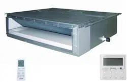

Models:
Indoor Unit
DUCT09HP230V1AD
DUCT12HP230V1AD
DUCT18HP230V1AD
DUCT24HP230V1AD
SLIM CONCEALED DUCT
INSTALLATION MANUAL

Thank you for choosing a
Gree Slim Concealed Duct
unit for your customer.
Please read this installation manual carefully before installing and starting up the
Slim Duct System. Take a moment to fill out the product and installation form on the
back cover. Retain both the manual and installation record for future reference.
Table of Contents
Safety Precautions . . . . . . . . . . . . . . . . . . . . . . . . . . . . . . . . . . . . . . . . . . . . 2
Nomenclature . . . . . . . . . . . . . . . . . . . . . . . . . . . . . . . . . . . . . . . . . . . . . . . . 3
System Requirements . . . . . . . . . . . . . . . . . . . . . . . . . . . . . . . . . . . . . . . . . . 3
Suggested Tools . . . . . . . . . . . . . . . . . . . . . . . . . . . . . . . . . . . . . . . . . . . . . . 4
System Schematic
. . . . . . . . . . . . . . . . . . . . . . . . . . . . . . . . . . . . . . . . . . . .
5
Installation Site Instructions . . . . . . . . . . . . . . . . . . . . . . . . . . . . . . . . . . . . . 6
Indoor Unit Installation . . . . . . . . . . . . . . . . . . . . . . . . . . . . . . . . . . . . . . . 7-9
Piping Installation . . . . . . . . . . . . . . . . . . . . . . . . . . . . . . . . . . . . . . . . . 10-13
Ductwork Installation . . . . . . . . . . . . . . . . . . . . . . . . . . . . . . . . . . . . . . 14-17
Power and Wiring Installation . . . . . . . . . . . . . . . . . . . . . . . . . . . . . . . 18-20
Controller Installation and Setup . . . . . . . . . . . . . . . . . . . . . . . . . . . . . . . . 21
Testing and Inspection . . . . . . . . . . . . . . . . . . . . . . . . . . . . . . . . . . . . . . . . 22
Troubleshooting . . . . . . . . . . . . . . . . . . . . . . . . . . . . . . . . . . . . . . . . . . 23-24
Diagnostic Codes . . . . . . . . . . . . . . . . . . . . . . . . . . . . . . . . . . . . . . . . . 25-28
Care and Cleaning . . . . . . . . . . . . . . . . . . . . . . . . . . . . . . . . . . . . . . . . . . . 29
SAFETY PRECAUTIONS
Please read the following before installation.
This is the safety alert symbol. It is used to alert you to potential
personal injury hazards. Obey all safety messages that follow this
symbol to avoid possible injury or death.
This mark indicates procedures which, if improperly performed,
might lead to the death or serious injury of the user.
This mark indicates procedures which, if improperly performed, might
possibly result in personal harm to the user, or damage to property.
Notice is used to address practices not related to personal injury.
General Safety Precautions
1. Instructions for installation and use of this product are provided by the manufacturer.
For proper operation, the system must be installed in accordance with this
installation manual.
2. Installation must be performed in accordance with local laws, regulations and
National Electrical Codes (NEC).
3. If refrigerant leaks while work is being carried out, ventilate the area. Do not allow
refrigerant to come in contact with a flame as it produces toxic gas.
4. Disconnect all electrical power to the indoor and outdoor units until the system is
ready for start-up and checkout.
5. When installing or repairing the system, use only R410A refrigerant. Do not
mix refrigerant with other gases. If air or other gas enter the refrigeration system,
the pressure inside the system may rise to an abnormally high value and cause
damage or injury.
This appliance is not intended for use by persons (including children) with reduced physical,
sensory or mental capabilities, or lack of experience and knowledge, unless they have been given
supervision or instruction concerning use of the appliance by a person responsible for their safety.
WARNING
CAUTION
NOTICE
WARNING
2
Indoor unit
NOMENCLATURE
SYSTEM REQUIREMENTS
PIPE SIZE in (mm)
Condensate Drainage: The unit has two gravity drain ports and a factory installed condensate pump with an
outlet port. Any condensate port not used must be plugged and insulated. The condensate pump operates when the unit
is running; if a gravity drain port is desired, the pump must be disconnected from the control board and the condensate
pump power plug must be electrically insulated to prevent an accidental short circuit. Use piping of the same diameter or
larger as the unit connection. Local code should be referenced for approved condensate piping for your area.
Interconnecting Cable
The ceiling duct unit is powered from the outdoor unit. Use recommended 14/4 AWG stranded
copper conductors THHN 600V unshielded wire.
Unit Size
(BtuH)
9,000 1/4 (6) 3/8 (9.5) 49/60 lbs.
12,000 1/4 (6) 3/8 (9.5) 51/64 lbs.
18,000 1/4 (6) 1/2 (12) 60/79 lbs.
24,000 3/8 (9.5) 5/8 (16) 68/90 lbs.
Net/Gross Weight
Liquid Line Suction/Gas Line
NOTE:
Insulate all condensate drain pipes to prevent sweating and possible water damage.
NOTE:
Use shield cable if installation is in close proximity of RF and EMI transmitting devices.
3
Cooling Capacity
09 - 9,000 BTUH
12 - 12,000 BTUH
18 - 18,000 BTUH
24 - 24,000 BTUH
Series Designation
Revision Level
Style/Color Designation
Product Type
S - System
O - Outdoor units
H - Indoor High Wall
D - Indoor Duct
C - Indoor Cassette
F - Indoor Floor/Ceiling
Electrical Rating
230V - 208/230V 60Hz 1PH
Model Type
HP - Heat Pump
115V - 115V 60Hz 1PH
Example: DUCT24HP230V1AD
DDUCT 24 HP 230V 1 A
MULTI - Multiple Port Outdoor Unit
DUCT - Slim Duct
CAS - Ceiling Cassette
FLR - Floor/Ceiling
CONS - Floor Console
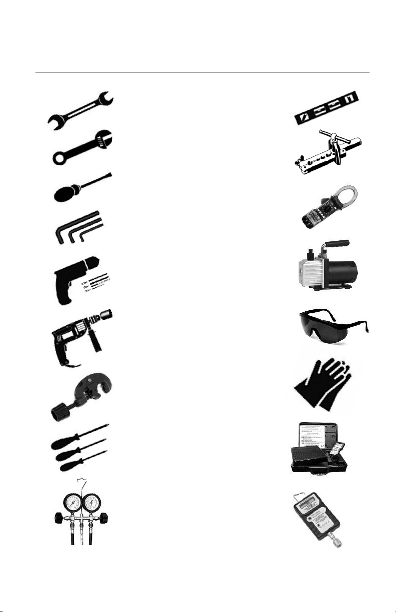
• Standard Wrench
• Adjustable/Crescent Wrench
• Torque Wrench
• Hex Keys or Allen Wrenches
• Drill & Drill Bits
• Hole Saw
• Pipe Cutter
• Screw drivers (Phillips & Flat blade)
• Manifold and Gauges
• Level
• R410A Flaring Tool
• Clamp on Amp Meter
• Vacuum Pump
• Safety Glasses
• Work Gloves
• Refrigerant Scale
• Micron Gauge
SUGGESTED TOOLS
4
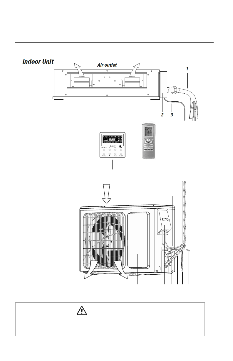
SYSTEM COMPONENTS
COMPONENT NAMES
*
Outdoor Unit
Air
outlet
Air inlet
11
10
98
12
7
The refrigerant pipe, drain pipe, electrical wiring, and duct for this unit should be installed
by a qualified HVAC professional only.
CAUTION
6
45
5
*
Not all items included with
equipment purchas
e
1. Gas & Liquid Pipes
2. Electric Box
3 Interconnection Cable
4. XK19 Wired Controller
5. Remote Controller
6. Interconnection Cable
7. Front Panel
8. Service Cover
9. Liquid Pipe
10. Gas Pipe
11. Drain Hose
12. Outdoor Power Supply
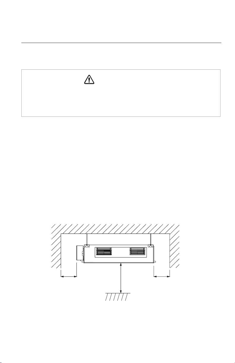
INSTALLATION SITE INSTRUCTIONS
Indoor Unit
The unit must be installed in a location which can withstand twice the weight of the unit.
Inadequate building support at the installation location may result in serious property
damage and injuries.
Review the installation location with the customer as follows:
1. Ceiling is strong enough to support twice the weight of the unit.
2. Ductwork can easily be installed using the shortest amount of duct.
3. Location allows easy installation of drain pipe.
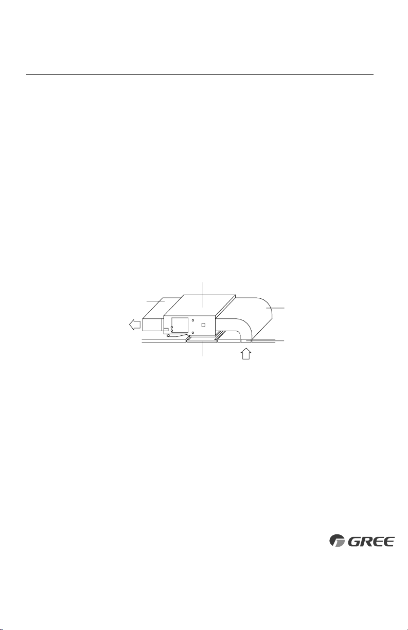
4. Space is left around the unit as required in Fig. 1.1 for future service and maintenance.
5. Air inlet and outlet registers of the unit should never be blocked, so airflow can reach
every corner of the room.
WARNING
Fig. 1.1
>10 in.
>72 in.
>10 in.
6
For the units: 9 -12K
For the units: 18K
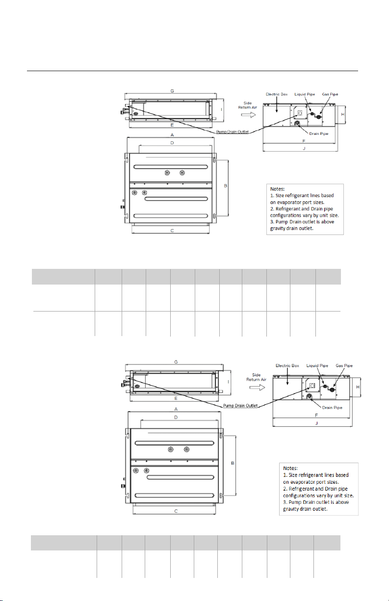
INDOOR UNIT INSTALLATION
Model ABCDEF GHI J
DUCT18HP230V1AD
37.1 19.3 33.9 32.3 35.4 24.2 38.7 6.1 7.9 25.0
(942) (491) (862) (820) (900) (615) (982) (156) (200) (635)
INDOOR UNIT DIMENSIONS in (mm)
Model ABCD EFGHI J
DUCT09HP230V1AD
29.2 19.3 26.1 24.4 27.6 24.2 30.8 6.1 7.9 25.0
(742) (491) (662) (620) (700) (615) (782) (156) (200) (635)
29.2 19.3 26.1 24.4 27.6 24.2 30.8 6.1 7.9 25.0
DUCT12HP230V1AD
(742) (491) (662) (620) (700) (615) (782) (156) (200) (635)
INDOOR UNIT DIMENSIONS in (mm)
7
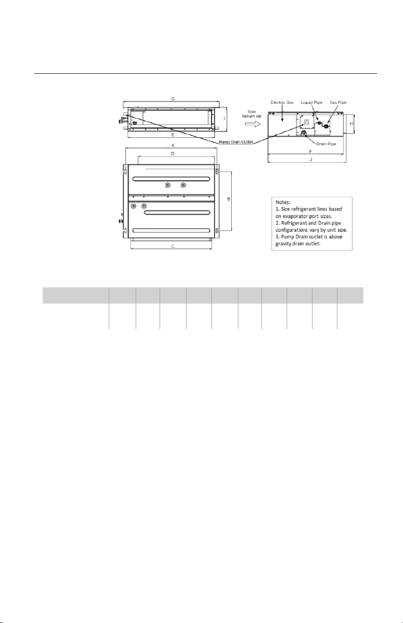
INDOOR UNIT INSTALLATION
For the units: 24K
Model AB C D EF GH I J
DUCT24HP230V1AD
44.3 19.3 41.8 40.2 43.3 24.2 46.5 6.1 7.9 25.0
(1124) (491) (1062) (1020) (1100) (615) (1182) (156) (200) (635)
INDOOR UNIT DIMENSIONS in (mm)
8
INDOOR UNIT INSTALLATION
Mounting Indoor Unit
It is critical to properly secure the indoor unit to a stable and rigid structure that can support twice
its weight for safety and product reliability.
Select the proper size suspension bolts or anchoring devices (field supplied) to support twice the
weight of the unit.
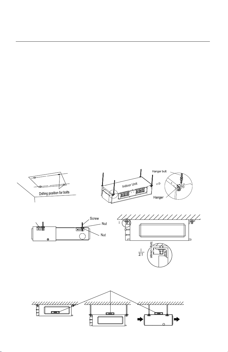
1. Locate a structure strong enough to support twice the weight of the unit.
2. Using the installation template supplied with the unit, mark the hole locations as shown in fig 2.1.
3. Drill 4 mounting holes for suspension bolts per the manufacturer's instructions.
4. Install 4 suspension bolts into pre-drilled holes.
5. Install the 4 hanger brackets to unit as shown in fig 2.2.
6 Add an upper nut to each suspension bolt.
7. Carefully lift unit and position the 4 hanger brackets on the suspension bolts.
8. Install a lower washer and nut to each suspension bolt to secure unit as shown in fig 2.3.
9. Adjust the unit height to desired position.
Leveling
After the indoor unit is installed and adjusted to proper height, check the unit position to ensure that the
unit is level as shown below.
Fig. 2.1 Fig. 2.2
Fig. 2.4
Fig. 2.3
Level Bar
Hanger
9
Piping Preparation
1. Do not open service valves or remove protective caps on pipes until instructed by this manual.
2. Keep tubing free of dirt, sand, moisture and contaminants.
3. Insulate each refrigerant pipe and condensate hose with minimum 3/8” (10 mm) wall
thermal pipe insulation.
4. Bind refrigerant pipes and interconnecting cable together with cable ties at 12-inch intervals.
5. Include the condensate hose in bundle for exterior portion only.
PIPING INSTALLATION
Refrigerant Piping
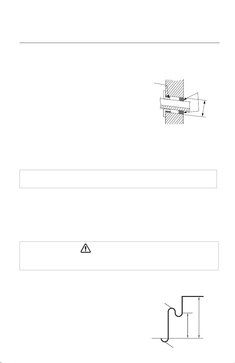
Drill Hole in Wall
1.
Locate and mark proper location for the wall hole.
2.
Cut the 2 3/4” wall hole with a 5° to 10°
downward slant to the outdoors.
3. Insert a wall sleeve (field supplied) into hole to
to prevent damage to refrigerant pipes, insulation,
condensate drain hose and wiring.
4. Proper weather proofing of the wall surface and
wall sleeve is essential to assure a trouble-free
installation. Apply sealant, caulking or equivalent weather proofing material around
the perimeter of the wall sleeve (interior & exterior) to eliminate outdoor air and water
leaks into the living space.
NOTE: Expandable foam insulation may be added to fill large wall gaps. Apply per
manufacturer's instructions.
Seal Hole
Hole Size
Indoor
Outdoor
Wall Hole Diagram
Oil return bend
Indoor
Outdoor
20 ft.
30 ft.
Oil return bend
Indoor Unit below Outdoor Unit Application
When height difference between indoor unit and outdoor
unit is more than 30 feet, an oil return bend should be added
for every 20 feet of connection pipe as shown.
Wall
Hole Sleeve
Insulate entire interior section of condensate hose to prevent sweating which may cause water
stains or wall damage.
CAUTION
10
PIPING INSTALLATION
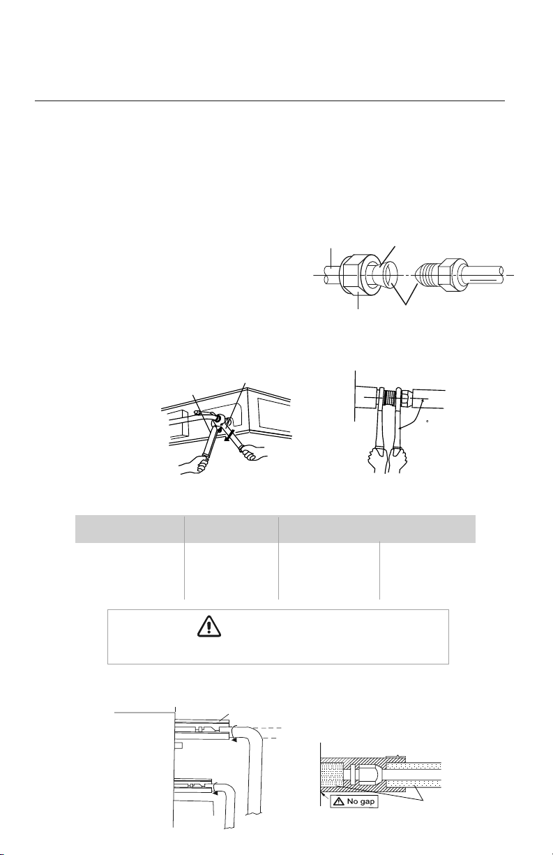
Indoor Unit Pipe Connections
1. Feed refrigerant pipes, drain hose and interconnecting wires assembly through wall hole
from outdoor to the indoor unit.
2.
Pull the piping assembly to the indoor unit. Carefully bend refrigerant pipes to meet indoor unit
connection ports. Use proper tools to avoid kinks.
3. Add a small amount of refrigerant oil to
both ends of the flare fittings.
4. Starting with either refrigerant pipe, carefully
center the pipe to the indoor unit connection
port then hand tighten the flare nut.
5. Repeat procedure with remaining pipe.
6. Tighten both flare nuts using a standard wrench and a torque wrench as shown below.
7. Carefully tighten flare nuts to correct torque level referring to the Torque Table below.
8. Individually insulate each bare refrigerant pipe and joint as shown below to prevent sweating.
Pipe Diameter Nut Size
Tightening Torque
inch (mm) inch (mm) ft-lbs N-m
1/4 (6.35) 1/4 (17) 11 to 22 15 to 30
3/8 (9.5) 3/8 (22) 26 to 30 35 to 40
1/2 (12.0) 1/2 (25) 33 to 37 45 to 50
5/8 (15.9) 5/8 (29) 44 to 48 60 to 65
Liquid pipe
Gas pipe
Front outlet
Insulate pipe connection
Insulate pipe
Reference A:
R
Cover this portion with insulation
Pipe insulation
L
Over tightening may damage flare connections and cause leaks.
CAUTION
Copper
piping
Oil applied
(to reduce friction
with the flare nut)
Flare nut
Oil applied
(improves seal
air-tightness)
90
90
Holding spanner
Torque wrench
11
System with
P-Trap and VentTypical Drainage System
Indoor Condensate Drain Piping
PIPING INSTALLATION
Observe all local sanitary codes when installing condensate drains.
WARNING
It is recommended to install the condensate drain system with hard polyvinyl chloride (PVC) pipe
and matching connectors. Use piping of the same diameter or larger as the unit connection.
The unit has two drain ports, one on the left side or electric box side (Factory Default) and one on
the right side of the unit. To use the right side drain port, remove the drain plug from the port and
re-install it on the left or electric box side drain port.
Pitch the condensate drain pipe at a gradual 2.5% pitch (Example: ¼-in drop over a 10-in length) without
obstructions. Use pipe hanger/brackets to support the condensate drain pipe from sagging or drooping.
NOTE: Insulate condensate hose and/or pipes to prevent sweating which may cause
water stains or wall damage.
Outdoor Unit Pipe Connections
Carefully bend and adjust length of refrigerant pipes to meet
outdoor unit port connections. See installation instructions
shipped with the outdoor unit for further instructions..
See Table below for Condensate Drainage port size.
Capacity Size (BtuH) Drain Connection Size
(OD)
9,000 - 24,000 1.0 (26)
12
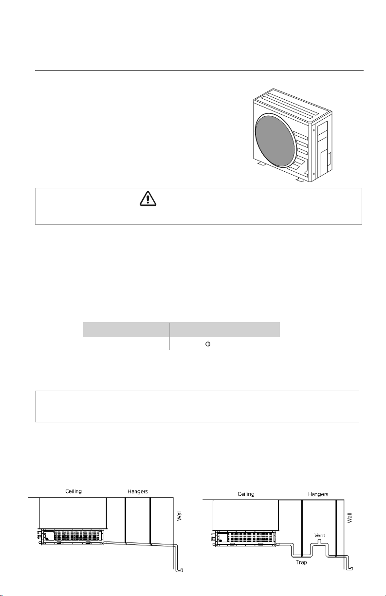
The following are recommended gravity drainage systems for the ceiling duct.
Gravity Drainage Systems
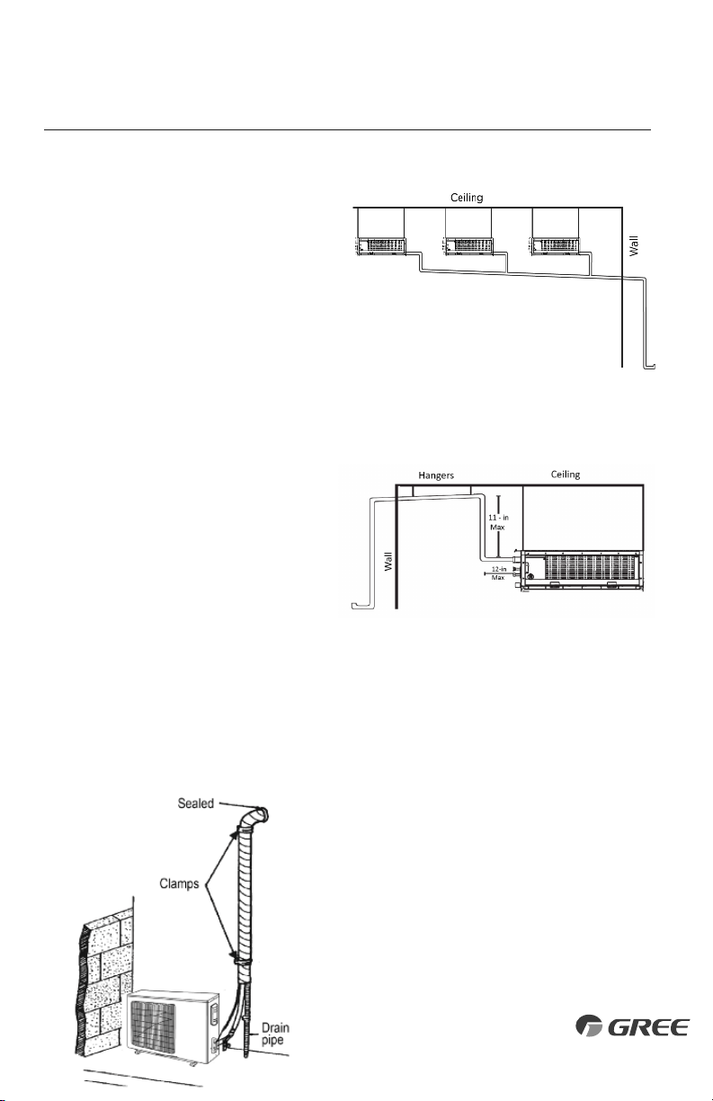
PIPING INSTALLATION
Completing Condensate Drainage Piping
•
Include the condensate hose in the pipe/wire bundle
for the exterior/outdoor section.
•
Fasten the refrigerant and condensate pipe assembly
to the exterior wall for support.
•
The drain pipe should terminate 6 inches above grade.
If a gradual 2.5% pitch is not obtainable, the indoor unit has a condensate drain pump with limited
head or lift. An 11-in (max) riser pipe may be added within the first 12 inches to create a proper
pitch for the drainage system.
Multiple Units with Common Drain
The following is the recommended condensate
drainage system for multiple units that share a
common drain line. Connecting multiple units
to one trap allows air to be pulled through one
or more of the units, bypassing the trap. An
alternate method is having individual drains
and traps for each unit.
Vertical Lift Drainage System
Use an auxiliary condensate pump (field
supplied) with float valve for vertical height
greater than 11-in. above the unit drainage
port. A float valve is recommended to shut
off the system if the auxiliary pump fails.
13
(Internal Condensate Pump)
(Gravity Drain Configuration)
The unit has two gravity drain ports and a factory installed condensate pump with an outlet port. The
condensate pump port must be utilized for condensate removal or the pump may be
disconnected from the control board if a gravity drain port is desired. If disconnected the
condensate pump plug must be electrically insulated to prevent an accidental short circuit. Use piping of
the same diameter or larger as the unit connection. Local code should be referenced for approved
condensate piping for your area.
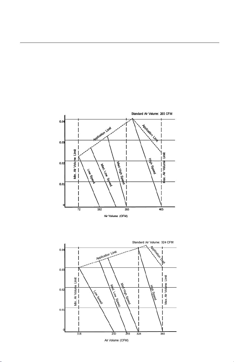
The ductwork configuration should be based on the conditions of the building and maintenance
etc., as shown below.
DUCTWORK INSTALLATION
Design and Layout of Ductwork
Indoor Fan Performance and Air Volume
DUCT09HO230V1AD
DUCT12HO230V1AD
14
External Static Pressure (InWg)External Static Pressure (InWg)
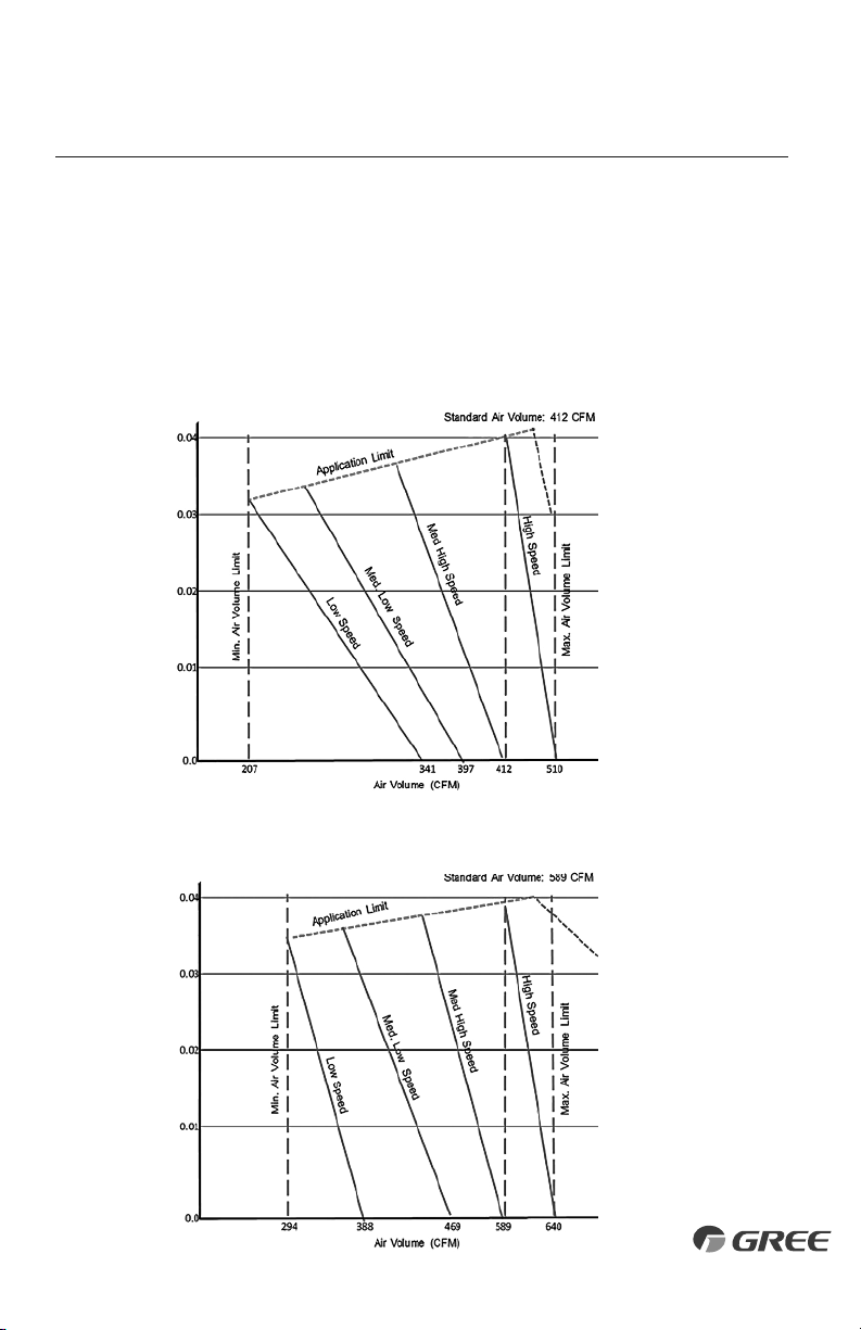
The ductwork configuration should be based on the conditions of the building and maintenance
etc., as shown below.
DUCTWORK INSTALLATION
Design and Layout of Ductwork
Indoor Fan Performance and Air Volume
DUCT18HO230V1AD
DUCT24HO230V1AD
15
External Static Pressure (InWg)External Static Pressure (InWg)
DUCTWORK INSTALLATION
Duct Sizing Suggestions
Correct ductwork design is critical to insure proper system performance. The total length of the ductwork
is the length from the return air duct register to the supply air register. It is recommended that the ductwork
and register selection should follow ACCA manual D duct design to insure proper velocity and air flow.
Capacity Size (BtuH) 9K 12K 18K 24K
Air Flow Rate (CFM) 265 324 412 589
Ext. Static Pressure (InWg) 0.04 0.04 0.04 0.04
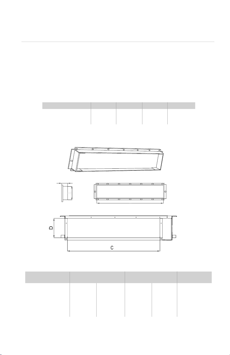
Model
Supply Duct (in/mm) Return Duct (in/mm)
Flange(in/mm)
ABCD E
DUCT09HP230V1AD 6.1/156 26.1/662 22.8/580 6.4/162 0.8/21
DUCT12HP230V1AD 6.1/156 26.1/662 22.8/580 6.4/162 0.8/21
DUCT18HP230V1AD 6.1/156 33.9/862 30.7/780 6.4/162 0.8/21
DUCT24HP230V1AD 6.1/156 41.8/1062 38.6/980 6.4/162 0.8/21
SUPPLY AIR OUTLET/RETURN AIR INLET DIMENSIONS in (mm)
MAX. EXT. STATIC PRESSURE
B
21mm(7/8inch)
A
Duct Connection Requirements
Side View
Supply Air Outlet
Return Air Inlet
16
1
3
4
6
5
Supply air
Return air
Part Name
1. Return Air Inlet (with filter)
2. Canvas Duct
3. Return Air Duct
4. Indoor Unit
5. Supply Air Duct
6. Access Cover ( 18K Only)
DUCTWORK INSTALLATION
1. Connect return air duct (#3) to the return air inlet of the unit (#4) and the other end to a return
air register. Ensure return ductwork is properly supported with hangers.
2. Connect supply air duct (#5) to the supply air outlet of the unit (#4) and the other end to a
discharge air register. Ensure supply ductwork is properly supported with hangers.
Attaching Ductwork to Indoor Unit
17
POWER AND WIRING INSTALLATION
WARNING
1. Before obtaining access to electrical box and terminals, all electrical supply circuits must
be disconnected.
2. Use a circuit breaker with adequate capacity to meet the requirements of the total system.
3. A circuit breaker or fuse should be installed per the National Electric Code (NEC) and
local regulations.
4. Electrical wiring must be completed in accordance with NEC, local laws, and regulations
of the electric company so that the system will operate properly.
5. Provide a GFI circuit breaker at the electrical panel in accordance with the NEC and the
local electrical company standards.
6. Connect the connection wires firmly to the terminal block. Improper installation may
cause a fire.
CAUTION
1. If the indoor unit communication wire (to the outdoor unit) and power wire are connected
incorrectly, the air conditioner may be damaged.
2.
Ground both indoor unit and outdoor unit to earth ground in accordance with the applicable
local and national codes.
18
POWER AND WIRING INSTALLATION
Outdoor Unit Electrical Wiring
For Outdoor Unit wire connections, see installation instructions shipped with the outdoor unit.
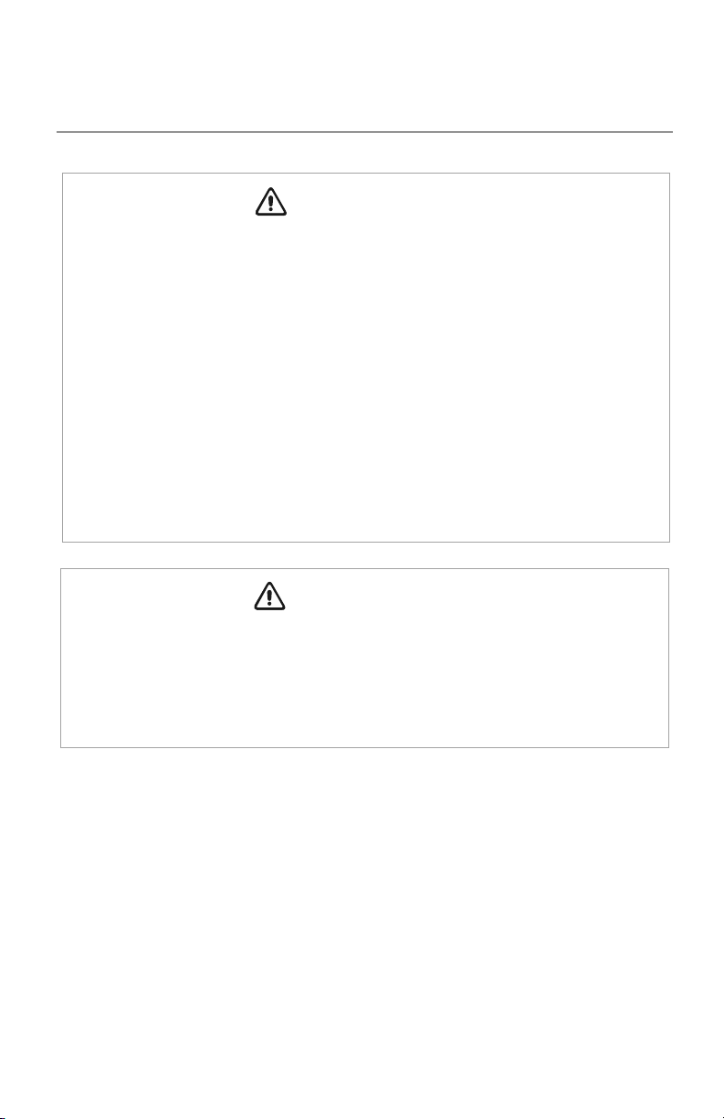
Electric Wiring Between Indoor Unit and Outdoor Unit
G
Power:
Wired Tether
Controller
XK-19
NN
(
N
(
1N
(
1
)
N
(
1
)
22
33
CN1CN1
22
33
NN
(
N
(
1N
(
1
)
N
(
1
)
CN9
N
(
1
)
CN9
Duct Unit
Typical Wiring Diagram
Red
White
Black
Green
Indoor Unit Electrical Wiring
Locate and remove the electrical box cover to access wire terminals.
19
POWER AND WIRING INSTALLATION
Electrical Connections to Concealed Duct
Disconnect all electrical power to indoor and outdoor units including disconnects,
fuses and circuit breakers. Lockout and tag all disconnect switches.
1. Adjust the length of the interconnecting wires so that it can easily reach the indoor unit
electrical control box.
2. Open electrical control box cover and route the interconnecting wires to field wiring terminal block.
NOTE:
The indoor unit is powered from the outdoor unit, depending on local code, a
disconnect switch may need to be installed to a power supply circuit.
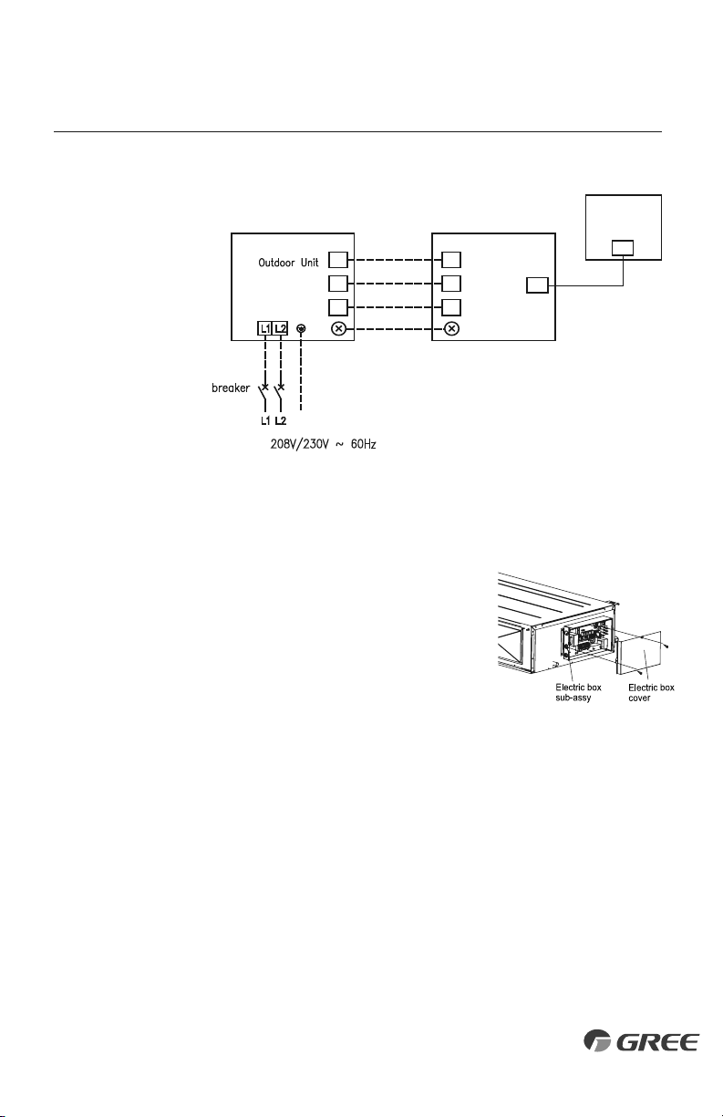
3. Secure interconnecting wires to the terminal block
as shown in the connection diagram at right:
NOTE:
Record wire colors and terminal references
for uses with Outdoor Unit wire connections.
4. Secure all wires inside wire clamp/strain relief. Verify wires
are secure, not loose and no external force on wires affects
the connections at the terminals.
NOTE:
Crossing interconnecting wires will cause system malfunction and possible damage.
5. Replace electrical box cover on unit.
WARNING
Red
White
Black
Green
Outdoor Unit
Indoor Unit
Indoor Unit
Disconnect Switch
Wires
Outdoor Unit
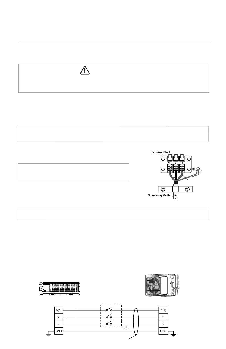
Local codes may require a disconnect switch within sight of the indoor unit. Use a DFS Disconnect
Switch Accessory Kit (Part No: DFS-SWITCH-A) to break interconnecting wires going to the N(1),
2, 3, terminals on the indoor unit, as shown in the wiring diagram below:
Indoor Disconnect Switch (Optional)
Red
White
Black
Green
20
CONTROLLER INSTALLATION AND SETUP (Optional)
The following is a brief overview of the Wired Tether Controller installation. See Tether Controller
Owner's Manual for more detailed instructions for setup and operation.
Preparation for Installation
Select a proper location on the wall for mounting the
Tether Controller. Install switch box, if required by code.
The maximum wire length between indoor unit and Tether
Controller is 26 ft (8m). Route electrical cable (provided)
between indoor unit and selected wall mounting location.
See Indoor Unit wiring section for diagram to connect
the Wired Tether Controller to the indoor unit.
Route communication cable to main control board in
electrical box. Location connector CN9 on main control
board. Carefully connect cable to main control board
connector.
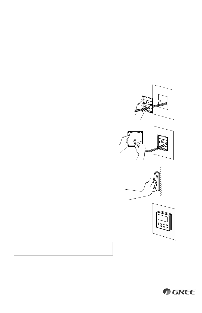
Wired Tether Controller Installation
Pull communication cable through switch box (if one
is used) and Wired Tether Controller backplate. Securely
fasten backplate to the switch box or wall.
Locate wire terminals connector on rear of Tether
Controller panel. Carefully connect cable to controller
connector. Verify connector is secure, not loose and
no external force on wires affects the connections at
the terminals. Push extra cable into wall and secure
controller panel to backplate mounted on the wall.
NOTE: Do not cut or splice communication cable.
21
TESTING AND INSPECTION
Start-up Checklist
□
Turn on main power to indoor and outdoor units.
•
Verify the system is not displaying an error code on the indoor unit or Tether Controller display.
□
Press the ON button on the Tether Controller.
• Verify the Tether Controller display turns ON.
□
Press the Mode button to Cooling.
Adjust the room setpoint to bring the system on in cooling mode. The system should start
cooling mode within 3-5 minutes.
• Verify the outdoor fan and compressor are operating.
• Verify the indoor fan is operating.
• Verify the indoor discharge air is cooling the room.
□
Press the Mode button to Heating.
Adjust the room setpoint to bring the system on in heating mode. The system should start
heating mode within 3-5 minutes.
• Verify the outdoor fan and compressor are operating.
• Verify the indoor fan is operating.
• Verify the indoor discharge air is heating the room.
□
Press the OFF button on the Tether Controller.
• Verify Tether Controller display turns OFF and the system shuts OFF.
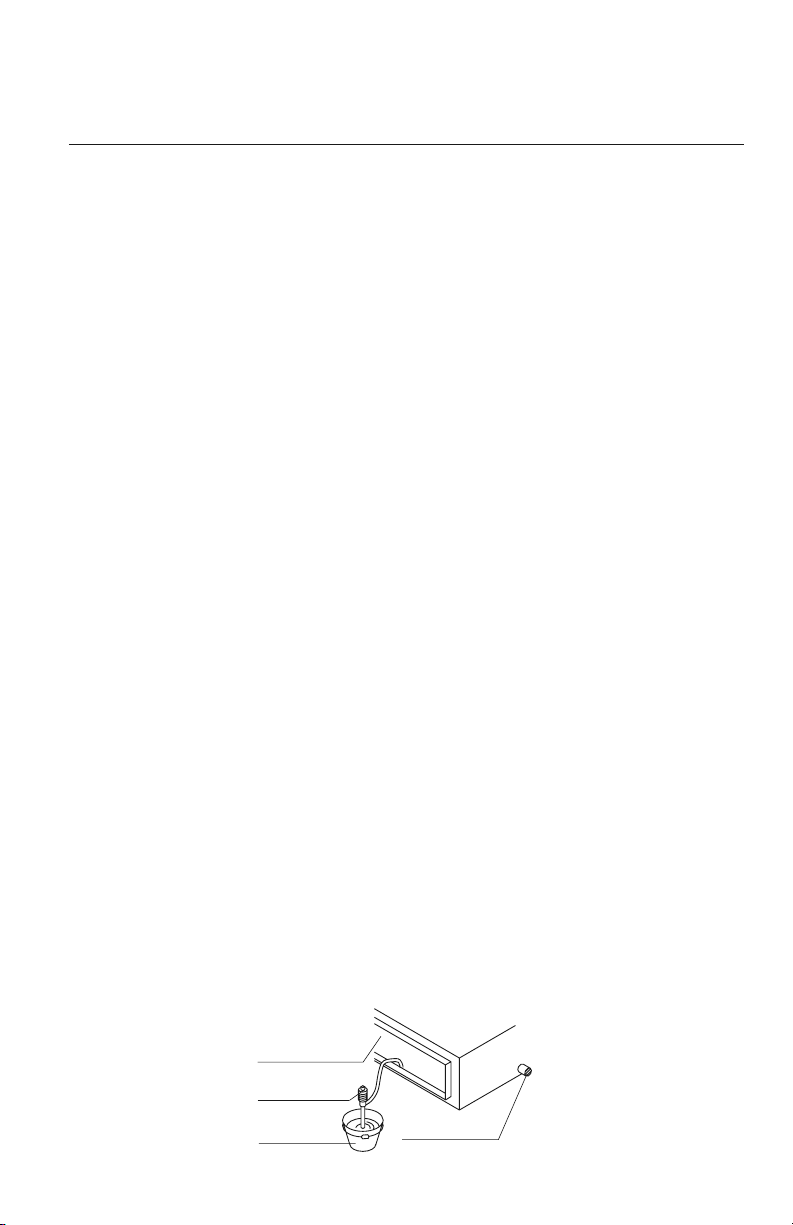
□
Test the Drain Piping.
• Verify condensate water drains smoothly. As shown in the figure, add approximately
1 quart of water slowly into the drain pan. The condensate pump should turn on and drain
the water through the condensate drain pipe to a safe location. Verify there are no leaks
in the condensate pipe and connections.
Air outlet
Portable pump
Bucket
Drain outlet
22
TROUBLESHOOTING
PROBLEM
System does not restart.
Indoor unit emits unpleasant odor
when started
You hear a“water flowing”sound.
A thin fog or vapor coming out
of the discharge register when
system is running.
You hear a slight cracking sound
when the system stops or starts.
The system will not run.
The unit is not heating or cooling
adequately.
CAUSE/SOLUTION
Cause: The system has a built-in three-minute delay to prevent short and/or rapid
cycling of the compressor.
Solution: Wait three minutes for the protection delay to expire.
Cause: Typically unpleasant odors are the result of mold or mildew forming on
the coil surfaces or the air filter.
Solution: Wash indoor air filter in warm water with mild cleaner. If odors persist,
contact a qualified service professional to clean the coil surfaces.
Cause: It is normal for the system to make“water flowing”or“gurgling”sounds
from refrigerant pressures equalizing when the compressor starts and stops
Solution: The noises should discontinue as the refrigerant system equalizes after
two or three minutes.
Cause: It is normal for the system to emit a slight fog or water vapor when
cooling extremely humid warm air.
Solution: The fog or water vapor will disappear as the system cools and
dehumidifies the room space.
Cause: It is normal for the system to make “slight cracking” sounds from parts
expanding and contracting during system starts and stops.
Solution: The noises will discontinue as temperature equalizes after 2 or 3 minutes.
Cause: There are a number of situations that will prevent the system from running.
Solution: Check for the following:
• Circuit breaker is “tripped” or “turned off.”
• Power button of Tether Controller is not turned on.
• Tether Controller is in sleep mode or timer mode.
• Otherwise, contact a qualified service professional for assistance.
Cause: There are a number of reasons for inadequate cooling or heating.
Solution: Check the following:
• Remove obstructions blocking airflow into the room.
• Clean dirty or blocked air filter that is restricting airflow into the system.
• Seal around door or windows to prevent air infiltration into the room.
• Relocate or remove heat sources from the room.
23

TROUBLESHOOTING
PROBLEM
Water leakage from the
outdoor unit.
Water leaking from the indoor
unit into the room.
The unit will not deliver air.
CAUSE/SOLUTION
Cause: It is normal for the outdoor unit to generate condensate water in the
reverse cycle heating and defrost mode.
Solution: This is normal. No action is required.
Cause:
While it is normal for the system to generate condensate water in cooling
mode, it is designed to drain this water via a condensate drain system to a safe location.
Solution: If water is leaking into the room, it may indicate one of the following.
• The indoor unit is not level right to left. Level indoor unit.
• The condensate drain pipe is restricted or plugged. All restrictions must
be removed to allow continuous drainage by gravity.
• If problem persists, contact a qualified service professional for assistance.
Cause: There are a number of system functions that will prevent air flow.
Solution: Check for the following:
• In heating mode, the indoor fan may not start for three minutes if the
room temperature is very low. This is to prevent blowing cold air.
• In heat mode, if the outdoor temperature is low and humidity is high,
the system may need to defrost for up to 10 minutes before beginning
a heating cycle.
• In dry mode, the indoor fan may stop for up to three minutes during the
compressor off delay.
• Otherwise, you should contact a qualified service professional for assistance.
24
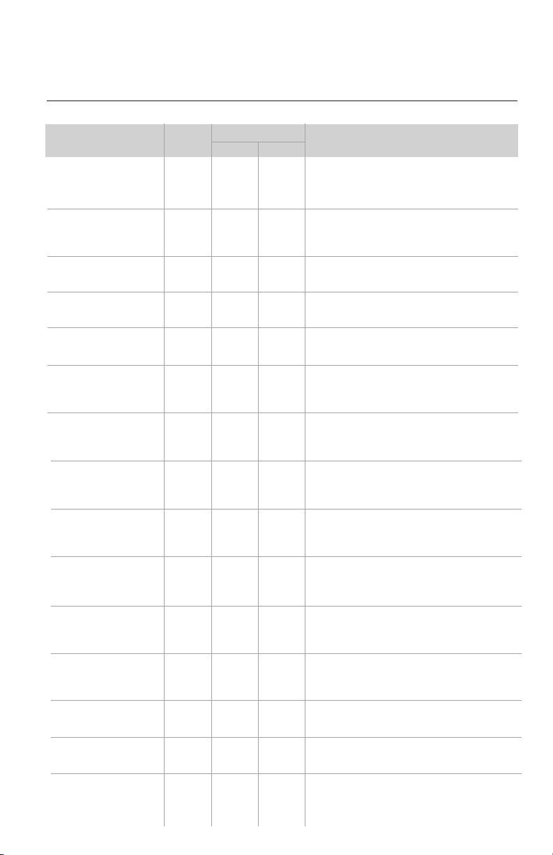
DIAGNOSTIC CODES
X-fan Mode
Indoor Evap Coil Temperature
Sensor Malfunction
Gas valve temperature sensor
is open/short circuited
System Configuration
Malfunction
Communication wire error or
electronic expansion valve
malfunction
Wrong connection of communication
wire or malfunction of electronic
expansion valve
System High Pressure
Indoor Anti-Freeze Protection
Low Pressure Protection
Compressor High Discharge
Temperature Protection
Overcurrent Protection
Communication Malfunction
Mode conflict (Indoor units
calling for simultaneously
Heating and Cooling)
Operation status
1) Loose or bad connection between sensor and control board
2) Indoor Evap Coil temperature sensor damaged
3) Control board malfunction
Hardware malfunction
1) No jumper cap inserted on the control board
2) Incorrect or damaged jumper cap on control board
3) Indoor and outdoor units are not compatible
Operation status
Hardware malfunction
1) Over charged with refrigerant
2) Blocked or dirty outdoor coil
3) Extreme outdoor ambient conditions
1) Low return airflow
2) Indoor fan speed is too low
3) Indoor coil is blocked or dirty
1) Low on refrigerant
2) Pressure sensor is damaged
Please refer to the malfunction analysis (discharge
temperature, overload) in service manual
1) Supply voltage is unstable
2) Supply voltage is too low and system load is too high
3) Indoor coil is blocked or dirty
1) Communication cable is mis-wired between indoor
and outdoor units
2) Indoor or Outdoor control board malfunction
Operation status
AL
b5
b7
C5
dd
dn
E1
E2
E3
E4
E5
E6
E7
Yellow
3 flashes
and 1 sec Off
7 flashes
and 1 sec Off
5 flashes
and 1 sec Off
Continuous
On
Red
9 flashes
and 1 sec Off
Troubleshooting
The unit has onboard diagnostics. The outdoor unit will provide status indicators. The indoor
wall unit and remote controller will display error codes. The following is a summary of the
codes with explanation:
Indoor Unit
& Remote
Display
Outdoor Unit Indicators
Malfunction Name Possible Causes
25
Indoor Unit
Display
Outdoor Unit Indicators
Malfunction Name Possible Causes
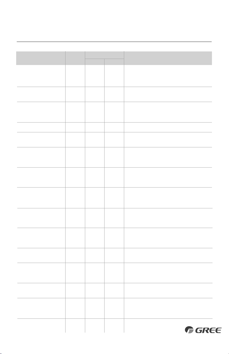
DIAGNOSTIC CODES
High Temperature
Resistant Protection
Cold Air Protection
EEPROM Memory Malfunction
Module Phase Current Protection -
Frequency Decrease/Limit Mode
Module Temperature Protection -
Frequency Decrease/Limit Mode
Refrigerant Leakage Protection
Indoor Ambient Temperature
Sensor Malfunction
Indoor Coil Temperature
Sensor Malfunction
Outdoor Ambient Temperature
Sensor Malfunction
Outdoor Coil Temperature
Sensor Malfunction
Outdoor Discharge Temperature
Sensor Malfunction
Compressor Overload Protection -
Frequency Decrease/Limit Mode
Oil Return Protection - Frequency
Decrease/Limit Mode
System Current Overload Protection -
Frequency Decrease/Limit Mode
High Compressor Discharge
Temperature - Frequency
Decrease/Limit Mode
1) Incorrect refrigerant charge level
2) Refrigerant metering device malfunction
3) Compressor malfunction
1) Indoor coil has not reach minimum heating temperature
2) Indoor ambient is abnormally cold
3) Indoor control board malfunction
Control board malfunction
Outdoor control board malfunction
1) IPM module over heating or malfunctioning
2) Improper voltage at IPM Module
1) refrigerant leak(s)
2) Indoor coil temperature sensor no calibrated
3) Refrigerant flow is restricted ( ex. valve, exv, debris)
1) Loose or bad connection between sensor and control board
2) Indoor ambient temperature sensor damaged
3) Control board malfunction
1) Loose or bad connection between sensor and control board
2) Indoor coil temperature sensor damaged
3) Control board malfunction
1) Loose or bad connection between sensor and control board
2) Outdoor ambient temperature sensor damaged
3) Control board malfunction
1) Loose or bad connection between sensor and control board
2) Outdoor coil temperature sensor damaged
3) Control board malfunction
1) Loose or bad connection between sensor and control board
2) Discharge temperature sensor damaged
3) Control board malfunction
1) Incorrect refrigerant charge
2) Metering device malfunction
3) Compressor malfunction
Normal function status code only
1) Input voltage too low
2) System pressure too low
1) Cooling load is too great
2) Outdoor ambient temperature too high
3) Refrigerant charge too low
4) Metering device malfunction
E8
E9
EE
En
EU
F0
F1
F2
F3
F4
F5
F6
F7
F8
F9
Yellow
6 flashes
and 1 sec Off
11 flashes
and 1 sec Off
Red
11 flashes
and 1 sec Off
9 flashes
and 1 sec Off
6 flashes
and 1 sec Off
5 flashes
and 1 sec Off
7 flashes
and 1 sec Off
3 flashes
and 1 sec Off
1 flashes
and 1 sec Off
2 flashes and
1 sec Off
26
Indoor Unit
Display
Outdoor Unit Indicators
Malfunction Name Possible Causes
DIAGNOSTIC CODES
Indoor Coil Freeze Protection -
Frequency Decrease/Limit Mode
Pump Down or Gathering
Refrigerant Status
High Indoor Coil Temperature
in Heating- Frequency
Decrease/Limit Mode
Defrost Mode in Heating
Compressor Overload Protection
Compressor Overload Protection
IPM Module Protection
Indoor DC Fan Motor
Malfunction
Compressor De-Synchronized
Malfunction
Power Factor Correction (PFC)
Protection
Compressor Demagnetization
Protection
Outdoor Fan Motor
Malfunction
High Input Power Protection
Start-Up Malfunction
Compressor phase-lacking/
phase-inverse protection
1) Indoor coil has not reach minimum heating temperature
2) Indoor ambient is abnormally cold
3) Indoor control board malfunction
Optional Service Mode
1) Incorrect refrigerant charge
2) Metering device malfunction
3) Compressor malfunction
Operation status
1) Wiring terminal OVC-COMP is loose
2) Refer to the malfunction analysis in Service Manual
1) Incorrect refrigerant charge
2) Metering device malfunction
3) Compressor malfunction
1) IPM module over heating
2) Improper or Low voltage at the IPM module
3) IPM module malfunction
1) Loose connections between fan motor and control board
2) Fan motor or blower wheel bearings malfunction
3) Control board malfunction
1) Compressor voltage is not balance
2) Control board malfunction
3) Compressor malfunction
1) Mis-wiring of the reactor filter and PFC capacitor
2) Reactor filter or PFC capacitor malfunction
3) Control board malfunction
Compressor malfunction
1) Loose connections between fan motor and control board
2) Fan motor malfunction
3) Control board malfunction
1) Compressor malfunction
2) Power circuit malfunction
1) Over charged with refrigerant
2) Control board malfunction
3) Compressor malefaction
Hardware malfunction
FH
Fo
H0
H1
H3
H4
H5
H6
H7
HC
HE
L3
L9
LC
Ld
Yellow
17 flashes
and 1 sec Off
8 flashes
and 1 sec Off
6 flashes and
1 sec Off
4 flashes
and 1 sec Off
14 flashes
and 1 sec Off
9 flashes
and 1 sec Off
Red
4 flashes
and 1 sec Off
14 flashes
and 1 sec Off
27
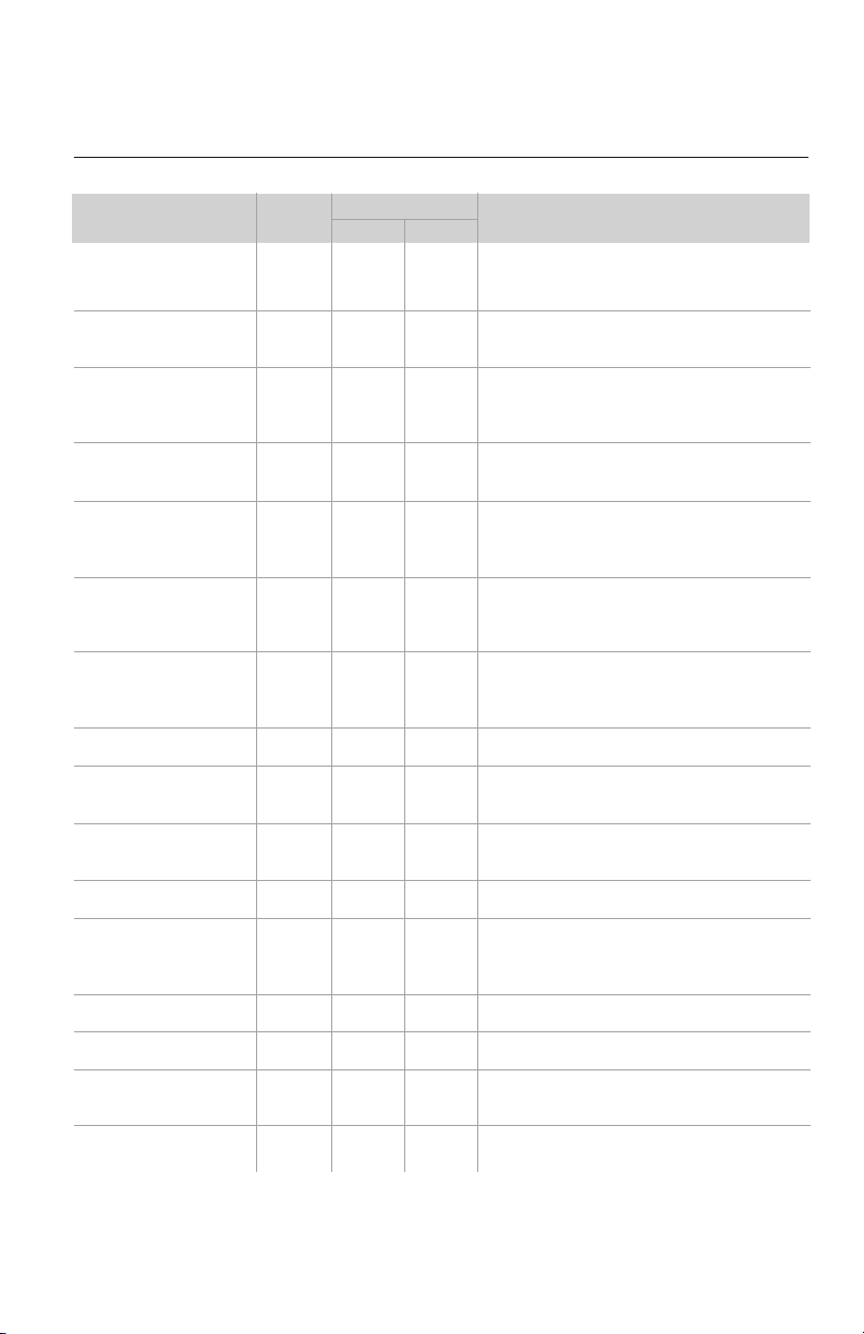
Notes: 1) During defrosting process, the heating indicator is on for 10s and off for 0.5s.
2) Refer to Service Manual for additional information.
Indoor Unit
Display
Outdoor Unit Indicators
Malfunction Name Possible Causes
DIAGNOSTIC CODES
Incompatible Indoor and
Outdoor Units
Defrosting Status
Compressor Phase Current
Protection
Module Temperature Sensor
Malfunction
Module Temperature Protection
High DC Bus Voltage Protection
Low DC Bus Voltage Protection
Capacitor Charging Malfunction
Compressor Phase-Current
Detection Malfunction
DC Bus Voltage Level Dropping
Malfunction
Current Detection Malfunction
Reversing Valve Malfunction
Input Current Detection Malfunction
The four-way valve is abnormal
Zero cross detection circuit
malfunction(for indoor unit)
Zero cross detection malfunction
Indoor and outdoor units are not compatible
1) IPM module malfunction
2) Outdoor control board malfunction
3) Compressor malfunction
Outdoor control board malfunction
1) Lack of thermal grease on IPM module
2) Heat sink (radiator) not tightly mounted
3) Control board malfunction
1) Supply voltage on L1 and N is above 265Vac
2) Capacitor on control board malfunction
3) Outdoor control board malfunction
1) Supply voltage on L1 and N is below 150Vac
2) Capacitor on control board malfunction
3) Outdoor control board malfunction
Capacitor malfunction
Outdoor control board malfunction
Unstable supply voltage
Outdoor control board malfunction
1) Voltage to reversing valve is less than 175V
2) Loose connections between reversing valve and control board
3) Reversing valve solenoid malfunction
Outdoor control board malfunction
Hardware malfunction
Hardware malfunction
Outdoor control board malfunction
LP
note 1
P5
P7
P8
PH
PL
PU
U1
U2
U3
U4
U5
U7
U8
U9
Yellow
16 flashes
and 1 sec Off
16 flashes
and 1 sec Off
13 flashes
and 1 sec Off
12 flashes
and 1 sec Off
Red
28
Routine Maintenance
CARE AND CLEANING
NOTE: Filters should be installed before operating the air conditioner, otherwise dirt or
dust could enter the unit. Do not remove the air filter except for cleaning.
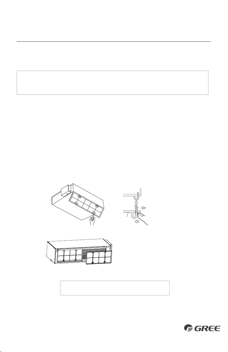
Cleaning
The air filter should be cleaned every 90 days. Cleaning frequency should be increased if the
unit is installed in a room where there is an abnormal amount of dirt and dust.
1. Remove the air filter from the duct.
2. Clean the air filter. Remove dust from the air filter using a vacuum cleaner and gently
rinse in cool water with mild detergent. Don't use hot water to avoid filter shrinking or
deformation. After cleaning the filter, dry filter before replacing.
3. Replace the air filter.
Attach the filter to
the main unit while
pushing down on
the bend clasps.
Main Unit
Force
Force
Filter
Press the air filter downward
into the guided groove. Then
pull the top outward.
NOTE: The 24K size has two separate air filters.
29
Gree Electric Appliances, Inc ©2016
Cat No: GREE_SLIMDUCT_INSTALLATION_120617
GREE ELECTRIC APPLIANCES, INC.
www.greecomfort.com
PRODUCT & INSTALLATION RECORD
For your convenience, please record the model and serial numbers of your new equipment in the
spaces provided. This information, along with the installation data and dealer contact information,
will be helpful should your system require maintenance or service.
UNIT INFORMATION
Outdoor Unit:
Model No.
Serial No.
Indoor Unit:
Model No.
Serial No.
INSTALLATION INFORMATION
Date Installed:
DEALERSHIP/INSTALLER INFORMATION
Company Name:
Address:
Phone Number:
Technician Name: