SAFETY REVERSING SENSOR REPLACEMENT
041-0136 & 041-0155
Be sure power is NOT connected to the garage door opener BEFORE installingthe
safety reversingsensor.
To prevent SERIOUS INJURY or DEATH from closinggarage door:
• Correctly connect andalignthe safety reversingsensor. This required safety
device MUST NOT be disabled.
• Installthe safety reversingsensor so beam is NO HIGHER than 6" (15 cm)
above garage floor.
WARNING: This product can expose you to chemicals including lead, which are
knownto the State of California tocause cancer or birth defects or other
reproductive harm. For more information goto www.P65Warnings.ca.gov
The images throughout this manual are for reference only and your product may look
different.
INSTALL THE SAFETY REVERSING SENSORS
Disconnect power to the garage door opener before you begin.
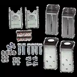
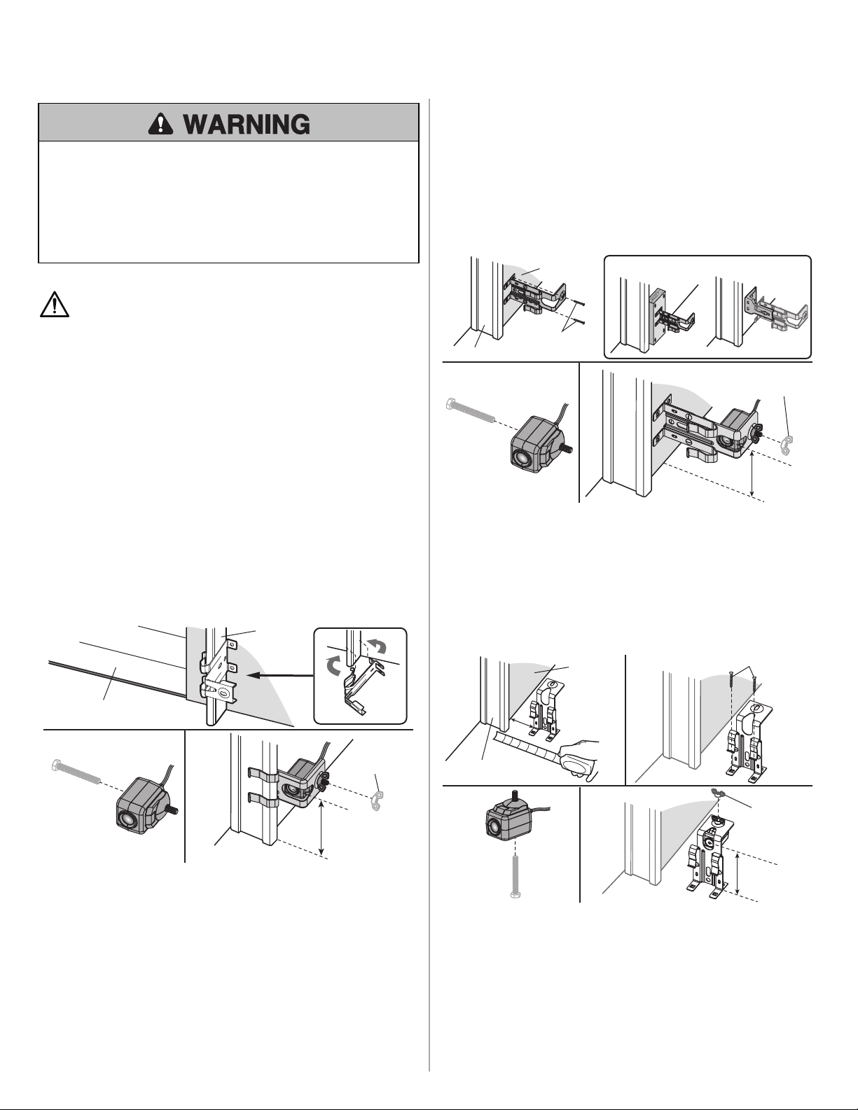
The safety reversingsensors are designed to clipontothe door track with the provided
sensor brackets. If the door track willnot support the sensor bracket a wall installationis
recommended. The sensor beam shouldbe NO HIGHER than 6" (15 cm) above the floor.
DOOR TRACK INSTALLATION
1. Slide the curved arms of the sensor bracket around the edge of the door track.
Snap into place so that the sensor bracket is flush against the track.
2. Slide the hex screw throughthe sensor.
3. Attach the sensor to the bracket with the wingnut. Make sure the lens is not
obstructed by the bracket.
Repeat the steps withthe other sensor on the opposite door track. Bothlenses must
face each other.
6" (15 cm) max.
Door track
1
2
3
Garage door
Wing nut
WALL OPTION
Make sure the brackets on each side are clear of the door track andhave the same
amount of clearance so the sensors willaligncorrectly. If additional clearance is needed,
use extension brackets 041A5281-1 (not provided) or woodblocks.
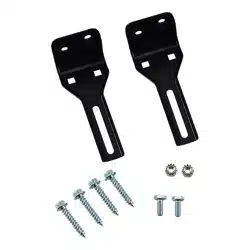
1. Attach the sensor bracket against the wallwithtwo lag screws (not provided).
2. Slide the hex screw throughthe sensor.
3. Attach the sensor to the bracket with the wingnut. Make sure the lens is not
obstructed by the bracket.
Repeat the steps withthe other sensor on the opposite side of the garage door. Both
lenses must face each other.
OR
1
Wing Nut
OPTIONAL
2 3
Door track
Inside
garage wall
6" (15 cm)
max.
Not provided
FLOOR OPTION
1. Measure the position of both sensor brackets so they willbe the same distance
fromthe wall andunobstructed.
2. Attach the bracket to the floor withconcrete anchors (not provided).
3. Slide the hex screw throughthe sensor.
4. Attach the sensor to the bracket with the wingnut. Make sure the lens is not
obstructed by the bracket.
Repeat the steps withthe other sensor on the opposite side of the garage door. Both
lenses must face each other.
1
3
4
2
Inside
garage wall
Not provided
Door track
6" (15 cm) max.
Wingnut
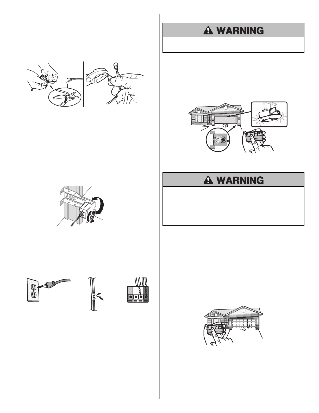
WIRE THE SENSORS
1. Separate the ends of the new sensor wire. Cut any exposed wire downto the
insulation.
2. Usingthe four locking connectors, connect the new wire to the existing wire by
color: white/black to white/black, white to white. NOTE: If installing in a pre-wired
garage, connect the new sensor wires to the same pre-installed wires as the old
sensors. Insert the wire allthe way into the connector. Firmly crimpthe connector
with adjustable pliers. Once crimped, the connector cannot be re-used.
1 2
Reconnect power to the garage door opener.
ALIGN THE SENSORS
IMPORTANT: The safety reversing sensors MUST be connected and aligned
correctly before the garage door opener will move in the down direction.
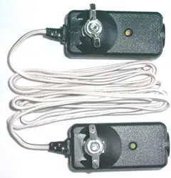
When the garage door opener has power, check the safety reversingsensors. If the
sensors are aligned andwired correctly, both LEDs will glow steadily.
To align the safety reversing sensors:
1. Loosen the wingnuts.
2. Adjust the sensors upor downuntilboth LEDs glow steady indicatingalignment.
3. Tighten the wingnut to secure the sensor.
Wing nut
TROUBLESHOOTING
If either of the sensor LEDs are off, there is no power to the sensor:
1. Check that you have power to the garage door opener.
2. Check the sensor wire is not shorted or broken.
3. Check that the sensors are wired correctly; white wires to white terminal and
white/black wires to grey terminal.
RED
WHITE
WHITE
GREY
3
2
1
If the green receiving sensor LED is blinking, the sensors are obstructed or
misaligned:
1. Check for obstructions inthe sensor light beam.
2. Alignthe sensors.
3. If the receiving sensor (green LED) faces direct sunlight, switch the sensors to
opposite sides of the door toassure proper operation.
TEST THE SENSORS
Without a properly installed safety reversingsensor, persons (particularly small
children) couldbe SERIOUSLY INJURED or KILLED by a closinggarage door.
1. Open the door. Place the garage door opener cartonin the path of the door.
2. Press the remote control push button to close the door. The door will not move more
than 1"(2.5cm), the garage door opener lights willflash 10times, the green LED on
the receiving sensor will blink.
The garage door opener will not close froma remote controlif the sensor light beam is
misaligned or obstructed. If the garage door opener closes the door when the safety
reversingsensor is obstructed (andthe sensors are no more than 6"[15cm] above the
floor), callfor a trained door systems technician.
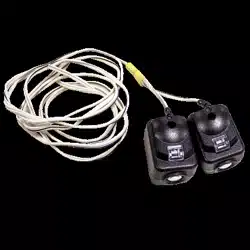
Receiving sensor
Green LED
TEST THE SAFETY REVERSAL SYSTEM
Without a properly installed safety reversal system, persons (particularly small
children) couldbe SERIOUSLY INJURED or KILLED by a closinggarage door.
• Safety reversal system MUST be tested every month.
• After ANY adjustments are made, the safety reversal system MUST be tested.
Door MUST reverse oncontact with1-1/2" (3.8 cm) high object (or 2x4 laidflat)
on the floor.
1. Withthe door fully open, place a 1-1/2inch (3.8 cm) board (or a 2x4 laidflat) onthe
floor, centered under the garage door.
2. Press the remote controlor wall-mounted door controlto close the door. The door
shouldstopand reverse when it makes contact withthe board. The door returns to
the previous open position. Newer model openers will beep andthe lights willflash 5
times to indicate reversal.
3. If the door reverses, remove the board. The test is complete.
If the door stops but does not reverse:
1. Refer to your garage door opener manual andset the down limit closer to the
garage floor. NOTE: On a sectional door, make sure adjustments do not force the
door arm beyond a straight up and down position.
2. Repeat the Safety Reversal test.
If the test continues to fail, calla trained door systems technician.
REMPLACEMENT DU CAPTEUR D’INVERSION DE SÉCURITÉ
041-0136 ET 041-0155
S’assurer que l’ouvre-porte de garage est hors tensionAVANT d’installer le capteur
d’inversionde sécurité.
Pour prévenir des BLESSURES GRAVES ouMORTELLES par suite d’une porte de
garage qui se ferme:
• Raccorder et aligner correctement le capteur d’inversionde sécurité. Ce
dispositif de sécurité obligatoire NE DOIT PAS être désactivé.
• Installer le capteur d’inversionde sécurité de manière à ce que le faisceau NE
SOIT PAS À UNE HAUTEUR de plus de 15cm (6po) au-dessus du plancher du
garage.
AVERTISSEMENT : Ce produit peut vous exposer à des produits chimiques
comme le plomb, reconnupar l’État de la Californie comme cause de cancers,
d’anomalies congénitales et d’autres problèmes liés à la reproduction. Pour plus
d’information, visitez www.P65Warnings.ca.gov
Les illustrations de ce manuel ne sont fournies qu’à titre de référence; votre produit peut
avoir une apparence différente.
INSTALLATION DES CAPTEURS D’INVERSION DE
SÉCURITÉ
Déconnecter l’alimentation à l’ouvre-porte de garage avant de commencer.
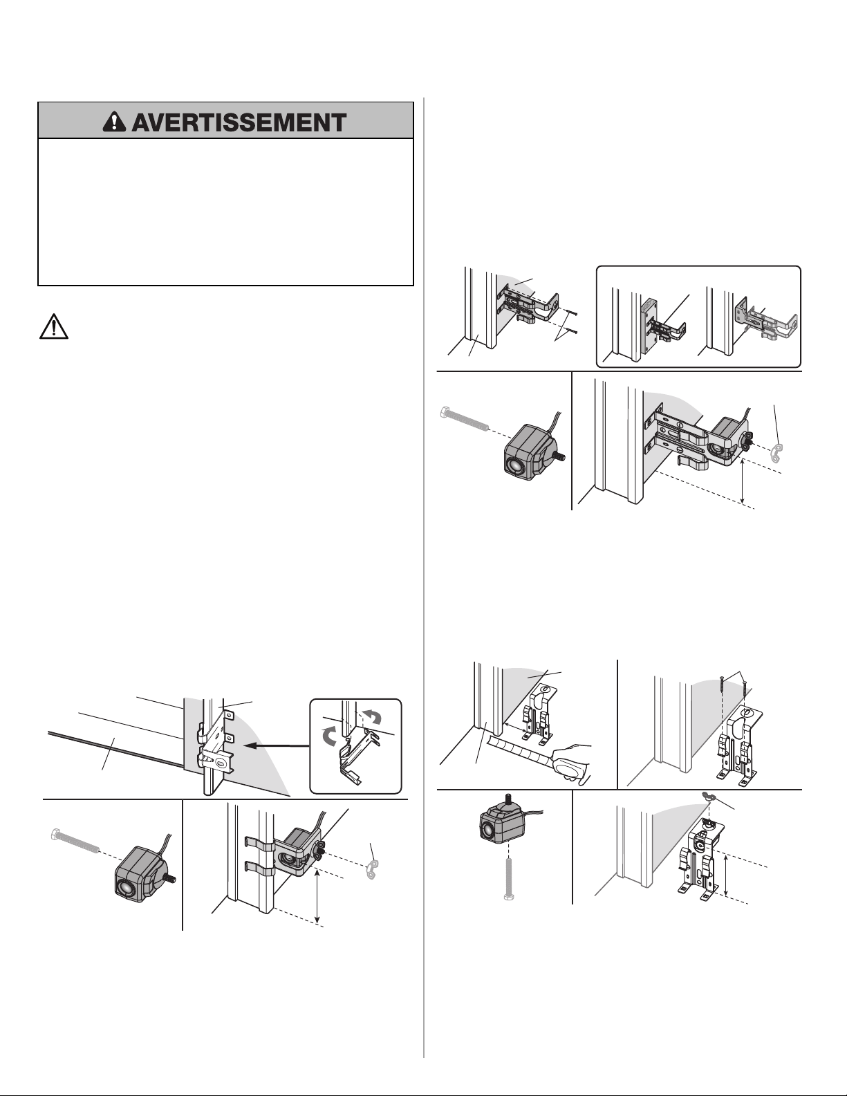
Les capteurs d’inversionde sécurité sont conçus pour s’agrafer sur le guide de la porte
avec les supports de capteur fournis. Si le guide de porte ne supporte pas solidement le
support de capteur, une installationmurale est recommandée. Le faisceau du capteur ne
doit pas être à plus de 15cm (6po) au-dessus dusol.
INSTALLATION DES GUIDES DE PORTE
1. Faire glisser les biellettes courbées dusupport de capteur sur le pourtour du guide
de la porte. Enclencher en place afinque le support de capteur soit abouté contre le
guide.
2. Glisser la vis hexagonale par le capteur.
3. Fixer le capteur au support avec l’écrouà oreilles. S’assurer que la lentille n’est pas
obstruée par le support de capteur.
Répéter ces étapes avec l’autre capteur sur le côté opposé duguide de la porte. Les
deux lentilles doivent faire face l’une à l’autre.
15cm (6po) max.
Guide de
porte
1
2
3
Porte de garage
Écrou à oreilles
OPTION MURALE
S’assurer que les supports de chaque côté sont dégagés duguide de la porte à la même
distance de sorte que les capteurs sont alignés correctement. Si un dégagement
supplémentaire est nécessaire, utiliser les supports de rallonge 041A5281-1 (non
fournis) ou des cales en bois.
1. Fixer le support de capteur contre le mur avec deux tire-fond(nonfournis).
2. Glisser la vis hexagonale par le capteur.
3. Fixer le capteur au support avec l’écrouà oreilles. S’assurer que la lentille n’est pas
obstruée par le support.
Répéter ces étapes avec l’autre capteur sur le côté opposé de la porte de garage. Les
deux lentilles doivent faire face l’une à l’autre.
OU
1
Écrou à oreilles
EN OPTION
2 3
Guide de porte
Mur de garage
à l’intérieur
15cm (6po)
max.
Non fourni
OPTION AU SOL
1. Mesurer soigneusement la position des deux supports de capteurs de sorte qu’ils
seront à la même distance du mur et dégagés.
2. Fixer les supports de capteurs au solavec des ancrages de béton(non fournis).
3. Glisser la vis à tête hexagonale par le capteur.
4. Fixer le capteur au support avec l’écrouà oreilles. S’assurer que la lentille n’est pas
obstruée par le support de capteur.
Répéter ces étapes avec l’autre capteur sur le côté opposé de la porte de garage. Les
deux lentilles doivent faire face l’une à l’autre.
1
3
4
2
Mur de
garage à
l’intérieur
Non fourni
Guide de porte
15cm (6po) max.
Écrou à oreilles
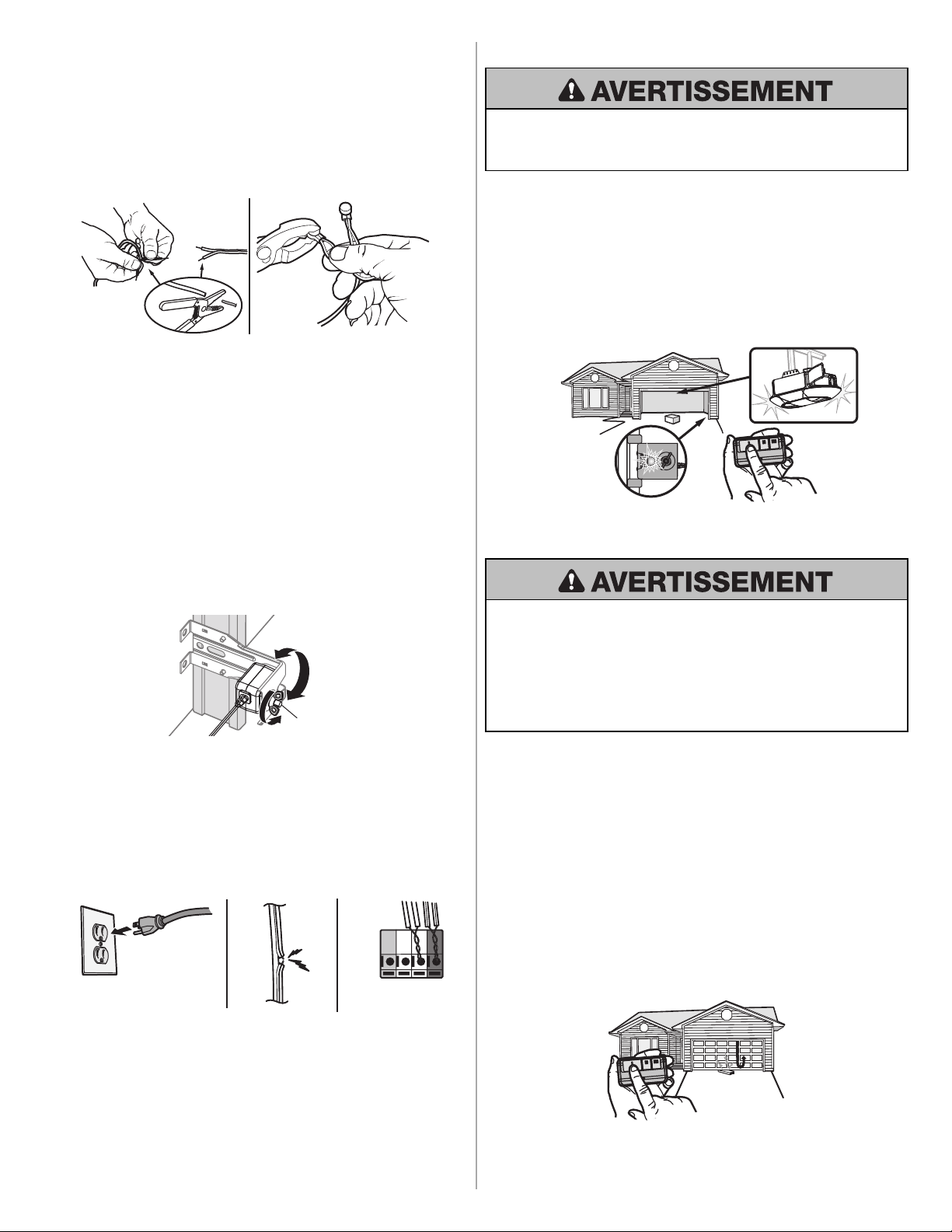
CÂBLAGE DES CAPTEURS
1. Séparer les extrémités dufil ducapteur neuf. Couper tout filexposé jusqu’à la gaine
isolante.
2. Avec quatre connecteurs à verrouillage, connecter le nouveau filau filexistant par
couleur: Blanc/noir à blanc/noir, blanc à blanc. REMARQUE: Pour une
installation dans un garage précâblé, connecter les fils du capteur neuf aux mêmes
fils préinstallés des anciens capteurs. Insérer le fil complètement dans le
connecteur. Sertir fermement le connecteur avec des pinces réglables. Une fois
serti, le connecteur ne peut pas être réutilisé.
1 2
Reconnecter l’alimentation à l’ouvre-porte de garage.
ALIGNER LES CAPTEURS
IMPORTANT: Les capteurs d’inversion de sécurité doivent être connectés et
alignés correctement avant que l’ouvre-porte de garage n’entame le mouvement de
fermeture.
Lorsque l’ouvre-porte dugarage est sous tension, vérifier les capteurs d’inversion de
sécurité. Si les capteurs d’inversionde sécurité sont alignés et câblés correctement, les
deux DELs’allumeront en continu.
Alignement des capteurs d’inversion de sécurité:
1. Desserrer les écrous à oreilles.
2. Régler les capteurs vers le haut oule bas jusqu’à ce que les deux DEL s’allument en
continupour indiquer unbonalignement.
3. Serrer l’écrouà oreilles pour fixer le capteur.
Écrou à oreilles
DÉPANNAGE
Si l’une ou l’autre des DEL des capteurs est éteinte, c’est que le capteur ne reçoit
pas d’alimentation électrique.
1. S’assurer que l’ouvre-porte de garage reçoit bien l’alimentation électrique.
2. Vérifier que le filducapteur n’est pas en court-circuit ourompu.
3. Vérifier que les capteurs sont correctement câblés; les fils blancs à la borne
blanche et les fils blancs/noirs à la borne grise.
ROUGE
BLANC
BLANC
GRIS
3
2
1
Si la DEL verte du capteur récepteur clignote, c’est que les capteurs sont obstrués
ou désalignés:
1. Vérifier si un objet obstrue le faisceau lumineux.
2. Aligner les capteurs.
3. Sile capteur récepteur (DEL verte) fait face directement au soleil, inverser la
position des capteurs de chaque côté de la porte pour assurer unfonctionnement
approprié.
ESSAI DES CAPTEURS
Sans un système d’inversionde sécurité bien installé, des personnes (plus
particulièrement les petits enfants) pourraient être GRIÈVEMENT BLESSÉES ou
TUÉES par une porte de garage qui se referme.
1. Ouvrir la porte. Mettre la boîte en carton de l’ouvre-porte dans la trajectoire de la
porte.
2. Appuyer sur le bouton-poussoir de la télécommande pour fermer la porte. La porte
ne se déplacera pas de plus de 2,5cm (1po), les lampes de l’ouvre-porte de garage
clignoteront 10fois et la DEL verte sur le capteur récepteur clignotera.
Une télécommande d’ouvre-porte n’activera pas la fermeture de la porte du garage si le
faisceau lumineux ducapteur est désaligné ou obstrué. Si l’ouvre-porte de garage ferme
la porte lorsque le capteur d’inversionde sécurité est obstrué (et que les capteurs ne
sont pas à plus de 15cm [6po] dusol), appeler untechnicien formé en systèmes de
porte.
Capteur récepteur
DEL verte
ESSAI DU SYSTÈME D’INVERSION DE SÉCURITÉ
Sans un système d’inversionde sécurité bien installé, des personnes (plus
particulièrement les petits enfants) pourraient être GRIÈVEMENT BLESSÉES ou
TUÉES par une porte de garage qui se referme.
• Le système d’inversionde sécurité DOIT être testé chaque mois.
• Après avoir effectué QUELQUE réglage que ce soit, on DOIT faire l’essai du
système d’inversionde sécurité. La porte de garage DOIT remonter au contact
d’un objet d’une hauteur de 3,8cm (11/2de po) (ouun2 x 4 posé à plat) dusol.
1. La porte étant entièrement ouverte, placer une planche de 3,8cm (11/2de po)
d’épaisseur (ouun2 x 4 à plat) sur le sol, centrée sous la porte de garage.
2. Appuyer sur le boutonde la télécommande ou de la commande de porte montée au
mur pour fermer la porte. La porte devrait s’arrêter et remonter quandelle entre en
contact avec la planche. La porte retourne à la positiond’ouverture précédente. Les
ouvre-portes de modèles plus récents émettront des bips et les lampes
clignoteront 5fois pour indiquer l’inversionde la course de la porte.
3. Sila porte inverse sa course, retirer la planche. Le test est terminé.
Si la porte arrête sa course, mais ne l’inverse pas:
1. Consulter le manuel de votre ouvre-porte de garage et régler la limite de fermeture
plus près dusoldu garage. REMARQUE: Dans le cas d’une porte articulée,
s’assurer que les réglages ne forcent pas la biellette au-delà d’une position
d’ouverture ou de fermeture.
2. Répéter l’essai du système d’inversionde sécurité.
Si l’essai échoue encore, appeler untechnicien formé en systèmes de porte.
REPUESTO DEL SENSOR DE REVERSA DE SEGURIDAD
041-0136 Y 041-0155
Asegúrese de que la energía eléctrica NO esté conectada al abre-puertas de garaje
ANTES de instalar los sensores de reversa de seguridad.
Para evitar la posibilidad de sufrir una LESIÓN GRAVE o LA MUERTE cuando la
puerta del garaje se esté cerrando:
• Conecte correctamente y verifique la alineación de los sensores de reversa de
seguridad. Este dispositivo de seguridad es necesarioy NO se DEBEdesactivar.
• Instale el sensor de reversa de seguridad de modoque el haz NO SUPERE 15 cm
(6 pulg.) sobre el nivel del piso.
ADVERTENCIA: Este producto puede exponerle a productos químicos (incluido
el plomo), que a consideración del estadode California causan cáncer, defectos
congénitos u otros daños reproductivos. Para obtener más información, visite
www.P65Warnings.ca.gov
Las imágenes en este manual se usan solamente como referencia. El producto
comprado podría tener un aspecto diferente.
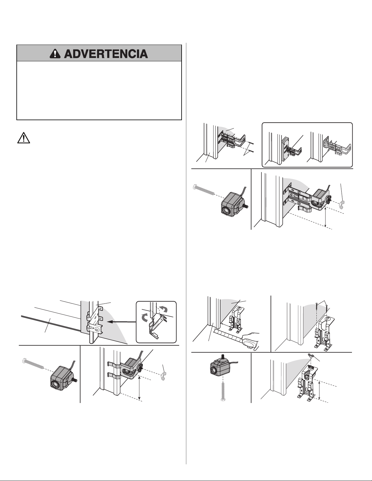
INSTALAR LOS SENSORES DE REVERSA DE
SEGURIDAD
Desconecte la alimentación eléctrica al abre-puertas de garaje antes de comenzar.
Los sensores de reversa de seguridad están diseñados para ser colocados en el riel de
la puerta conlas ménsulas proporcionadas. Si la ménsula del sensor no se ajusta al riel
de la puerta, es mejor instalarla sobre la pared. Elhaz del sensor NO DEBEESTAR A
MÁS DE 15cm (6 pulg.) por encima del piso.
INSTALACIÓN EN EL RIEL DE LA PUERTA
1. Deslice los brazos curvos de la ménsula del sensor alrededor del borde del riel de la
puerta. Colóquelos en su posición de modoque la ménsula del sensor quede a ras
del riel.
2. Deslice el tornillohexagonal a través del sensor.
3. Sujete el sensor a la ménsula conla tuerca de mariposa. Asegúrese de que la
ménsula no obstruya la lente.
Repita los pasos conel otro sensor en el riel de puerta opuesto. Las dos lentes deben
quedar enfrentadas.
15 cm (6 pulg.)
como máx.
Riel de la
puerta
1
2
3
Puerta de garaje
Tuerca de
mariposa
OPCIÓN DE PARED
Asegúrese de que las ménsulas de cada ladonoqueden obstaculizadas por los rieles de
la puerta y tengan el mismoespaciolibre para que los sensores se alineen
correctamente. Si fuera necesario más espacio, use ménsulas de extensión041A5281-
1 (no provistas) o bloques de madera.
1. Sujete la ménsula del sensor a la pared condos tornillos para madera (no
provistos).
2. Deslice el tornillohexagonal a través del sensor.
3. Sujete el sensor a la ménsula conla tuerca de mariposa. Asegúrese de que la
ménsula no obstruya la lente.
Repita los pasos conel otro sensor en el ladoopuesto de la puerta de garaje. Los dos
sensores deben quedar frente a frente.
O
1
Tuerca de mariposa
OPCIONAL
2 3
Riel de la puerta
Interior de la
pared de garaje
15 cm (6 pulg.)
como máx.
No incluido
OPCIÓN DE PISO
1. Mida la posiciónde ambas ménsulas del sensor para que estén a la misma distancia
de la pared sin obstáculos en el medio.
2. Sujete las ménsulas al piso con anclajes para hormigón (no provistos).
3. Deslice el tornillohexagonal a través del sensor.
4. Sujete el sensor a la ménsula conla tuerca de mariposa. Asegúrese de que la
ménsula no obstruya la lente.
Repita los pasos conel otro sensor en el ladoopuesto de la puerta de garaje. Las dos
lentes deben quedar enfrentadas.
1
3
4
2
Interior de
la pared de
garaje
No incluido
Riel de la puerta
15 cm (6 pulg.)
como máx.
Tuerca de mariposa
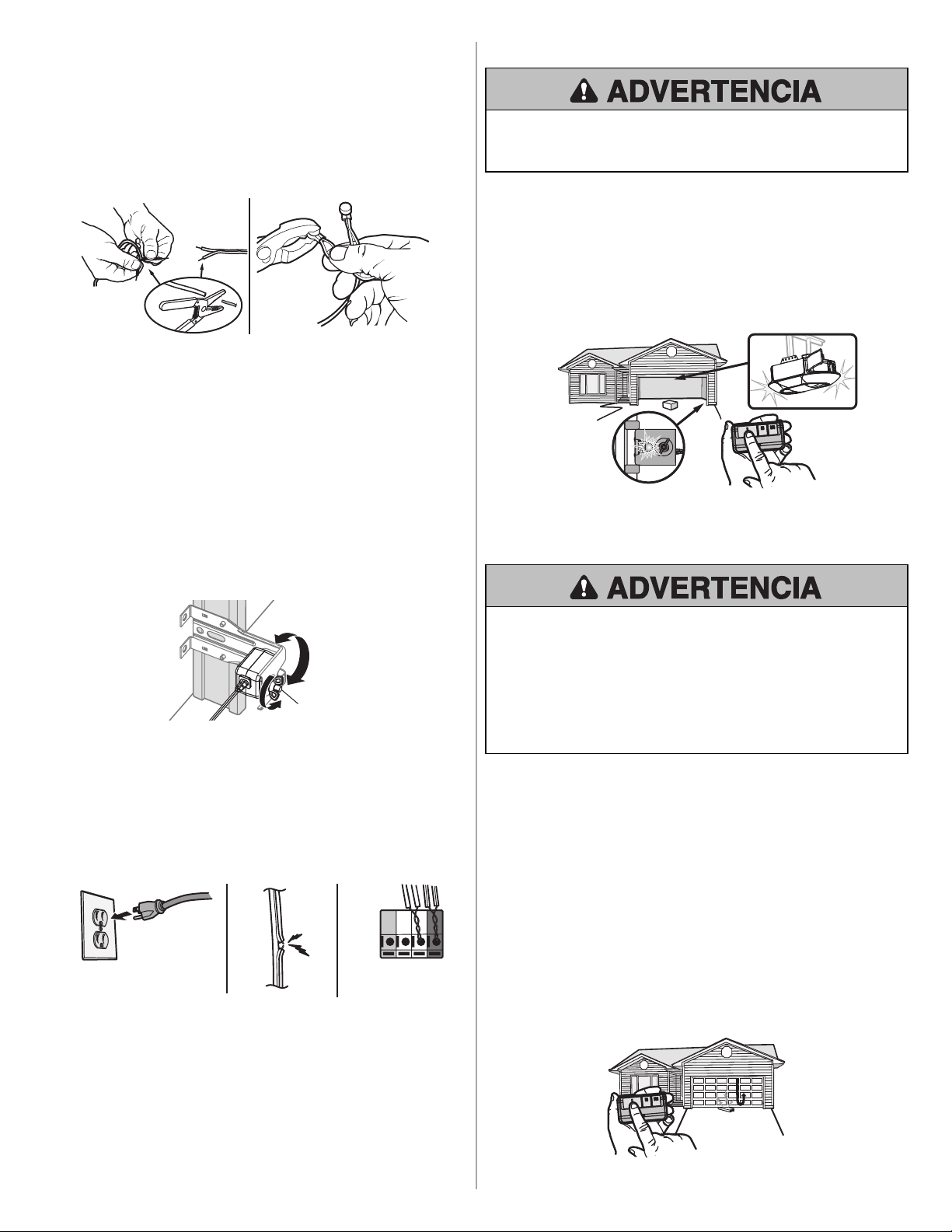
CONECTAR LOS SENSORES
1. Separe los extremos del cable del sensor nuevo. Corte cualquier cable expuesto
hasta el aislamiento.
2. Utilizando los cuatro conectores de fijación, conecte el cable nuevo al cable
existente por color: blanco/negro a blanco/negro, blanco a blanco NOTA: Si realiza
la instalación en un garaje precableado, conecte los cables del sensor nuevo a los
mismos cables preinstalados que los sensores viejos. Introduzca el cable en el
conector. Encastre el conector utilizandopinzas ajustables. Elconector nose puede
volver a utilizar una vez que ha sidoencastrado.
1 2
Vuelva a conectar la alimentación eléctrica al abre-puertas del garaje.
ALINEAR LOS SENSORES
IMPORTANTE: Los sensores de reversa de seguridad deben estar bien conectados y
alineados antes de que el abre-puertas de garaje se mueva hacia abajo.
Cuandoel abre-puertas de garaje tenga energía eléctrica, revise los sensores de
reversa de seguridad. Silos sensores están alineados y conectados correctamente, los
dos LED quedarán encendidos en forma continua.
Cómo alinear los sensores de reversa de seguridad:
1. Afloje las tuercas mariposa.
2. Ajuste los sensores hacia arriba o hacia abajo hasta que ambos LED queden
encendidos en forma continua, loque indica que están alineados.
3. Ajuste la tuerca mariposa para fijar el sensor.
Tuerca de mariposa
RESOLUCIÓN DE PROBLEMAS
Si alguno de los LED de los sensores está apagado, significa que el sensor no tiene
energía.
1. Verifique que el abre-puertas de garaje tenga alimentación.
2. Verifique que el cable del sensor notenga uncortocircuitoniesté roto.
3. Verifique que los sensores estén cableados correctamente; cables blancos a la
terminal blanca y cables banco/negro a la terminal gris.
ROJO
BLANCO
BLANCO
GRIS
3
2
1
Si el LED verde del sensor receptor parpadea, los sensores están obstruidos o
desalineados:
1. Verifique si hay una obstrucciónen el haz de luz del sensor.
2. Alinee los sensores.
3. Siel sensor receptor (LED verde) queda orientadoa la luz solar directa, cambie los
sensores a los lados opuestos de la puerta para garantizar unfuncionamiento
adecuado.
PROBAR LOS SENSORES
Si un sensor de reversa de seguridad nose ha instaladoadecuadamente, las
personas (y los niños pequeños en particular) podrían sufrir LESIONES GRAVES o
incluso MORIR al cerrar la puerta del garaje.
1. Abra la puerta. Coloque la caja del abre-puertas de garaje en el recorrido de la
puerta.
2. Presione el botón pulsador delcontrolremotopara cerrar la puerta. La puerta no se
moverá más de 2.5 cm (1 pulg.), las luces del abre-puertas de garaje parpadearán
10 veces, el LED verde del sensor receptor parpadeará.
El abre-puertas de garaje nopodrá cerrar desde uncontrolremoto si el haz de luz del
sensor está desalineado u obstruido. Si el abre-puertas de garaje cierra la puerta
cuandoestá obstruido el sensor de reversa de seguridad (y los sensores están a nomás
de 6 pulgadas (15cm) por encima del suelo), llame a un técnico de sistemas de puertas.
Sensor receptor
LED verde
PROBAR EL SISTEMA DE REVERSA DE
SEGURIDAD
Si el sistema de reversa de seguridad nose ha instalado adecuadamente, las
personas (y los niños pequeños en particular) podrían sufrir LESIONES GRAVES o
incluso MORIR al cerrar la puerta del garaje.
• Elsistema de reversa de seguridad SE DEBE probar cada mes.
• Después de llevar a cabo CUALQUIER ajuste, SE DEBEprobar el sistema de
reversa de seguridad. La puerta DEBEretroceder al entrar en contacto con un
objeto de 3.8 cm (1 1/2 de pulg.) de altura (o de 5x 10 cm [2 x 4 pulg.] acostado
en el piso).
1. Conla puerta completamente abierta, coloque una tabla de 3.8 cm (1 1/2 de pulg.)
de altura (o de 5x 10cm [2 x 4 pulg.] acostada en el piso), centrada debajode la
puerta del garaje.
2. Presione el controlremotoo el controlde la puerta montado en la pared para cerrar
la puerta. La puerta debería detenerse y retroceder al hacer contacto conla tabla.
Luego debería volver a la posiciónabierta anterior. Los modelos más nuevos de los
abre-puertas emitirán una señalsonora y las luces parpadearán 5 veces para
indicar el retroceso.
3. Sila puerta retrocede, retire la tabla. La prueba está completa.
Si la puerta se detiene pero noretrocede:
1. Consulte el manual de su abre-puertas de garaje y configure el límite más cercano
al piso del garaje. NOTA: Si su puerta es seccionada, asegúrese de que los ajustes
no hagan que el brazo de la puerta se mueva más allá de una posición recta hacia
arriba y hacia abajo.
2. Repita la prueba de reversa de seguridad.
Si la prueba sigue fallando, llame a untécnico capacitadoen sistemas de puertas.


114-5568-000
© 2021, The Chamberlain Group, Inc.
All Rights Reserved
Tous droits réservés
Todos los derechos reservados
The Chamberlain Group, Inc.
300 Windsor Drive
Oak Brook, IL 60523