Loading ...
Loading ...
Loading ...
CONNECTING THE BATTERY CABLES Checking Tire Pressure
Batteryposts,terminals,and relatedaccessoriescontainleadand
leadcompounds,chemicalsknownto the Stateof Californiato cause
cancerand reproductiveharm.Washhandsafterhandling.
Whenattachingbatterycables,alwaysconnectthe POSiTiVE(Red)
wire to its terminalfirst, followedbythe NEGATIVE(Black)wire.
Toconnectthe batterycables,proceedas follows:
NOTE:The positivebatteryterminalis markedPositive(+).The
negativebatteryterminalis markedNegative(-).
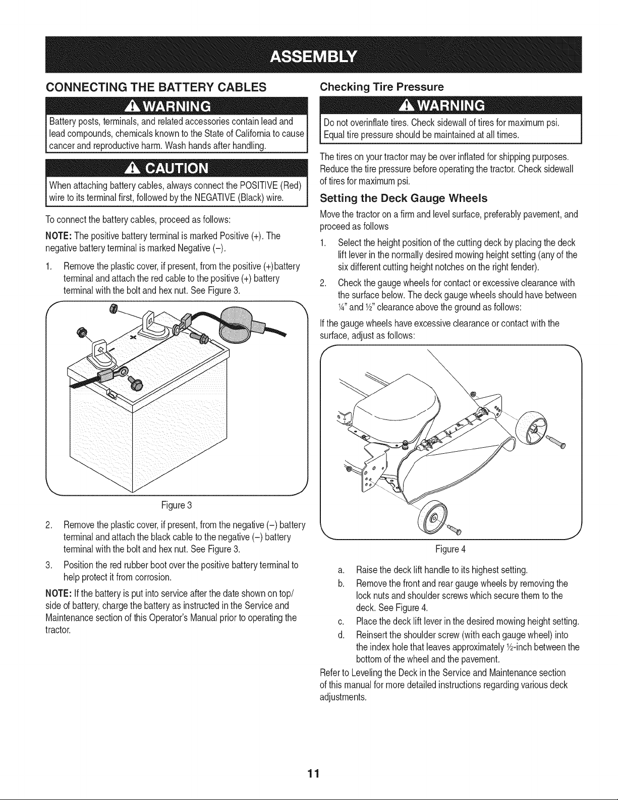
1. Removetheplasticcover,if present,fromthe positive(+)battery
terminaland attachthe redcable to the positive(+)battery
terminalwith the bolt andhex nut.See Figure3.
Figure3
2. Removetheplasticcover,if present,fromthe negative(-) battery
terminaland attachthe black cableto the negative(-) battery
terminalwith the bolt andhex nut.See Figure3.
3. Positionthe redrubberbootoverthe positivebatteryterminalto
helpprotectit fromcorrosion.
NOTE: Ifthe batteryis put intoserviceafterthe dateshownontop/
sided battery,chargethe batteryas instructedinthe Serviceand
Maintenancesectionof this Operator'sManualpriorto operatingthe
tractor.
Donot overinflatetires.Checksidewallof tires for maximumpsi.
Equaltire pressureshouldbe maintainedat all times.
The tiresonyourtractormay beoverinflatedfor shippingpurposes.
Reducethe tire pressurebeforeoperatingthe tractor.Checksidewall
of tiresfor maximumpsi.
Setting the Deck Gauge Wheels
Movethe tractoron afirm and levelsurface,preferablypavement,and
proceedas follows
1. Selectthe heightpositionof the cuttingdeck by placingthe deck
liftleverin the normallydesiredmowingheightsetting(anyof the
sixdifferentcuttingheightnotchesonthe rightfender).
2. Checkthe gaugewheelsfor contactor excessiveclearancewith
the surfacebelow.The deck gaugewheelsshouldhavebetween
1A"and 1/2"clearanceabovethe groundas follows:
Ifthe gaugewheelshaveexcessiveclearanceor contactwiththe
surface,adjustas follows:
f
Figure4
a. Raisethe decklift handleto its highestsetting.
b. Removethe frontand reargaugewheelsby removingthe
locknutsand shoulderscrewswhichsecurethemto the
deck. SeeFigure4.
c. Placethe decklift leverin the desiredmowingheightsetting.
d. Reinsertthe shoulderscrew(witheachgaugewheel)into
the indexholethatleavesapproximately_/2-inchbetweenthe
bottomof the wheeland the pavement.
Referto Levelingthe Deckin the Serviceand Maintenancesection
of this manualfor moredetailedinstructionsregardingvariousdeck
adjustments.
11
Loading ...
Loading ...
Loading ...