
perator s
P R 0 F E S S I 0 N A
LAWN TRACTOR
26 HP, 50" Tractor
Electric Start
PYT9000
Model No. 247.28981
• EspaSol, p. 62
This product has a low emission engine which operates differently
from previously built engines. Before you start the engine, read and
understand this Operator's Manual.
iMPORTANT:
Read and follow all Safety
Rules and instructions before
operating this equipment.
For answers to your questions about
this product, Call:
1=800=659=5917
Craftsman Tractor Help Line
5am = 5 pro, Mort =Sat
Sears Brands Management Corp., Hoffman Estates, IL 60179 U.S.A.
Visit our website: www.craftsman.com FormNo.769-05600
(January27,2010)
Warranty Statement .......................................................... 2
Safety instructions ............................................................ 3
Safety Labels .................................................................... 9
Assembly ......................................................................... 10
Know your Lawn Mower .................................................. 13
Operation ........................................................................ 16
CRAFTSMAN PROFESSIONAL FULL WARRANTY
Whenoperatedand maintainedaccordingto allsuppliedinstructions,ifany non-expendablepartof thisridingequipmentfailsdue to a defectin
materialor workmanshipwithintwo yearsfrom thedate orpurchase,call 1-800-659-5917to arrangefor free in-homerepair.
Theframeand frontaxle will be repairedfreeof chargefor five yearsfromthe dateof purchaseif defectivein materialor workmanship.
Allof the abovewarrantycoverageappliesfor onlyone yearfromthedateof purchaseif this ridingequipmentis everusedfor commercialor
rentalpurposes.
in allcases, if repairprovesimpossible,the ridingequipmentwill be replacedfree of chargewiththe sameoran equivalentmodel.
The batterywill be replacedfree of chargefor 90 daysfrom the dateof purchaseif defectivein materialorworkmanship(ourtestingprovesthat it
will notholda charge).
ThiswarrantycoversONLYdefectsin materialandworkmanship.Searswill NOTpayfor:
• Expendableitemsthatbecomewornduringnormaluse, includingbutnot limitedto blades,spark plugs,aircleaners,belts,and oil filters.
• Standardmaintenanceservicing,oilchanges,or tune-ups.
Tire replacementor repaircausedby puncturesfromoutsideobjects,suchas nails,thorns,stumps,or glass.
Tireor wheelreplacementor repairresultingfromnormalwear,accident,or improperoperationor maintenance.
Repairsnecessarybecauseof operatorabuse, includingbutnot limitedto damagecausedby towingobjectsbeyondthe capabilityof the
ridingequipment,impactingobjectsthatbend theframeor crankshaft,or over-speedingthe engine.
• Repairsnecessarybecauseof operatornegligence,includingbut not limitedto,electricaland mechanicaldamagecausedby improper
storage,failureto usethe propergradeandamountof engineoil, failureto keepthe deckclearof flammabledebris,or failureto maintainthe
ridingequipmentaccordingto the instructionscontainedin theoperator'smanual.
• Engine(fuelsystem)cleaningor repairscausedbyfuel determinedto becontaminatedoroxidized(stale).in general,fuel shouldbe used
within30 daysof itspurchasedate.
Normaldeteriorationandwearof the exteriorfinishes,or productlabelreplacement.
Thiswarrantyappliesonly whilethisproductis withinthe UnitedStates.
Thiswarrantygivesyou specificlegal rights,andyou mayalso haveotherrightswhich varyfrom stateto state.
Sears, Roebuck and Co., Hoffman Estates, IL 60179
GrossHP: 26
EngineOil: SAE30
Fuel: UnleadedGasoline
SparkPlug: Champion®RC12YC
Engine: Briggs& StrattonProfessionalSeries
Model Number
Serial Number
Dateof Purchase
Recordthe modelnumber,serialnumber,
anddateof purchaseabove.
© SearsBrands,LLC 2
Thissymbolpointsout importantsafetyinstructionswhich,if not
followed,couldendangerthepersonalsafetyand/orpropertyof
yourselfandothers. Readand followall instructionsin thismanual
beforeattemptingto operatethis machine.Failureto complywith
theseinstructionsmay resultin personalinjury.Whenyou seethis
symbol,HEEDITSWARNING!
CALIFORNIA PROPOSITION 65
EngineExhaust,someof itsconstituents,andcertainvehicle
componentscontainoremitchemicalsknownto Stateof California
to causecancerandbirthdefects orother reproductiveharm.
Batteryposts,terminals,and relatedaccessoriescontainlead and
leadcompounds,chemicalsknownto the Stateof Californiato
causecancerand reproductiveharm.Washhandsafterhandling.
Thismachinewas builtto be operatedaccordingto the safeopera-
tion practicesinthis manual.As withanytype of powerequipment,
carelessnessorerror on the partof the operatorcan resultin serious
injury.Thismachineis capableof amputatingfingers,hands,toes
andfeet andthrowingdebris.Failureto observethe followingsafety
instructionscouldresultin seriousinjuryor death.
Your Responsibility--Restrict the useof this powermachineto
personswho read,understandandfollow thewarningsand instruc-
tionsin this manualandon the machine.
SAVE THESE INSTRUCTIONS!
GENERAL OPERATION
• Read,understand,andfollowall instructionson the machineand
in themanual(s)beforeattemptingto assembleand operate.
Keepthis manualina safe placefor futureand regularreference
andfor orderingreplacementparts.
• Befamiliarwith all controlsandtheir properoperation.Knowhow
to stopthe machineanddisengagethemquickly.
• Neverallowchildrenunder14yearsoldto operatethis machine.
Children14yearsold andover shouldreadandunderstandthe
operationinstructionsandsafety rulesinthis manualandshould
betrainedand supervisedbya parent.
• Neverallowadultsto operatethis machinewithoutproper
instruction.
• Tohelpavoidbladecontactor a thrownobjectinjury,keep
bystanders,helpers,childrenandpets at least75feet fromthe
machinewhile it is in operation.Stopmachineif anyoneenters
the area.
• Thoroughlyinspectthe area wherethe equipmentis to be used.
Removeallstones,sticks,wire, bones,toys,andotherforeign
objectswhichcouldbe pickedup andthrownby the blade(s).
Thrownobjectscan causeseriouspersonalinjury.
• Planyour mowingpatternto avoiddischargeof materialtoward
roads,sidewalks,bystandersandthe like.Also, avoiddischarg-
ingmaterialagainsta wall or obstructionwhichmaycause
dischargedmaterialto ricochetbacktowardthe operator.
• Alwayswear safetyglassesor safetygogglesduringoperation
andwhile performingan adjustmentor repairto protectyoureyes.
Thrownobjectswhichricochetcancause seriousinjuryto the
eyes.
• Wearsturdy,rough-soledworkshoesand close-fittingslacksand
shirts.Loosefittingclothesandjewelry canbe caughtin movable
parts.Neveroperatethismachineinbarefeet orsandals.
• Beawareof the mowerandattachmentdischargedirectionand
do not pointit at anyone.Donot operatethe mowerwithoutthe
dischargecoveror entiregrasscatcherin its properplace.
Donot put handsor feet nearrotatingpartsor underthe cutting
deck. Contactwiththe blade(s)can amputatehandsandfeet.
A missingor damageddischargecovercan causeblade contact
or thrownobjectinjuries.
• Stoptheblade(s)whencrossinggraveldrives,walks,or roads
andwhile notcuttinggrass.
• Watchfor trafficwhenoperatingnearor crossingroadways.This
machineis not intendedfor useon any public roadway.
• Donot operatethe machinewhile underthe influenceof alcohol
or drugs.
• Mowonly in daylightorgood artificiallight.
Nevercarrypassengers.
• Disengageblade(s)beforeshiftinginto reverse.Backup slowly.
Alwayslookdownandbehindbeforeandwhile backingto avoida
back-overaccident.
3
• Slowdownbeforeturning.Operatethe machinesmoothly.Avoid
erraticoperationandexcessivespeed.
Disengageblade(s),setparkingbrake,stopengineand waituntil
the blade(s)cometo a completestopbeforeremovinggrass
catcher,emptyinggrass,uncloggingchute,removinganygrassor
debris,or makinganyadjustments.
Neverleavea runningmachineunattended.Alwaysturnoff
blade(s),setparkingbrake,stopengine andremovekeybefore
dismounting.
Useextracare whenloadingorunloadingthe machineintoa
trailerortruck. Thismachineshouldnot bedrivenup or down
ramp(s),becausethe machinecouldtip over,causingserious
personalinjury.The machinemustbe pushedmanuallyon
ramp(s)to loador unloadproperly.
Mufflerandengine becomehotandcan causea burn.Do not
touch.
Checkoverheadclearancescarefullybeforedrivingunderlow
hangingtree branches,wires,dooropeningsetc.,wherethe
operatormaybe struckor pulledfromthe machine,whichcould
resultin seriousinjury.
Disengageallattachmentclutchesanddepressthe brakepedal
completelybeforeattemptingto start engine.
Yourmachineisdesignedto cutnormalresidentialgrassof a
heightnomorethan 10".Do not attemptto mowthroughunusually
tall,dry grass(e.g.,pasture)or piles of dry leaves.Drygrass or
leavesmaycontactthe engineexhaustand/or buildupon the
mowerdeckpresentinga potentialfire hazard.
Useonlyaccessoriesand attachmentsapprovedfor this machine
by the machinemanufacturer.Read,understandand followall
instructionsprovidedwiththe approvedaccessoryor attachment.
Fora list of approvedaccessoriesand attachments,call 1-800-
659-5917.
Dataindicatesthat operators,age60 yearsand above,are
involvedin a largepercentageof riding mower-relatedinjuries.
Theseoperatorsshouldevaluatetheirabilityto operatethe riding
mowersafelyenoughto protectthemselvesandothersfrom
seriousinjury.
If situationsoccurwhicharenot coveredinthis manual,usecare
andgoodjudgment.Contact1-800-659-5917for informationand
assistance.
SLOPE OPERATION
Slopesarea majorfactorrelatedto loss of controland tip-over
accidentswhichcan resultinsevereinjuryor death.All slopesrequire
extracaution.If youcannotback upthe slopeor if youfeel uneasyon
it, do not mowit.
Foryoursafety,use the SlopeGuide includedas partof this manual
to measureslopesbeforeoperatingthis machineona slopedor hilly
area. Ifthe slopeis greaterthan15 degreesas shownonthe Slope
Guide,do notoperatethis machineonthatarea or seriousinjurycould
result.
Do:
o
Mowupand down slopes,not across.Exerciseextremecaution
whenchangingdirectionon slopes.
• Watchfor holes,ruts,bumps,rocks,orother hiddenobjects.
Uneventerraincouldoverturnthe machine.Tallgrass can hide
obstacles.
Useslowspeed.Choosea lowenoughspeedsettingso that
you will nothaveto stopor shiftwhileon the slope.Tiresmay
lose tractionon slopeseventhoughthe brakesarefunctioning
properly.Alwayskeepmachinein gearwhen goingdownslopes
to takeadvantageof enginebrakingaction.
• Followthe manufacturer'srecommendationsfor wheelweights
or counterweightsto improvestability.Forrecommendations,call
1-800-659-5917.
• Useextracarewithgrass catchersor otherattachments.These
can changethe stabilityof the machine.
Keepallmovementonthe slopesslowand gradual.Do not make
suddenchangesinspeedor direction.Rapidengagementor
brakingcouldcausethe frontof the machineto lift and rapidlyflip
overbackwardswhich couldcauseseriousinjury.
• Avoidstartingorstoppingon a slope.If tireslosetraction,disen-
gagethe blade(s)andproceedslowlystraightdownthe slope.
DoNot:
• Donot turnon slopesunlessnecessary;then,turnslowlyand
graduallydownhill,if possible.
• Donot mow neardrop-offs,ditchesor embankments.The mower
could suddenlyturnover if a wheelis overthe edgeof a cliff,
ditch,or if an edgecavesin.
• Donot try to stabilizethe machineby puttingyourfooton the
ground.
• Donot usea grass catcheron steepslopes.
• Donot mowon wet grass.Reducedtractioncouldcausesliding.
• Donot attemptto coastdownhill.Over-speedingmaycausethe
operatorto lose controlof the machineresultingin seriousinjury
or death.
• Donot tow heavypull behindattachments(e.g.loadeddumpcart,
lawn roller,etc.)on slopesgreaterthan5 degrees.Whengoing
down hill,the extraweighttends to pushthe tractorand may
causeyou to loosecontrol.(e.g.tractormay speedup,braking
and steeringabilityare reduced,attachmentmayjack-knifeand
causetractorto overturn).
4
CHILDREN
Tragicaccidentscanoccur ifthe operatoris notalert to the presence
of children.Childrenare oftenattractedto the machineandthe mowing
activity.They do notunderstandthe dangers.Neverassumethat
childrenwill remainwhereyou last sawthem.
• Keepchildrenout of the mowingareaand inwatchfulcare of a
responsibleadultotherthanthe operator.
• Bealert andturnmachineoff ifa childentersthe area.
• Beforeandwhilebacking,lookbehindanddownfor small
children.
Nevercarrychildren,evenwith the blade(s)shutoff.Theymay
fall offandbe seriouslyinjuredorinterferewith safemachine
operation.
• Useextremecarewhenapproachingblind corners,doorways,
shrubs,treesor otherobjectsthatmay blockyourvisionof a child
whomayrun intothe machine.
Toavoidback-overaccidents,alwaysdisengagethe cutting
blade(s)beforeshiftingintoReverse.If equipped,the "Reverse
CautionMode"(bladesoperatewhilemachineridesin reverse)
shouldnotbe usedwhenchildrenor othersarearound.
Keepchildrenawayfrom hotor runningengines.They cansuffer
burnsfroma hotmuffler.
• Removekeywhenmachineisunattendedto preventunauthorized
operation.
Neverallowchildrenunder14 yearsof ageto operatethis machine.
Children14and overshouldreadandunderstandthe instructionsand
safeoperationpracticesin thismanualandon the machineandshould
betrainedand supervisedbyan adult.
TOWING
Towonlywitha machinethat hasa hitchdesignedfor towing.Do
not attachtowedequipmentexceptat the hitch point.
Followthe manufacturersrecommendationforweightlimitsfor
towedequipmentand towingonslopes.For recommendations,
call 1-800-659-5917.
Neverallowchildrenor othersinor on towedequipment.
Onslopes,theweightof thetowed equipmentmaycause lossof
tractionandloss of control.
Alwaysuseextracautionwhentowingwith a machinecapableof
makingtightturns (e.g."zero-turn"ride-onmower). Makewide
turnsto avoidjack-knifing.
Travelslowlyand allowextradistanceto stop.
Do notcoastdownhill.
SERVICE
SafeHandlingof Gasoline
Toavoidpersonalinjuryorpropertydamageuse extremecarein
handlinggasoline.Gasolineisextremelyflammableandthe vaporsare
explosive.Seriouspersonalinjurycanoccurwhengasolineis spilled
on yourselforyour clotheswhich can ignite.Washyourskinand
changeclothesimmediately.
• Useonly an approvedgasolinecontainer.
Neverfill containersinsidea vehicleoron a truckortrailer bed
witha plasticliner.Alwaysplacecontainerson the groundaway
fromyourvehiclebeforefilling.
Whenpractical,removegas-poweredequipmentfromthe truck
or trailerandrefueliton theground.If this isnot possible,then
refuelsuchequipmentona trailerwitha portablecontainer,rather
than froma gasolinedispensernozzle.
Keepthe nozzleincontactwiththe rim of the fueltank or
containeropeningat all timesuntilfuelingiscomplete.Donot use
a nozzlelock-opendevice.
Extinguishall cigarettes,cigars,pipesandothersourcesof
ignition.
• Neverfuel machineindoors.
Neverremovegascap or addfuelwhilethe engineis hotor run-
ning.Allowengineto coolat leasttwo minutesbeforerefueling.
Neveroverfill fuel tank. Filltankto no morethan 1/2inchbelow
bottomof filler neckto allowspaceforfuel expansion.
• Replacegasolinecap andtightensecurely.
• Ifgasolineis spilled,wipeitoff the engineandequipment.Move
machineto anotherarea.Wait5 minutesbeforestartingthe
engine.
• To reducefire hazards,keepmachinefree of grass,leaves,or
otherdebrisbuild-up.Cleanup oilor fuel spillageand removeany
fuel soakeddebris.
• Neverstorethe machineor fuelcontainerinsidewherethere isan
openflame,sparkor pilotlight as ona waterheater,spaceheater,
furnace,clothesdryeror othergasappliances.
Allowa machineto coolat leastfive minutesbeforestoring.
GeneralService
• Neverrunanengineindoorsorinapoorlyventilatedarea.Engine
exhaustcontainscarbonmonoxide,anodorless,anddeadlygas.
• Beforecleaning,repairing,orinspecting,makecertainthe
blade(s)andallmovingpartshavestopped.Disconnectthespark
plugwireandgroundagainsttheenginetopreventunintended
starting.
• Periodicallychecktomakesurethebladescometocomplete
stopwithinapproximately(5)fivesecondsafteroperatingthe
bladedisengagementcontrol.Ifthebladesdonotstopwithinthe
thistimeframe,yourmachineshouldbeservicedprofessionally
byaSearsorotherqualifiedservicedealer.
• Checkbrakeoperationfrequentlyasitissubjectedtowearduring
normaloperation.Adjustandserviceasrequired.
• Checktheblade(s)andenginemountingboltsatfrequent
intervalsforpropertightness.Also,visuallyinspectblade(s)
fordamage(e.g.,excessivewear,bent,cracked).Replacethe
blade(s)withtheoriginalequipmentmanufacturer's(O.E.M.)
blade(s)only,listedinthismanual.Useofpartswhichdonot
meettheoriginalequipmentspecificationsmayleadtoimproper
performanceandcompromisesafety!
• Mowerbladesaresharp.Wrapthebladeorweargloves,anduse
extracautionwhenservicingthem.
• Keepallnuts,bolts,andscrewstighttobesuretheequipmentis
insafeworkingcondition.
• Nevertamperwiththe safetyinterlocksystemor othersafety
devices.Checktheir properoperationregularly.
• Afterstrikinga foreignobject,stopthe engine,disconnectthe
sparkplugwire(s) andgroundagainstthe engine.Thoroughly
inspectthe machinefor anydamage.Repairthe damagebefore
startingandoperating.
• Neverattemptto makeadjustmentsor repairsto the machine
whilethe engineis running.
• Grasscatchercomponentsandthe dischargecoverare subject
to wearanddamagewhichcouldexposemovingpartsor allow
objectsto bethrown.Forsafetyprotection,frequentlycheck
componentsand replaceimmediatelywithoriginalequipment
manufacturer's(O.E.M.)partsonly,listed inthis manual.Use of
partswhichdo not meetthe originalequipmentspecificationsmay
leadto improperperformanceandcompromisesafety!
• Donot changethe enginegovernorsettingsorover-speedthe
engine.The governorcontrolsthe maximumsafeoperatingspeed
of the engine.
Maintainor replacesafetyand instructionlabels,as necessary.
• Observeproperdisposallawsandregulationsfor gas, oil, etc.to
protecttheenvironment.
• Accordingto the ConsumerProductsSafetyCommission(CPSC)
andthe U.S.EnvironmentalProtectionAgency(EPA),this product
has anAverageUsefulLifeof seven(7)years,or 270 hours
of operation.At the end of the AverageUsefulLife,buy anew
machineor havethe machineinspectedannuallybya Searsor
otherqualifiedservicedealerto ensurethatall mechanicaland
safetysystemsare workingproperlyandnot wornexcessively.
Failureto doso can resultin accidents,injuriesor death.
DO NOT MODIFY ENGINE
Toavoid seriousinjuryor death,do notmodifyenginein anyway.
Tamperingwiththe governorsettingcanlead to a runawayengineand
causeit to operateat unsafespeeds.Nevertamper withfactorysetting
of enginegovernor.
NOTICE REGARDING EMISSIONS
Engineswhichare certifiedto complywithCaliforniaandfederal
EPAemissionregulationsfor SORE(SmallOff RoadEquipment)are
certifiedto operateon regularunleadedgasoline,and mayinclude
the followingemissioncontrolsystems:EngineModification(EM)and
ThreeWayCatalyst(TWO)if so equipped.
SPARK ARRESTOR
Thismachineis equippedwith an internalcombustionengineand
shouldnotbe usedonor near anyunimprovedforest-covered,
brushcoveredorgrass-coveredlandunlessthe engine'sexhaust
systemisequippedwitha sparkarrestermeetingapplicablelocalor
statelaws(if any).
Ifa sparkarresteris used,it shouldbe maintainedin effectiveworking
orderby the operator.Inthe Stateof Californiatheaboveis required
by law (Section4442of the CaliforniaPublicResourcesCode). Other
statesmayhavesimilarlaws.Federallaws applyonfederallands.
A sparkarresterfor the mufflerisavailablethroughyournearestSears
PartsandRepairServiceCenter.
6
SAFETY SYMBOLS
Thispagedepictsand describessafetysymbolsthatmayappearon this product. Read,understand,andfollowall instructionson the machine
beforeattemptingto assembleandoperate.
0
A
READ THE OPERATOR'S MANUAL(S)
Read, understand, and follow all instructions in the manual(s) before attempting to assemble and
operate
DANGER-- ROTATING BLADES
Never carry passengers. Never carry children, even with the blades off.
DANGER-- ROTATING BLADES
Always look down and behind before and while backing to avoid a back-over accident.
WARNING-- ROTATING BLADES
Do not put hands or feet near rotating parts or under the cutting deck. Contact with the blade(s)
can amputate hands and feet.
WARNING--THROWN OBJECTS
This machine may pick up and throw and objects which can cause serious personal injury.
WARNING--THROWN OBJECTS
This machine may pick up and throw and objects which can cause serious personal injury.
BYSTANDERS
Keep bystanders, helpers, children and pets at least 75 feet from the machine while it is in
operation.
WARNING-- SLOPE OPERATION
Do not operate this machine on a slope greater than 15 degrees.
WARNING-- HOT SURFACE
Engine parts, especially the muffler, become extremely hot during operation. Allow engine and
muffler to cool before touching.
DANGER-- ROTATING BLADES
To reduce the risk of injury, keep hands and feet away. Do not operate unless discharge cover or grass
catcher is in its proper place. If damaged, replace immediately.
7
SLOPE GUIDE
}=,==
m
}====
G.)
1>
_==
oo
_==
0
c-
c_
c-
.__
U3
O
O
Nm
O
O
r_)
O
I
I
I
I
I
I
I
='-!
l
l
l
l
l
l
l
%
l
l
l
l
l
l
l
l
l
0
c
Q
0
o
o
(I)
E
o
o
L(3 0
r..- o
cz co
o
_E
o_
C2_ c__
d °
R_
X_
o o
8
ROTATING BLADES CAUSE
SERIOUS INJURY OR DEATH
• DONOTMOWWHENORILORENOROTHERSARE
AROUND
• NEVERCARRyCHI_DREGEVENWITHBlADE(S)OFF,
• LOOKGOWNAND8EHIND8EFOREANDWHILE
BACKING,
• MOWINGINREVERSEISNOTRECOMMENDED,
NOTE: IN BOTH MODES, WHEN OPERATOR LEAVES SEAT,
ENGINE WILL 5TOp UNLESS pARKING BRAKE IS SET AND
BLADES ARE DISENGAGED,
WARNING
This symbol points out important safety instructions
which, if not followed, could endanger the personal
safety and/or property of yourself and others. Readand
follow all instructions in this manual before attempting
to operatethis machine. Failureto comply with these
instructions may result in personal injury. When you see
this symbol HEED ITS WARNING!
Your Responsibility
Restrictthe use of this power machineto persons who
read, understand, and follow the warnings and instruc-
tions in this manual and on the machine.
m _f
AVOID SERIOUS iNJURY OR DEATH
*KEEP HANDSANDFEETAWAYFROMROTATINGPARTS,
. REMOVEOBJECTSTHATCANDE THROWNBYTHEBLADEiN ANY
DiRECTiON,WEARSAFETYGLASSES, ,_
*DO NOTMOWWHENCHILDRENDROTHERSAREAROUND,
NEVERCARRYCHILDRENEVENWITH BLADESOFF, ?_
oUSEEXTRACAUTIONOHSLOPES,DONOTMOWSLOPESGREATER
THAN15=, MOWACROSS_T UPANDDOWN,AVOIDSUDDENTURNS,USELOWSPEED,
9
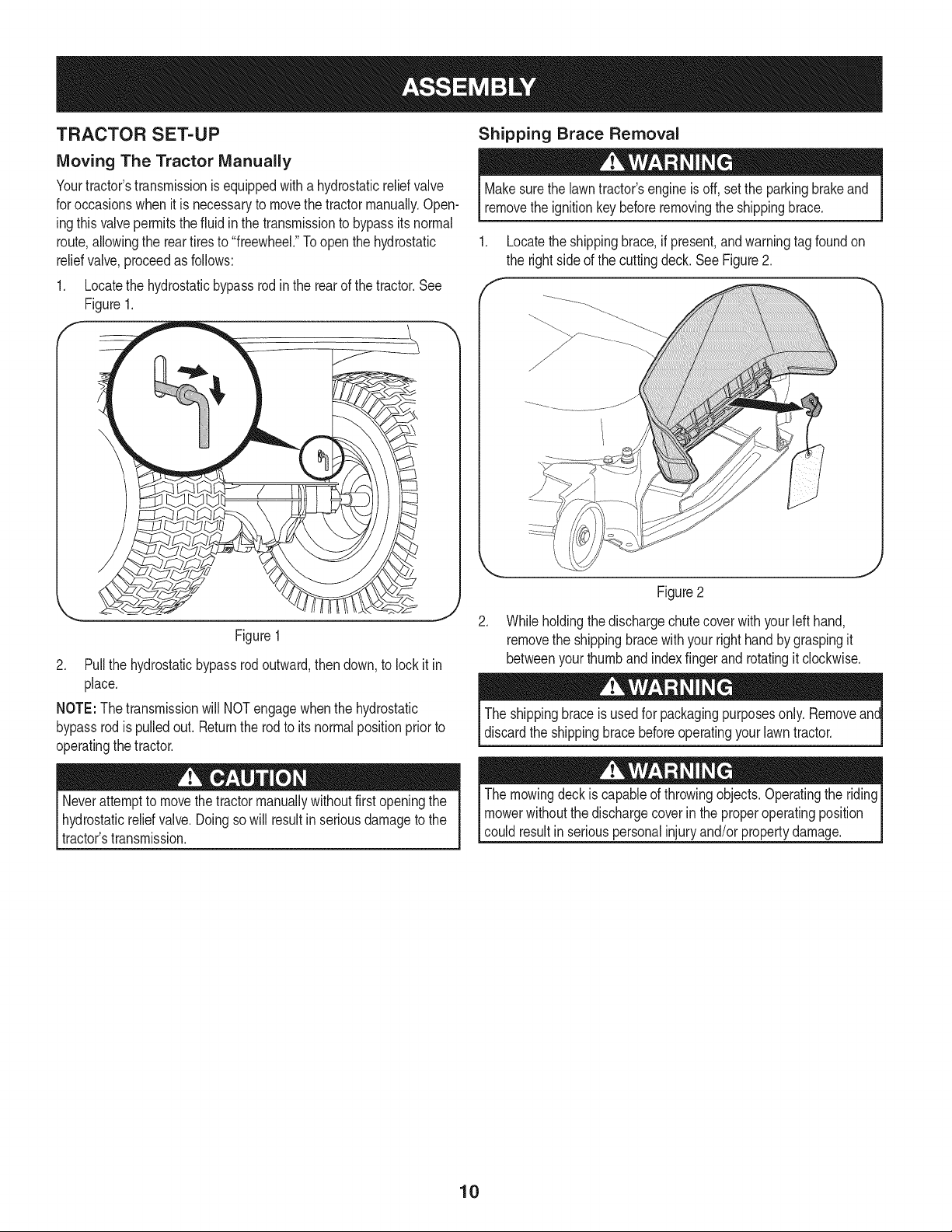
TRACTOR SET-UP
Moving The Tractor Manually
Yourtractor'stransmissionis equippedwitha hydrostaticreliefvalve
for occasionswhenit is necessaryto movethe tractormanually.Open-
ingthis valvepermitsthe fluidin the transmissionto bypassits normal
route,allowingthe reartiresto "freewheel."Toopen the hydrostatic
reliefvalve,proceedas follows:
1. Locatethe hydrostaticbypassrodin the rear of thetractor.See
Figure1.
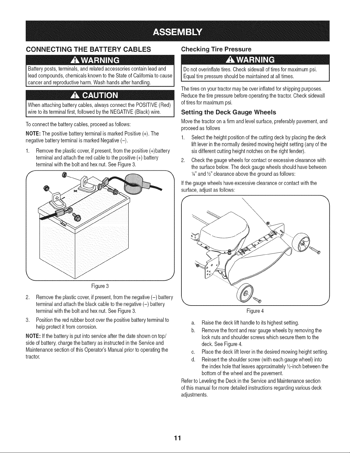
Shipping Brace Removal
Makesurethe lawntractor'sengineisoff, set the parkingbrakeand
removethe ignitionkeybeforeremovingthe shippingbrace.
1. Locatethe shippingbrace, if present,andwarningtag foundon
the rightside of the cuttingdeck.SeeFigure2.
Figure1
2. Pull the hydrostaticbypassrod outward,then down,to lock it in
place.
NOTE:The transmissionwill NOTengagewhenthe hydrostatic
bypassrodis pulledout. Returnthe rodto its normalpositionpriorto
operatingthe tractor.
.
Figure2
Whileholdingthe dischargechutecoverwith yourleft hand,
removethe shippingbracewithyourright handby graspingit
betweenyourthumband indexfingerand rotatingit clockwise.
The shippingbraceis usedfor packagingpurposesonly. Removeant
discardthe shippingbracebeforeoperatingyour lawntractor.
Neverattemptto movethetractormanuallywithoutfirst openingthe
hydrostaticreliefvalve.Doingsowill result inseriousdamageto the
tractor'stransmission.
The mowingdeckis capableof throwingobjects.Operatingthe riding
mowerwithoutthe dischargecoverin theproperoperatingposition
could resultin seriouspersonalinjuryand/orpropertydamage.
10
CONNECTING THE BATTERY CABLES Checking Tire Pressure
Batteryposts,terminals,and relatedaccessoriescontainleadand
leadcompounds,chemicalsknownto the Stateof Californiato cause
cancerand reproductiveharm.Washhandsafterhandling.
Whenattachingbatterycables,alwaysconnectthe POSiTiVE(Red)
wire to its terminalfirst, followedbythe NEGATIVE(Black)wire.
Toconnectthe batterycables,proceedas follows:
NOTE:The positivebatteryterminalis markedPositive(+).The
negativebatteryterminalis markedNegative(-).
1. Removetheplasticcover,if present,fromthe positive(+)battery
terminaland attachthe redcable to the positive(+)battery
terminalwith the bolt andhex nut.See Figure3.
Figure3
2. Removetheplasticcover,if present,fromthe negative(-) battery
terminaland attachthe black cableto the negative(-) battery
terminalwith the bolt andhex nut.See Figure3.
3. Positionthe redrubberbootoverthe positivebatteryterminalto
helpprotectit fromcorrosion.
NOTE: Ifthe batteryis put intoserviceafterthe dateshownontop/
sided battery,chargethe batteryas instructedinthe Serviceand
Maintenancesectionof this Operator'sManualpriorto operatingthe
tractor.
Donot overinflatetires.Checksidewallof tires for maximumpsi.
Equaltire pressureshouldbe maintainedat all times.
The tiresonyourtractormay beoverinflatedfor shippingpurposes.
Reducethe tire pressurebeforeoperatingthe tractor.Checksidewall
of tiresfor maximumpsi.
Setting the Deck Gauge Wheels
Movethe tractoron afirm and levelsurface,preferablypavement,and
proceedas follows
1. Selectthe heightpositionof the cuttingdeck by placingthe deck
liftleverin the normallydesiredmowingheightsetting(anyof the
sixdifferentcuttingheightnotchesonthe rightfender).
2. Checkthe gaugewheelsfor contactor excessiveclearancewith
the surfacebelow.The deck gaugewheelsshouldhavebetween
1A"and 1/2"clearanceabovethe groundas follows:
Ifthe gaugewheelshaveexcessiveclearanceor contactwiththe
surface,adjustas follows:
f
Figure4
a. Raisethe decklift handleto its highestsetting.
b. Removethe frontand reargaugewheelsby removingthe
locknutsand shoulderscrewswhichsecurethemto the
deck. SeeFigure4.
c. Placethe decklift leverin the desiredmowingheightsetting.
d. Reinsertthe shoulderscrew(witheachgaugewheel)into
the indexholethatleavesapproximately_/2-inchbetweenthe
bottomof the wheeland the pavement.
Referto Levelingthe Deckin the Serviceand Maintenancesection
of this manualfor moredetailedinstructionsregardingvariousdeck
adjustments.
11
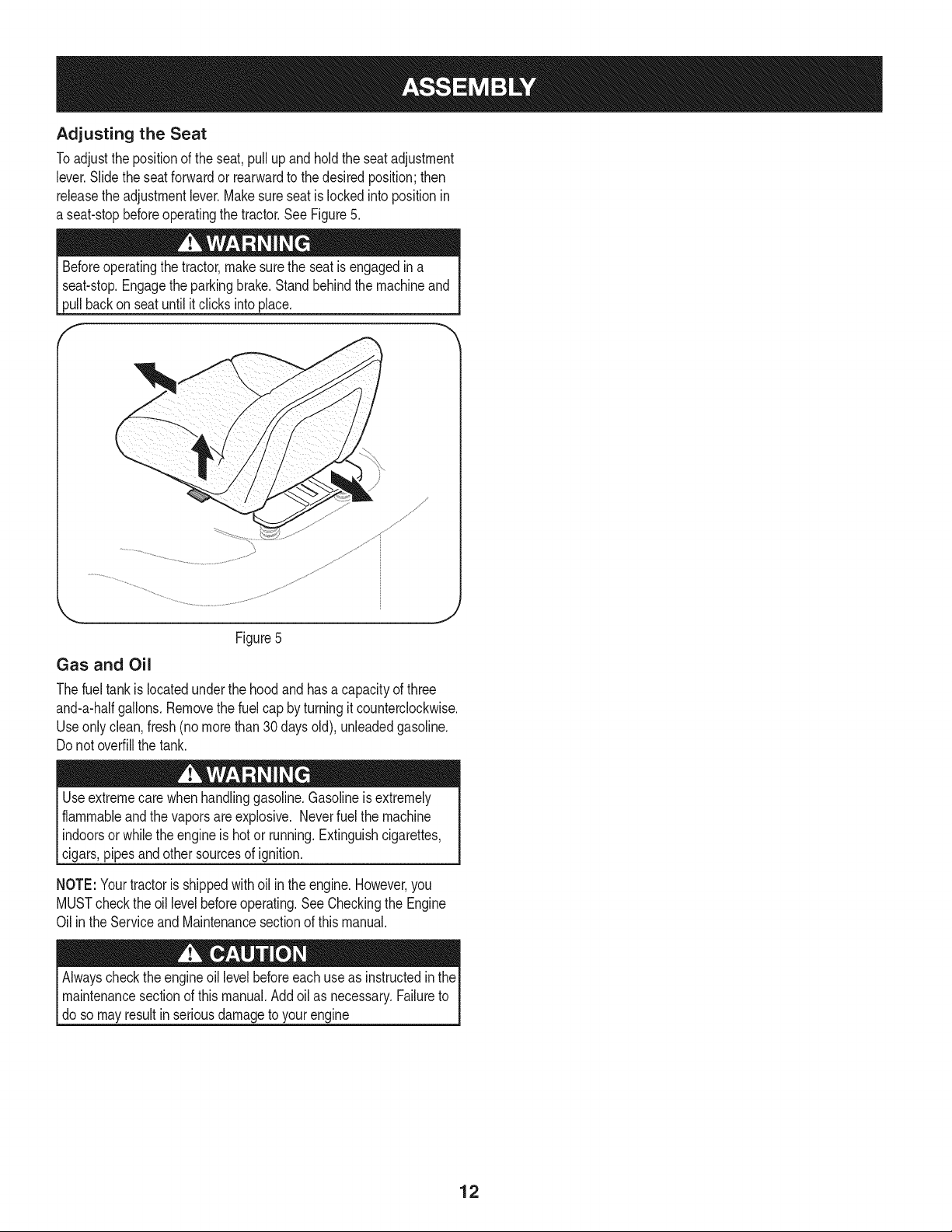
Adjusting the Seat
Toadjustthe positionof the seat,pullup and holdthe seatadjustment
lever.Slidethe seatforwardor rearwardto the desiredposition;then
releasethe adjustmentlever.Makesureseatislockedintopositionin
a seat-stopbeforeoperatingthe tractor.See Figure5.
Beforeoperatingthe tractor,make surethe seatisengagedin a
seat-stop.Engagethe parkingbrake.Standbehindthe machineand
pullbackon seat untilitclicksintoplace.
Gas and Oil
Figure5
J
Thefuel tankis locatedunderthe hood andhasa capacityof three
and-a-halfgallons.Removethe fuelcap by turningit counterclockwise.
Useonlyclean,fresh (no morethan 30daysold), unleadedgasoline.
Do notoverfillthe tank.
Useextremecarewhenhandlinggasoline.Gasolineis extremely
flammableandthe vaporsareexplosive. Neverfuel the machine
indoorsor whilethe engineis hot or running.Extinguishcigarettes,
cigars,pipes andother sourcesof ignition.
NOTE:Yourtractoris shippedwithoil in theengine.However,you
MUSTcheckthe oil levelbeforeoperating.See Checkingthe Engine
Oilin the ServiceandMaintenancesectionof this manual.
Alwayschecktheengineoil levelbeforeeachuseas instructedin the
maintenancesectionof this manual.Addoil as necessary.Failureto
doso mayresultin seriousdamageto yourengine
12
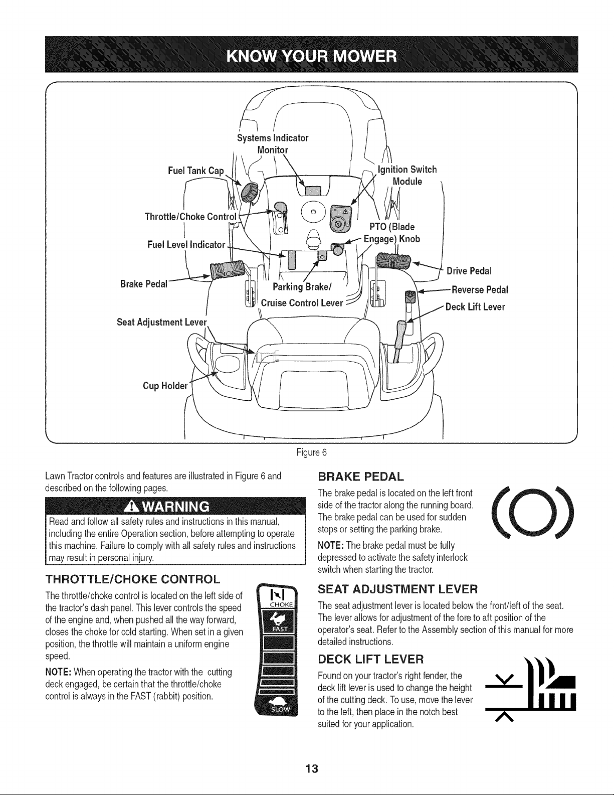
f
FuelTank Cap
Throttle/ChokeControl_
I
Fuel LevelIndicator
Systems Indicator
Monitor
Ignition Switch
Module
PTO(Blade
Knob
Brake Pedal
Seat AdjustmentLever
Parking Brake/
Cruise Control Lever
DrivePedal
Pedal
Lift Lever
Cup Holder"
\
Figure6
LawnTractorcontrolsandfeaturesare illustratedinFigure6 and
describedon thefollowingpages.
Readandfollowall safetyrulesand instructionsinthis manual,
includingtheentireOperationsection,beforeattemptingto operate
this machine.Failureto complywithall safety rulesand instructions
mayresultin personalinjury.
THROTTLE/CHOKE CONTROL
Thethrottle/chokecontrolis locatedon the left sideof
the tractor'sdashpanel.Thislevercontrolsthe speed
of the engineand,whenpushedall the wayforward,
closesthechokefor cold starting.Whenset in agiven
position,the throttlewillmaintaina uniformengine
speed.
NOTE:Whenoperatingthe tractorwiththe cutting
deckengaged,becertainthatthe throttle/choke
controlis alwaysinthe FAST(rabbit)position.
BRAKE PEDAL
The brakepedalis locatedon the leftfront
sideof the tractoralong the runningboard.
The brakepedalcan be usedfor sudden
stopsor settingthe parkingbrake.
NOTE:Thebrakepedalmustbe fully
depressedto activatethe safetyinterlock
switchwhenstartingthe tractor.
SEAT ADJUSTMENT LEVER
The seatadjustmentleveris locatedbelowthe front!leftof the seat.
The leverallowsfor adjustmentof the foreto aft positionof the
operator'sseat. Referto the Assemblysectionof this manualfor more
detailedinstructions.
DECK LiFT LEVER
Foundonyour tractor'srightfender,the V
decklift leveris usedto changethe height
of the cuttingdeck.To use,movethe lever
to the left, thenplace in the notchbest A
suitedforyour application.
13
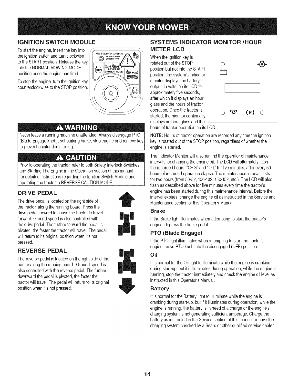
iGNiTiON SWITCH MODULE
Tostart theengine,insertthe key into
the ignitionswitchand turnclockwise
to the STARTposition.Releasethe key
intothe NORMALMOWINGMODE
positiononcethe enginehas fired.
Tostoptheengine,turnthe ignitionkey
counterclockwiseto the STOPposition.
REVERSE PUSH
SUTTON
(BladeEngageknob),set parkingbrake,stopengineand remove
to preventunintendedstarting.
Priorto operatingthe tractor,referto bothSafetyInterlockSwitches
andStartingThe Enginein the Operationsectionof thismanual
fordetailedinstructionsregardingthe IgnitionSwitchModuleand
[operatng the tractor n REVERSECAUTON MODE.
DRIVE PEDAL
Thedrivepedalis locatedon the rightsideof
thetractor,alongthe runningboard.Pressthe
drivepedalforwardto causethe tractorto travel
forward.Groundspeedisalsocontrolledwith
thedrive pedal.Thefurtherforwardthe pedal is
pivoted,the fasterthe tractorwilltravel.The pedal
will returnto itsoriginalpositionwhenit'snot
pressed.
REVERSE PEDAL
The reversepedalislocatedon the right sideof the
tractoralongthe runningboard. Groundspeedis
alsocontrolledwith the reversepedal.Thefurther
downwardthe pedalis pivoted,the fasterthe
tractorwill travel.Thepedalwill returnto itsoriginal
positionwhenit'snot pressed.
|
SYSTEMS INDICATOR MONITOR/HOUR
METER LCD
Whenthe ignitionkeyis
rotatedout of the STOP
positionbut not intothe START
position,thesystem'sindicator
monitordisplaysthe battery's
output,involts,on itsLCDfor
approximatelyfiveseconds,
afterwhich itdisplaysan hour
glassand the hoursof tractor
operation.Oncethe tractoris
started,the monitorcontinually
displaysan hourglassand the
0
I
o (P) o
hoursof tractoroperationon itsLCD.
NOTE: Hoursof tractoroperationare recordedanytimethe ignition
keyis rotatedout of the STOPposition,regardlessof whetherthe
engineis started.
The IndicatorMonitorwillalso remindthe operatorof maintenance
intervalsfor changingthe engineoil. The LCDwill alternatelyflash
the recordedhours,"CHG"and "OIL."for five minutes,after every50
hoursof recordedoperationelapse.The maintenanceintervallasts
for two hours(from50-52, 100-102,150-152,etc.). The LCDwill also
flashas describedabovefor fiveminuteseverytimethe tractor's
enginehasbeen startedduringthis maintenanceinterval.Beforethe
intervalexpires,changethe engineoil as instructedinthe Serviceand
Maintenancesectionof thisOperator'sManual.
Brake
if the Brakelightilluminateswhenattemptingto start the tractor's
engine,depressthe brakepedal.
PTO (Blade Engage)
Ifthe PTOlight illuminateswhenattemptingto startthe tractor's
engine,movePTOknobinto thedisengaged(OFF)position.
Oil
Itis normalfor the Oil lightto illuminatewhile theengineiscranking
duringstart-up,but ifit illuminatesduringoperation,whilethe engineis
running,stopthe tractorimmediatelyandcheckthe engineoil levelas
instructedinthis Operator'sManual.
Battery
Itis normalfor the Batterylight to illuminatewhilethe engineis
crankingduringstart-up,but ifit illuminatesduringoperation,whilethe
engineis running,the batteryis in needof a chargeorthe engine's
chargingsystemis notgeneratingsufficientamperage.Chargethe
batteryas instructedin the Servicesectionof this manualor havethe
chargingsystemcheckedby aSearsor otherqualifiedservicedealer.
14
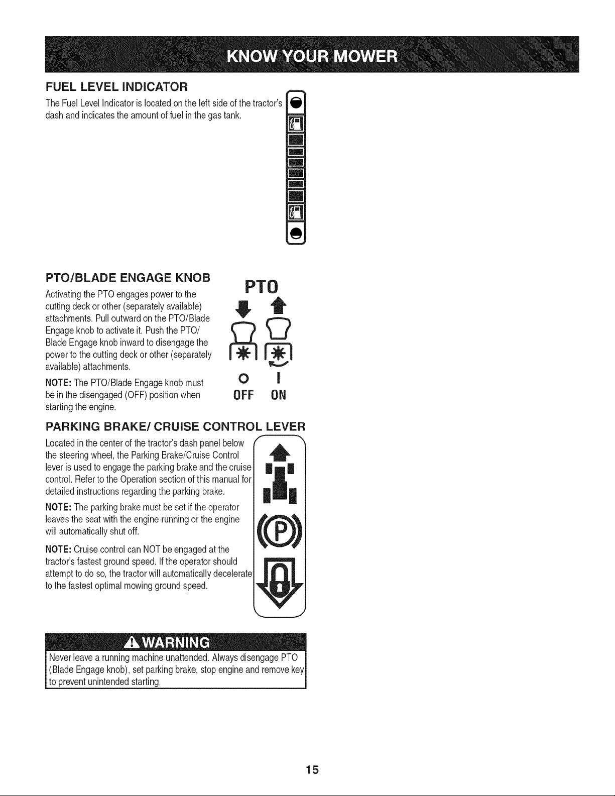
FUEL LEVEL INDICATOR
The FuelLevelIndicatoris locatedon the leftsideof thetractor's
dashandindicatesthe amountof fuel in the gastank.
PTO/BLADE ENGAGE KNOB
Activatingthe PTOengagespowerto the
cuttingdeckor other(separatelyavailable)
attachments.Pulloutwardon the PTO/Blade
Engageknobto activateit. Pushthe PTO/
BladeEngageknobinwardto disengagethe
powerto the cuttingdeck orother (separately
available)attachments.
NOTE:The PTO/BladeEngageknobmust
bein the disengaged(OFF)positionwhen
startingthe engine.
PTO
OFF 0N
PARKING BRAKE/CRUISE CONTROL LEVER
Locatedinthe centerof the tractor'sdash panelbelow
the steeringwheel,the ParkingBrake/CruiseControl
leveris usedto engagethe parkingbrakeandthe cruise
control.Referto the Operationsectionof thismanualfor
detailedinstructionsregardingthe parkingbrake.
NOTE:The parkingbrakemustbe setif the operator
leavesthe seatwiththe enginerunningor the engine _,#_,
will automaticallyshut off.
,krPJ
NOTE:Cruisecontrolcan NOTbeengagedat the
tractor'sfastestgroundspeed.If the operatorshould
attemptto do so,the tractorwill automaticallydecelerate
to the fastestoptimalmowinggroundspeed.
Neverleavea runningmachineunattended.AlwaysdisengagePTO
(BladeEngageknob),setparkingbrake,stopengineandremovekey
to preventunintendedstarting.
15
SAFETY iNTERLOCK SWITCH ES
Thistractoris equippedwitha safetyinterlocksystemfor the protection
of the operator.If the interlocksystemshouldevermalfunction,do not
operatethe tractor.Contacta Searsorotherqualifiedservicedealer.
• The safetyinterlocksystempreventstheenginefromcrankingor
startingunlessthe parkingbrakeis engaged,andthe PTO(Blade
Engage)knobis in thedisengaged(OFF)position.
Theenginewill automaticallyshut offif theoperatorleavesthe
seatbeforeengagingthe parkingbrake.
• TheelectricPTO(BladeEngage)clutchwill automaticallyshut
off if the operatorleavesthe tractor'sseatwiththe PTO(Blade
Engage)knobinthe engaged(ON) position,regardlessof
whetherthe parkingbrakeisengaged.
• Withthe ignitionkeyinthe NORMALMOWINGposition,the
electricPTO(BladeEngage)clutchwillautomaticallyshutoff if
the PTO(BladeEngage)knobis movedintothe engaged(ON)
positionwiththedrive pedalinpositionfor reversetravel.
Do notoperatethe tractorif the interlocksystemis malfunctioning.
Thissystemwasdesignedfor your safetyandprotection.
Startingthe Engine
NOTE: Referto theAssembly& Set-Upsectionof thismanualfor
GasolineandOil fill-up instructions.
1. Insertthe tractorkeyintothe ignitionswitchmodule.
2. Placethe PTO(BladeEngage)knobinthe disengaged(OFF)
position.
3. Engagethe tractor'sparkingbrake.
4. Activatethe chokecontrol by movingthe throttle/chokecontrolall
thewayforwardintothechoke position.
5. Turnthe ignitionkey clockwiseto the STARTposition.After
theenginestarts,releasethe key.It will returnto the NORMAL
MOWINGposition.
Do NOTholdthe keyinthe STARTpositionfor longerthan ten
secondsat a time.Doingso maycause damageto yourengine's
electricstarter.
6. Afterthe enginestarts,deactivatethe chokecontrol.
NOTE: Do NOTleavethe chokecontrolon whileoperatingthetractor.
Doingso will resultina "rich" fuel mixtureandcausethe engineto run
poorly.
STOPPING THE ENGINE
Ifyou strikea foreignobject,stopthe engineanddisconnectthe
sparkplugwire(s). Thoroughlyinspectthe machinefor anydamage.
Repairthedamagebeforerestartingandoperating.
1. If the bladesare engaged,placethe PTO/BladeEngageknobin
the disengaged(OFF) position.
2. Placethe throttlecontrolnear the SLOWposition.
3. Turnthe ignitionkeycounterclockwiseto the STOPposition.
4. Removethe keyfromthe ignitionswitchto preventunintended
starting.
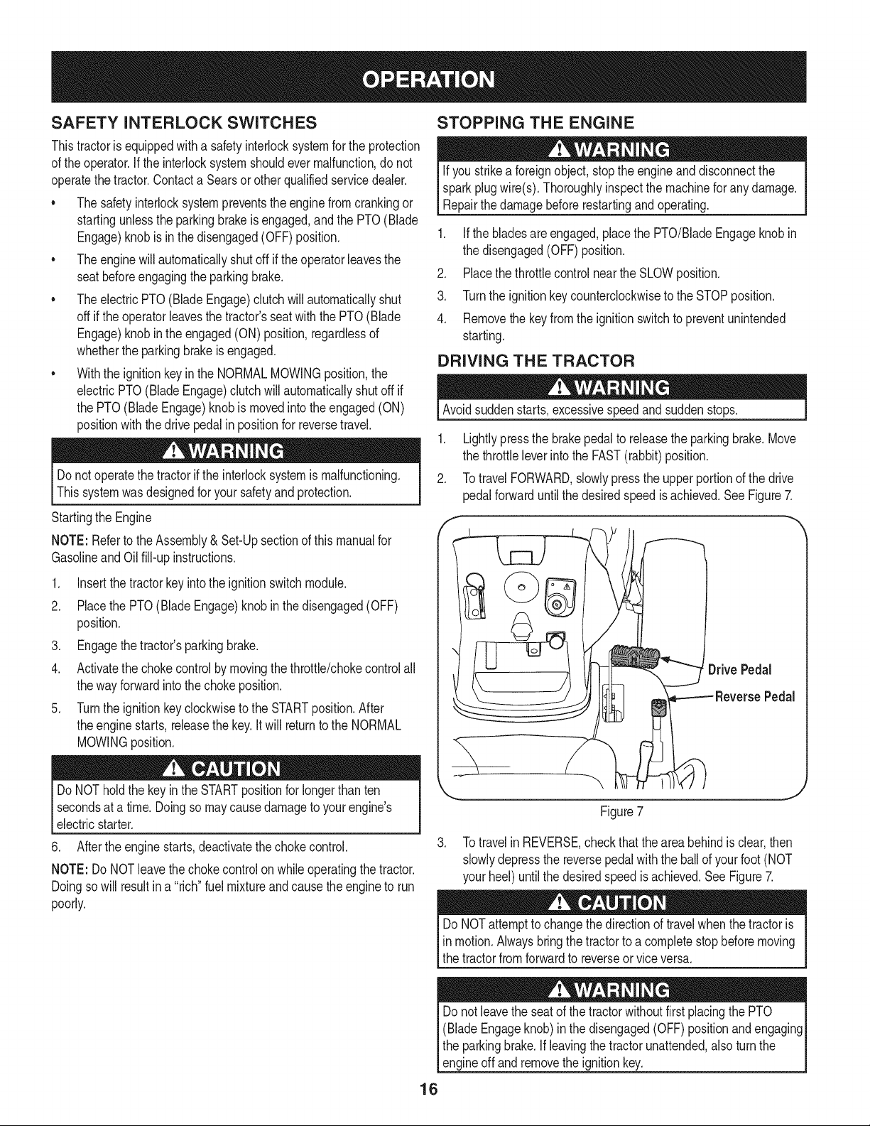
DRIVING THE TRACTOR
Avoidsuddenstarts,excessivespeedand suddenstops.
1. Lightlypressthe brakepedalto releasethe parkingbrake.Move
the throttleleverintothe FAST(rabbit)position.
2. Totravel FORWARD,slowlypressthe upperportionof the drive
pedalforwarduntilthe desiredspeedisachieved.SeeFigure7.
f
/ O 'ti 0.,vow.o,
ReversePedal
J
Figure7
3. Totravel in REVERSE,checkthat the areabehindis clear,then
slowlydepressthe reversepedalwith the ballof yourfoot (NOT
your heel)untilthe desiredspeedis achieved.SeeFigure7.
DoNOTattemptto changethe directionof travel whenthetractoris
in motion.Alwaysbringthe tractorto a completestopbeforemoving
the tractorfromforwardto reverseorvice versa.
Donot leavethe seat of the tractorwithoutfirst placingthe PTO
(BladeEngageknob)in the disengaged(OFF) positionandengaging
the parkingbrake.If leavingthe tractorunattended,alsoturn the
engineoff andremovethe ignitionkey.
16
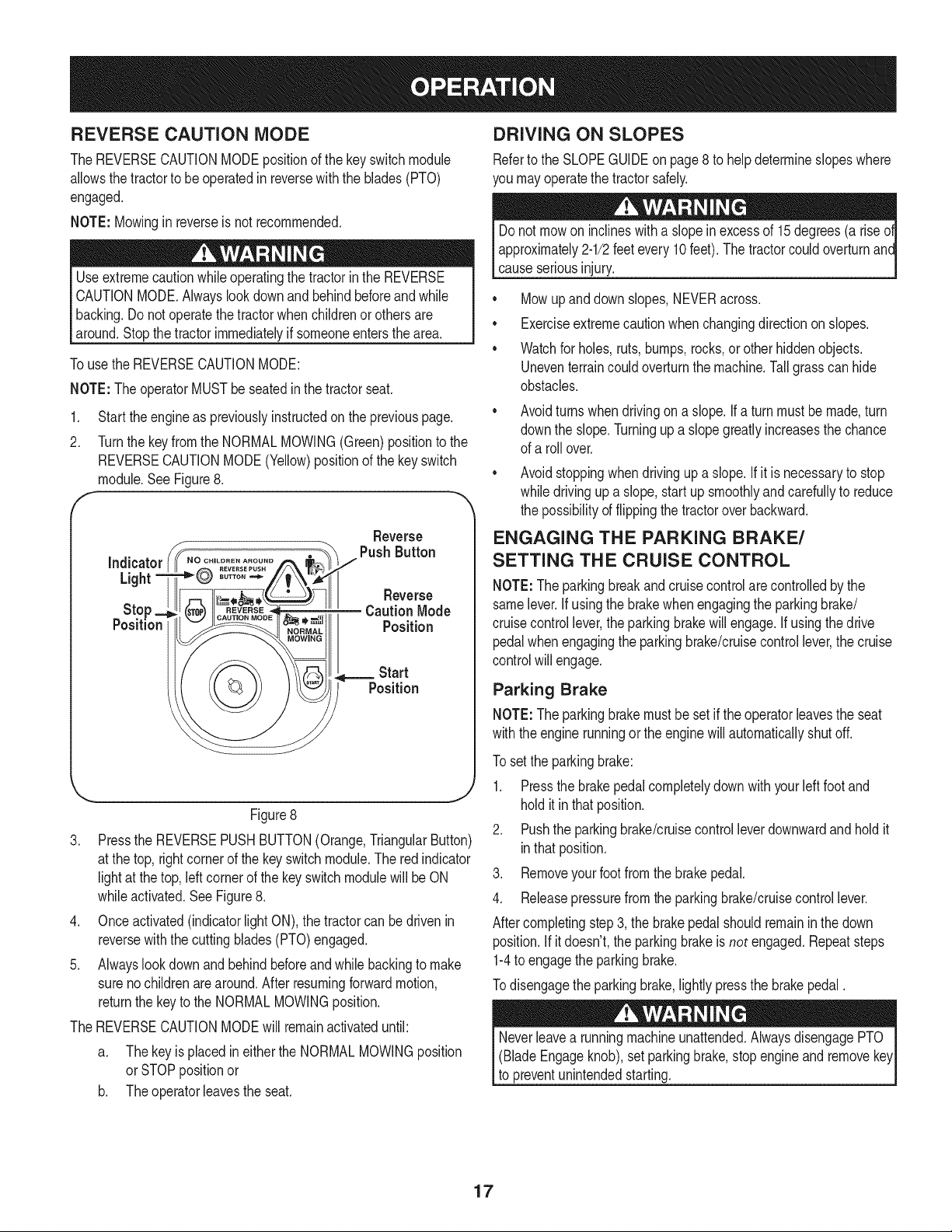
REVERSE CAUTION MODE
The REVERSECAUTIONMODEpositionof thekeyswitch module
allowsthe tractorto beoperatedin reversewiththe blades(PTO)
engaged.
NOTE: Mowinginreverseis not recommended.
Useextremecautionwhile operatingthe tractorin the REVERSE
CAUTIONMODE.Alwayslookdownand behindbeforeandwhile
backing.Do notoperatethe tractorwhenchildrenor othersare
around.Stopthe tractorimmediatelyif someoneentersthearea.
Touse the REVERSECAUTIONMODE:
NOTE:The operatorMUSTbe seatedinthe tractorseat.
1. Start theengineas previouslyinstructedon the previouspage.
2. Turnthe key fromthe NORMALMOWING(Green)positionto the
REVERSECAUTIONMODE(Yellow)positionof the keyswitch
module.SeeFigure8.
F "
Reverse
Figure8
3. Pressthe REVERSEPUSHBUTTON(Orange,TriangularButton)
at the top, rightcornerof the keyswitchmodule.The red indicator
lightat the top, leftcornerof the key switchmodulewillbe ON
whileactivated.SeeFigure8.
4. Onceactivated(indicatorlightON),the tractorcan be drivenin
reversewith the cuttingblades(PTO)engaged.
5. Alwayslookdownand behindbeforeandwhilebackingto make
surenochildrenare around.Afterresumingforwardmotion,
returnthe keyto the NORMALMOWINGposition.
The REVERSECAUTIONMODEwill remainactivateduntil:
a. Thekey is placedin eitherthe NORMALMOWINGposition
orSTOPpositionor
b. Theoperatorieavesthe seat.
DRIVING ON SLOPES
Referto the SLOPEGUIDEon page8 to helpdetermineslopeswhere
you mayoperatethe tractorsafely.
Donot mowon inclineswitha slopeinexcessof 15degrees(a rise
approximately2-1/2feetevery10feet).The tractorcouldoverturnanc
causeseriousinjury.
• Mowupanddown slopes,NEVERacross.
• Exerciseextremecautionwhenchangingdirectionon slopes.
• Watchfor holes,ruts,bumps,rocks,or otherhiddenobjects.
Uneventerraincouldoverturnthe machine.Tallgrasscan hide
obstacles.
Avoidturnswhendrivingon a slope.If a turnmustbe made,turn
downthe slope.Turningupa slopegreatly increasesthe chance
of a roll over.
Avoidstoppingwhen drivingup a slope.If itis necessaryto stop
whiledrivingup a slope,start upsmoothlyand carefullyto reduce
the possibilityof flippingthe tractoroverbackward.
ENGAGING THE PARKING BRAKE/
SETTING THE CRUISE CONTROL
NOTE:Theparkingbreakandcruisecontrolare controlledbythe
samelever.Ifusingthe brakewhenengagingthe parkingbrake/
cruisecontrollever,theparkingbrakewillengage.If usingthe drive
pedalwhenengagingthe parkingbrake/cruisecontrollever,the cruise
controlwill engage.
Parking Brake
NOTE:Theparkingbrakemustbeset if theoperatorleavesthe seat
withthe enginerunningor theenginewillautomaticallyshutoff.
To setthe parkingbrake:
1. Pressthe brakepedalcompletelydownwith yourleftfoot and
holditinthat position.
2. Pushthe parkingbrake/cruisecontrolleverdownwardandholdit
inthat position.
3. Removeyourfoot fromthe brakepedal.
4. Releasepressurefromthe parkingbrake/cruisecontrollever.
Aftercompletingstep3, the brakepedal shouldremaininthe down
position.If itdoesn't,the parkingbrakeisnot engaged.Repeatsteps
1-4to engagethe parkingbrake.
Todisengagethe parkingbrake,lightlypressthe brakepedal.
(BladeEngageknob),set parkingbrake,stopengineand remove
to preventunintendedstarting.
17
Cruise Control
Neverengagethe cruisecontrolleverwhiletravelingin reverse.
Tosetthe cruisecontrol:
1. Slowlypressthe drive pedalwithyourrightfootuntil thedesired
speedis achieved.
2. Lightlypressthe parkingbrake/cruisecontrolleverdownwardand
holdit in thatposition.
3. Removeyour footfromthe drive pedal.
4. Releasepressurefromthe parkingbrake/cruisecontrollever.
Aftercompletingstep3, the drivepedalshouldremainin the down
positionandthetractorwill maintainthe sameforwardspeed.If it
doesn't,the cruisecontrolis not engaged.Repeatsteps 1-4to engage
thecruisecontrol.
Todisengagethe cruise control,lightlypressthe drivepedalor the
brakepedal.
NOTE: Cruisecontrolcannotbe setat the tractor'sfastestground
speed.If the operatorshouldattemptto do so,thetractorwill automati-
callydecelerateto thefastestoptimalmowingground speed.
Tochangethe directionof travelfrom forwardto reversewhencruise
controlis engaged,pressthe brakepedal to disengagethe cruise
controlandbring the tractorto a completestop.Thenslowlypressthe
reversepedalwiththe ballof yourfootto travelin reverse.
USING THE DECK LIFT LEVER
To raisethe cuttingdeck,movethe decklift leverto the left,then place
it in the notchbest suitedfor yourapplication.
OPERATING THE HEADLIGHTS
The lampsareONwheneverthe ignitionkeyis rotatedout of the STOP
position.The lampsturnOFFwhenthe ignitionkeyis movedto the
STOPposition.
ENGAGING THE PTO
Engagingthe PTOtransferspowerto thecuttingdeckor other
(separatelyavailable)attachments.Toengagethe PTO:
1. Movethe throttlecontrolleverto the FAST(rabbit)position.
2. Pullthe PTO/BladeEngageknoboutwardinto theengaged(ON)
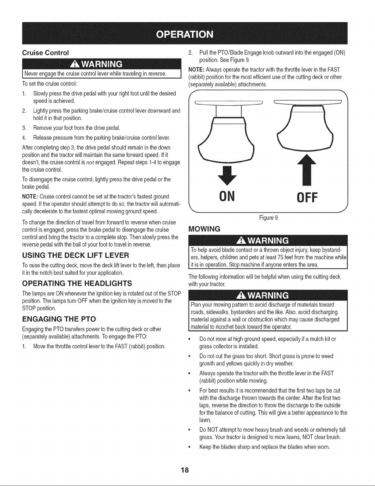
position.SeeFigure9.
NOTE: Alwaysoperatethe tractorwiththe throttleleverin the FAST
(rabbit)positionfor the mostefficientuseof the cuttingdeck or other
(separatelyavailable)attachments.
I _"
!I,
ON
OFF
J
Figure9
MOWING
To helpavoidbladecontactora thrownobjectinjury,keepbystand-
ers,helpers,childrenand petsat least 75feetfromthe machinewhile
it is in operation.Stopmachineif anyoneentersthe area.
The followinginformationwill be helpfulwhenusingthe cuttingdeck
withyourtractor.
Planyourmowingpatternto avoiddischargeof materialstoward
roads,sidewalks,bystandersandthe like.Also,avoiddischarging
materialagainstawall orobstructionwhich maycausedischarged
materialto ricochetbacktowardthe operator.
• Donot mowat highgroundspeed,especiallyif a mulchkitor
grasscollectoris installed.
• Donot cut the grasstooshort. Shortgrassis proneto weed
growthand yellowsquicklyindry weather.
• Alwaysoperatethetractorwiththe throttleleverin the FAST
(rabbit)positionwhilemowing.
• Forbestresultsit is recommendedthatthe first two laps be cut
withthe dischargethrowntowardsthe center.Afterthe firsttwo
laps, reversethedirectionto throwthe dischargeto theoutside
for the balanceof cutting.Thiswill givea betterappearanceto the
lawn.
Do NOTattemptto mowheavybrushand weedsor extremelytall
grass.Yourtractoris designedto mow lawns,NOTclearbrush.
• Keepthe bladessharpandreplacethe bladeswhenworn.
18
Beforeperforminganytypeof maintenance/service,disengageall
controlsandstoptheengine.Waituntilallmovingpartshavecometo
acompletestop.Disconnectsparkplugwireandgroundit againstthe
engineto preventunintendedstarting.Alwayswearsafetyglassesduring
operationorwhileperforminganyadjustmentsor repairs.
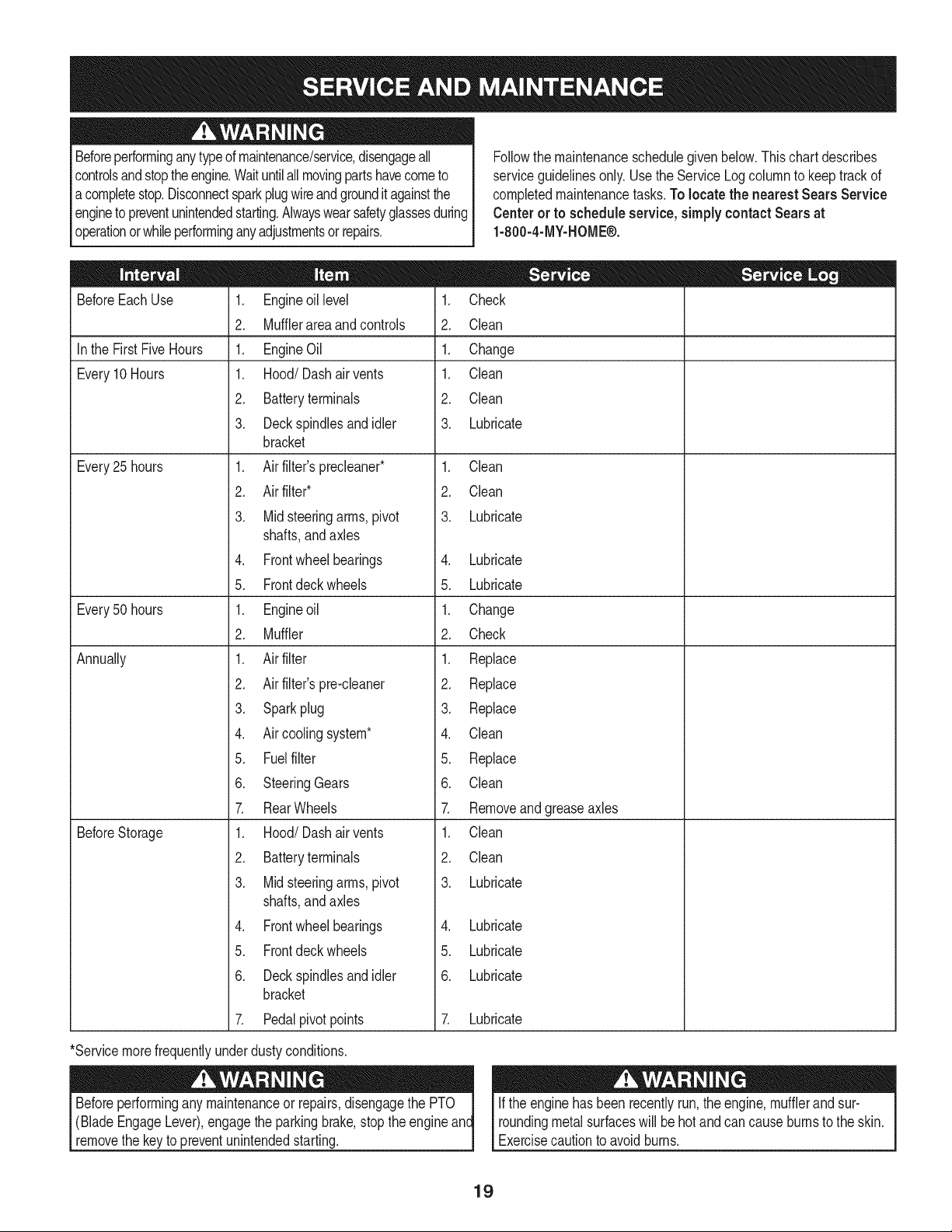
Followthe maintenanceschedulegivenbelow.Thischart describes
serviceguidelinesonly.Usethe Service Logcolumnto keeptrackof
completedmaintenancetasks.To locate the nearest Sears Service
Centeror to scheduleservice,simplycontactSears at
1-800-4-MY-HOME®.
BeforeEachUse
In the First FiveHours
Every10 Hours
Every25 hours
Every50 hours
Annually
BeforeStorage
1. Engineoil level
2. Mufflerarea andcontrols
1. EngineOil
1. Hood/Dash air vents
2. Batteryterminals
3. Deckspindlesand idler
bracket
1. Air filter'sprecleaner*
2. Air filter*
3. Mid steeringarms,pivot
shafts,andaxles
4. Frontwheelbearings
5. Frontdeck wheels
1. Engineoil
2. Muffler
1. Air filter
2. Air filter'spre-cleaner
3. Sparkplug
4. Air coolingsystem*
5. Fuelfilter
6. SteeringGears
7. RearWheels
1. Hood/Dash air vents
2. Batteryterminals
3. Mid steeringarms,pivot
shafts,andaxles
4. Frontwheelbearings
5. Frontdeck wheels
6. Deckspindlesand idler
bracket
7. Pedalpivot points
1. Check
2. Clean
1. Change
1. Clean
2. Clean
3. Lubricate
1. Clean
2. Clean
3. Lubricate
4. Lubricate
5. Lubricate
1. Change
2. Check
1. Replace
2. Replace
3. Replace
4. Clean
5. Replace
6. Clean
7. Removeand greaseaxles
1. Clean
2. Clean
3. Lubricate
4. Lubricate
5. Lubricate
6. Lubricate
7. Lubricate
*Servicemorefrequentlyunderdustyconditions.
(BladeEngageLever),engagethe parkingbrake,stopthe engine
removethe keyto preventunintendedstarting.
If the enginehasbeenrecentlyrun,theengine,mufflerand sur-
roundingmetal surfaceswill behotand can cause burnsto the skin.
Exercisecautionto avoidburns.
19
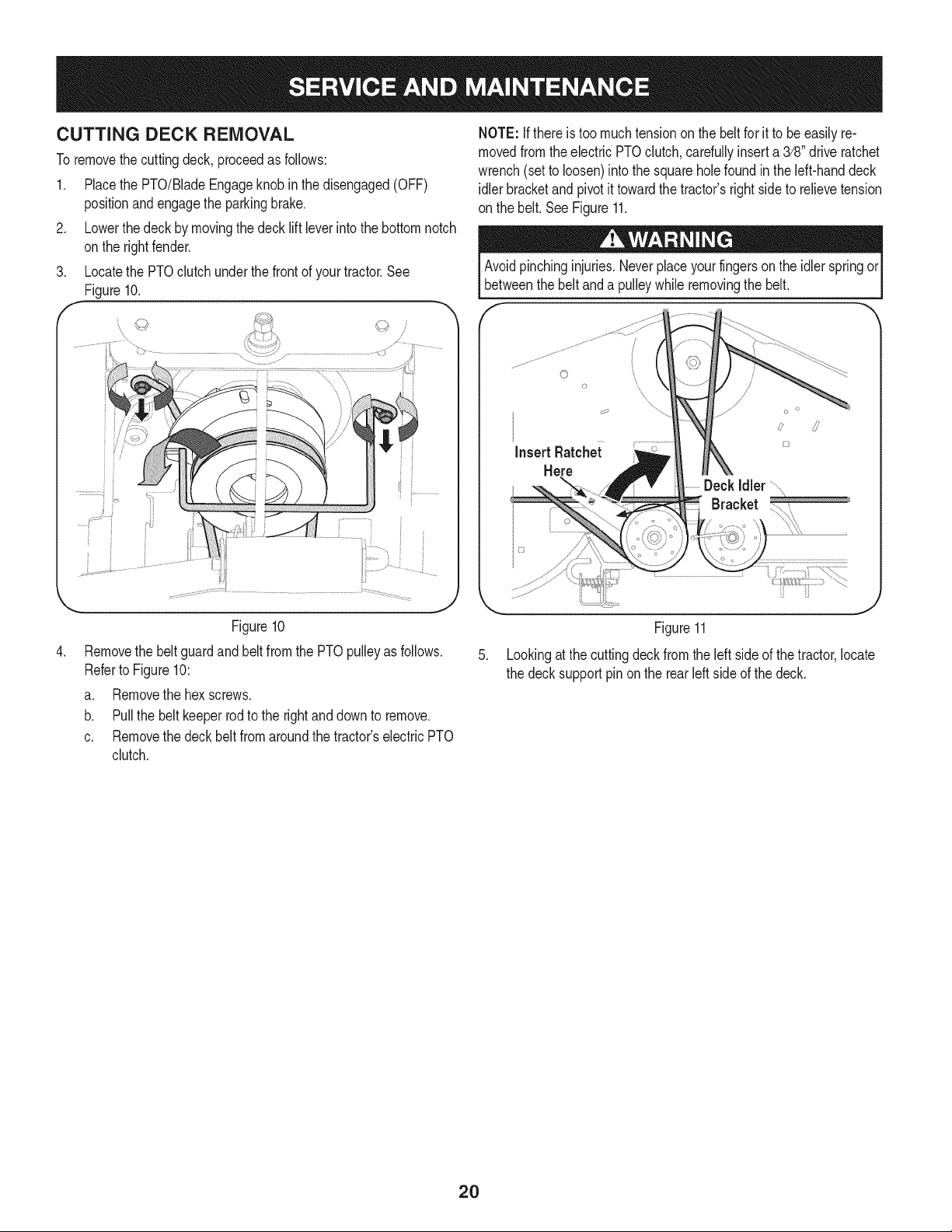
CUTTING DECK REMOVAL
To removethecuttingdeck, proceedas follows:
1. Placethe PTO/BladeEngageknobin the disengaged(OFF)
positionandengagethe parkingbrake.
2. Lowerthe deck by movingthe deck lift leverintothe bottomnotch
onthe rightfender.
Locatethe PTOclutchunderthe frontof yourtractor.See
Figure10.
.
J
Figure10
Removethe beltguardand beltfromthe PTOpulleyas follows.
Referto Figure10:
a. Removethe hexscrews.
b. Pull the beltkeeperrod to the rightand downto remove.
c. Removethe deckbelt fromaroundthe tractor'selectricPTO
clutch.
NOTE: Ifthere is too muchtensionon thebelt for it to be easilyre-
movedfromtheelectric PTOclutch,cardully inserta 3/8" driveratchet
wrench(setto loosen)intothe squareholefoundin the left-handdeck
idlerbracketand pivotit towardthe tractor'srightsideto relievetension
on the belt.SeeFigure11.
Avoidpinchinginjuries.Neverplaceyourfingersonthe idlerspringor
betweenthe beltanda pulleywhileremovingthe belt.
.
InsertRatche;c
Here
_Y
Figure11
Lookingat thecuttingdeckfrom the leftside of thetractor,locate
the decksupportpinon the rear leftsideof thedeck.
2O
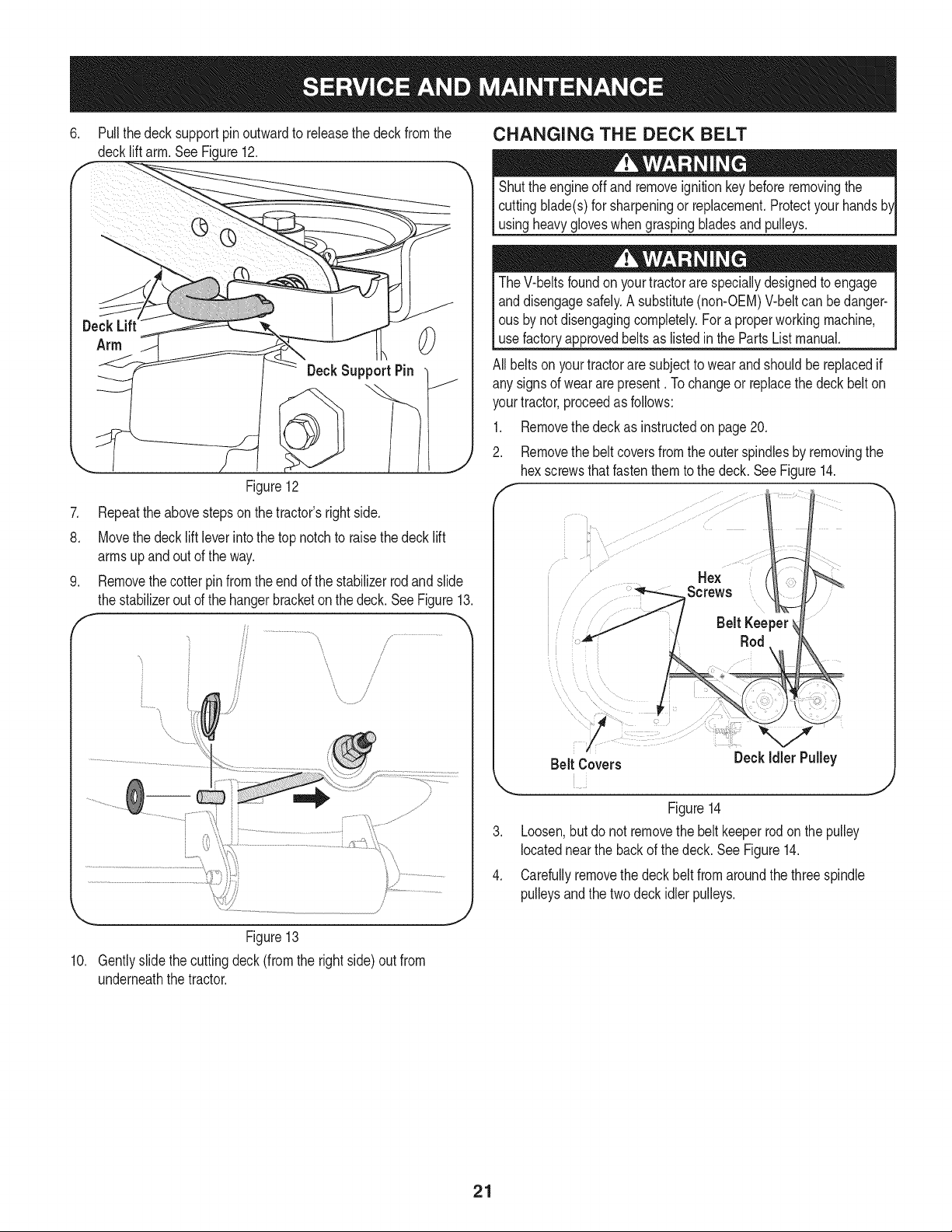
6. Pull thedeck supportpinoutwardto releasethe deck fromthe
decklift arm.See Figure12.
0
DeckSupport Pin
.
8.
Figure12
Repeattheabovestepsonthe tractor'srightside.
Movethe decklift leverintothe topnotchto raisethe deck lift
armsup andout of the way.
Removethe cotterpin fromthe endof the stabilizerrodand slide
the stabilizerout ofthe hangerbracketonthe deck.SeeFigure13.
/?
/
___'
Figure13
10. Gentlyslidethe cuttingdeck(from the rightside)out from
underneaththe tractor.
CHANGING THE DECK BELT
Shutthe engineoff andremoveignitionkeybeforeremovingthe
cuttingblade(s)for sharpeningor replacement.Protectyourhands
usingheavygloveswhengraspingbladesand pulleys.
TheV-beltsfoundon yourtractorare speciallydesignedto engage
anddisengagesafely.A substitute(non-OEM)V-beltcan bedanger-
ous by notdisengagingcompletely.Fora properworkingmachine,
use factoryapprovedbeltsas listedin the PartsListmanual.
All beltson yourtractoraresubjectto wearand shouldbereplacedif
any signsof wear arepresent. Tochangeor replacethe deck belton
yourtractor,proceedas follows:
1. Removethe deckas instructedon page20.
2. Removethe beltcoversfromtheouter spindlesby removingthe
hexscrewsthat fastenthem to the deck.See Figure14.
Hex
Screws
Belt Keeper
Rod
Figure14
3. Loosen,but do not removethe belt keeperrodon the pulley
locatednear the backof thedeck. SeeFigure14.
4. Carefullyremovethe deck belt from aroundthe threespindle
pulleysand the two deckidlerpulleys.
21
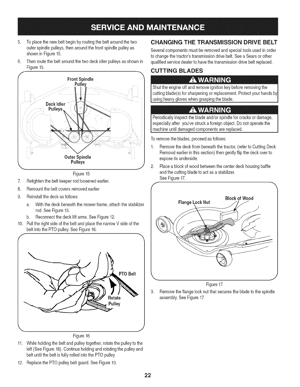
.
Toplacethe newbelt beginby routingthe beltaroundthe two
outerspindlepulleys,then aroundthefront spindlepulleyas
shownin Figure15.
6. Thenroutethe beltaroundthe twodeckidler pulleysas shownin
Figure15.
f
FrontSpindle
" Deck
Pulleys ....
Outer Spindle
Pulleys
Figure15
7. Retightenthe belt keeperrodloosenedearlier.
8. Remountthebelt coversremovedearlier
9. Reinstallthe deckas follows:
a. Withthe deck beneaththe mowerframe,attachthe stabilizer
rod. SeeFigure13.
b. Reconnectthedeck liftarms.SeeFigure12.
10. Pull the rightside ofthe beltand placethe narrowV side of the
belt intothe PTOpulley.See Figure16.
PTO Belt
CHANGING THE TRANSMISSION DRIVE BELT
Severalcomponentsmustbe removedand specialtoolsusedin order
to changethe tractor'stransmissiondrivebelt.See a Searsorother
qualifiedservicedealerto havethe transmissiondrivebelt replaced.
CUTTING BLADES
Shutthe engineoff andremoveignitionkeybeforeremovingthe
cuttingblade(s)for sharpeningor replacement.Protectyourhands
usingheavygloveswhengraspingthe blade.
Periodicallyinspectthe blade and/orspindlefor cracksor damage,
especiallyafter you'vestrucka foreignobject.Do notoperatethe
machineuntildamagedcomponentsare replaced.
To removethe blades,proceedas follows:
1. Removethe deckfrom beneaththe tractor,(referto CuttingDeck
Removalearlierinthis section)then gentlyflip the deckoverto
exposeitsunderside.
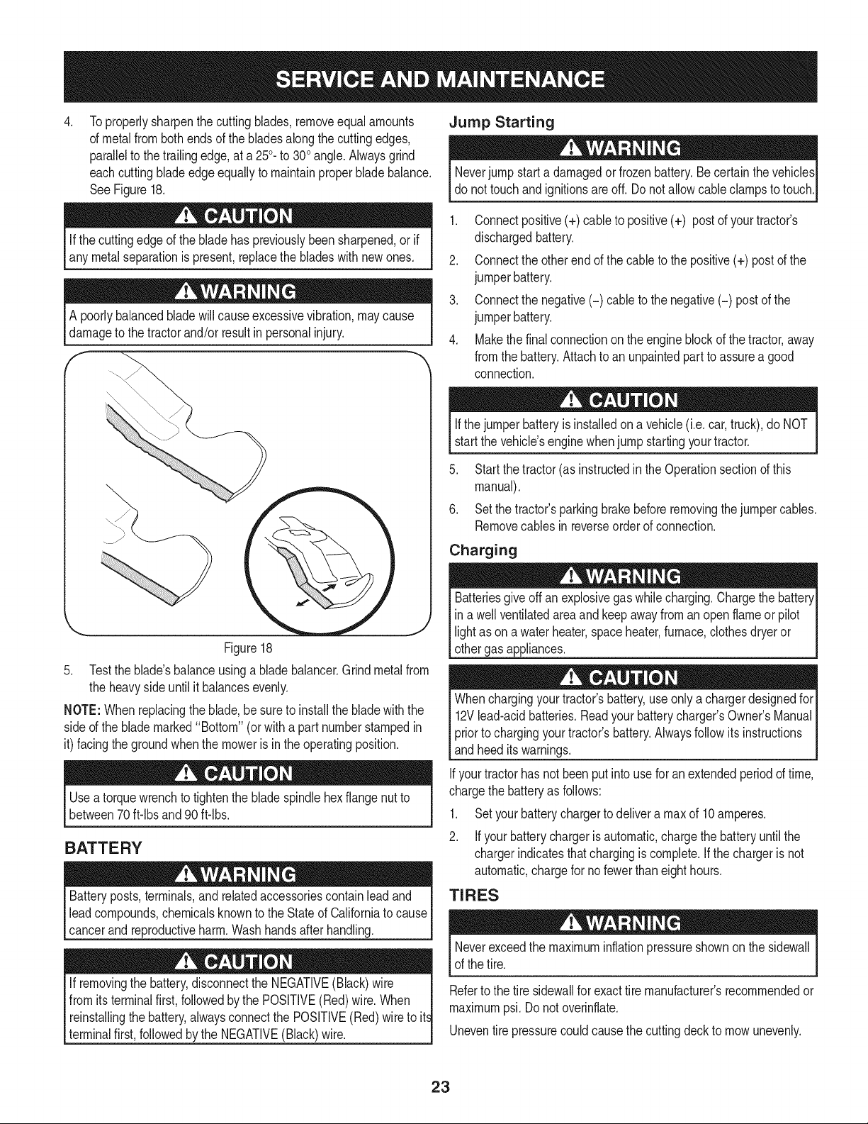
2. Placea blockof woodbetweenthe centerdeckhousingbaffle
andthe cuttingbladeto actas a stabilizer.
See Figure17.
f
FlangeLockNut
Block of Wood
)
Figure17
3. Removethe flangelocknutthat securesthe bladeto the spindle
assembly.SeeFigure17.
J
Figure16
11. Whileholdingthe beltandpulleytogether,rotatethepulleyto the
left(See Figure18).Continueholdingandrotatingthepulleyand
belt untilthe beltis fullyrolledintothe PTOpulley.
12. Replacethe PTOpulleybelt guard.See Figure10.
22
4. Jump Starting
Toproperlysharpenthe cuttingblades,removeequal amounts
of metalfromboth endsof the bladesalongthe cuttingedges,
parallelto thetrailingedge,at a 250.to 300angle.Alwaysgrind
eachcuttingbladeedgeequallyto maintainproper bladebalance.
SeeFigure18.
Neverjump starta damagedor frozenbattery.Becertainthe vehicles
do nottouchand ignitionsareoff. Donot allowcableclampsto touch.
Ifthe cuttingedgeof the bladehas previouslybeensharpened,orif
any metalseparationis present,replacethe bladeswithnewones.
A poorlybalancedbladewillcauseexcessivevibration,maycause
damage to the tractor and/or result in personal injury.
\..\
.2
J
Figure18
5. Testthe blade'sbalanceusinga bladebalancer.Grind metalfrom
the heavyside untilit balancesevenly.
NOTE:Whenreplacingthe blade,besureto installthe bladewiththe
sided the blade marked"Bottom"(orwith a part numberstampedin
it) facingthe groundwhenthe moweris in the operatingposition.
Usea torquewrenchto tightenthe blade spindlehexflange nutto
between70 ft-lbs and 90ft-lbs.
BATTERY
Batteryposts,terminals,and relatedaccessoriescontainleadand
leadcompounds,chemicalsknownto the Stateof Californiato cause
cancerand reproductiveharm.Washhandsafterhandling.
If removingthe battery,disconnectthe NEGATIVE(Black)wire |
from itsterminalfirst, followedby the POSITIVE(Red)wire.When
t
reinstallingthe battery,alwaysconnectthe POSITIVE(Red)wire to it
terminalfirst,followedbythe NEGATIVE(Black)wire.
1. Connectpositive(+) cableto positive(+) post of yourtractor's
dischargedbattery.
2. Connectthe otherendof the cableto thepositive(+) post of the
jumperbattery.
3. Connectthe negative(-) cable to the negative(-) postof the
jumperbattery.
4. Makethefinal connectionon the engineblockof thetractor,away
fromthe battery.Attachto an unpaintedpart to assurea good
connection.
Ifthejumperbatteryis installedona vehicle(i.e. car,truck),do NOT
start the vehicle'senginewhenjump startingyourtractor.
5. Startthe tractor(as instructedin theOperationsectionof this
manual).
6. Setthe tractor'sparkingbrakebeforeremovingthejumpercables.
Removecablesin reverseorderof connection.
Charging
Batteriesgiveoff an explosivegas whilecharging.Chargethe battery[
in a wellventilatedareaandkeepawayfrom an openflameor pilot [
lightas on a waterheater,spaceheater,furnace,clothesdryeror [
othergas appliances. J
Whenchargingyourtractor'sbattery,use onlya chargerdesignedfor
12Vlead-acidbatteries.Readyourbatterycharger'sOwner'sManual
priorto chargingyourtractor'sbattery.Alwaysfollowits instructions
andheed itswarnings.
Ifyourtractorhas notbeenput intouse for an extendedperiodof time,
chargethe batteryas follows:
1. Setyourbatterychargerto delivera max of 10 amperes.
2. If your batterychargeris automatic,chargethe batteryuntilthe
chargerindicatesthatchargingis complete.If thechargeris not
automatic,chargefor no fewerthaneighthours.
TIRES
Neverexceedthe maximuminflationpressureshownon thesidewall
of the tire.
Referto thetire sidewallfor exacttire manufacturer'srecommendedor
maximumpsi. Do notoverinflate.
Uneventire pressurecouldcausethe cuttingdeckto mowunevenly.
23
FUSE
Beforeservicing,repairing,or inspecting,alwaysdisengagePTO
(BladeEngageknob),set parkingbrake,stopengineand remove
to preventunintendedstarting.
Afuse isinstalledinyourtractor'swiringharnessto protectthe trac-
tor'selectricalsystemfrom damagecausedbyexcessiveamperage.
Ifthe electricalsystemdoesnot function,or yourtractor'senginewill
notcrank,first checkto be certainthatthe fuse hasnot blown.It is
locatedunderthe hood,mountedbehindthe top of the dashpanelon
the supportbar.
Alwaysusea replacementfusewith the sameamperagecapacity as
the blownfuse.
MAINTENANCE
Beforeperformingany maintenanceor repairs,disengagePTO
(BladeEngageknOb),set parkingbrake,stopengineand remove
to preventunintendedstarting.
CLEANING THE TRACTOR
Anyfuel oroil spilledonthe machineshouldbewipedoff promptly.Do
NOTallowdebristo accumulatearoundthe coolingfinsof the engine,
thetransmission'scoolingfan or on any otherpartof the machine,
especiallythe beltsandpulleys.
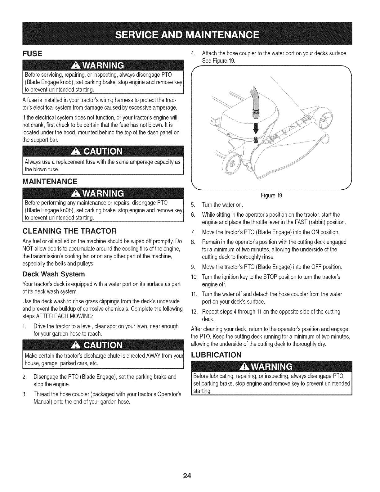
Deck Wash System
Yourtractor'sdeck is equippedwith awater port on itssurfaceas part
of itsdeckwash system.
Usethedeck washto rinsegrassclippingsfrom the deck'sunderside
andpreventthe buildupof corrosivechemicals.Completethe following
stepsAFTEREACHMOWING:
1. Drivethe tractorto a level,clearspotonyour lawn,nearenough
for yourgardenhoseto reach.
Makecertainthe tractor'sdischargechuteisdirectedAWAYfrom youl
house,garage,parkedcars,etc.
2. Disengagethe PTO(Blade Engage),setthe parkingbrakeand
stoptheengine.
3. Threadthe hosecoupler(packagedwith yourtractor'sOperator's
Manual)ontothe endof your gardenhose.
4. Attachthe hosecouplerto thewaterporton yourdeckssurface.
See Figure19.
\\
\\
Figure19
5. Turnthe wateron.
6. Whilesittingin the operator'spositionon the tractor,start the
engineand placethe throttleleverinthe FAST(rabbit)position.
7. Movethetractor'sPTO(BladeEngage)intothe ON position.
8. Remainintheoperator'spositionwith the cuttingdeckengaged
for a minimumof two minutes,allowingthe undersideof the
cuttingdeckto thoroughlyrinse.
9. Movethetractor'sPTO(BladeEngage)intothe OFF position.
10. Turnthe ignitionkeyto the STOPpositionto turn the tractor's
engineoff.
11. Turnthe wateroff anddetach the hosecouplerfromthewater
port on yourdeck'ssurface.
12. Repeatsteps4 through11onthe oppositesideof the cutting
deck.
Aftercleaningyourdeck, returnto the operator'spositionandengage
the PTO.Keepthecuttingdeck runningfor a minimumof two minutes,
allowingthe undersideof the cuttingdeck to thoroughlydry.
LUBRICATION
Beforelubricating,repairing,orinspecting,alwaysdisengagePTO,
setparkingbrake,stopengine andremovekey to preventunintended
starting.
24
Front Wheels
Eachof the front wheelaxlesand rimsis equippedwitha grease
fitting.See Figure20. Lubricatewitha No. 2 multi-purposegrease
appliedwitha greasegunafterevery25 hoursof tractoroperation.
?
J_
\ \
Figure20
Pivot Points & Linkage
Lubricateall the pivotpointson thedrive system,parkingbrakeand lift
linkageat leastoncea seasonwithlightoil.
Deck Wheels
Eachof the tractordeck'sfront gaugewheelsisequippedwitha
greasefitting.Lubricatewitha No. 2 multi-purposegreaseappliedwith
a greasegunafter every25 hoursof tractoroperation.
Deck Spindle
Greasefittingscanbe foundon eachdeckspindle.See Figure21.
Lubricatewith 251HEPgreaseoran equivalentNo.2 multi-purpose
lithiumgrease.Usinga greasegun, applytwostrokes(minimum)or
sufficientgreaseto the spindleshaft.
f \J
Figure21
ADJUSTMENTS
Shutthe engineoff, removethe ignitionkey andengagethe parking
brakebeforemakingadjustments.Protectyourhandsby usingheavy
gloveswhenhandlingthe blades.
NOTE:Checkthe tractor'stire pressurebeforeperformingany deck
levelingadjustments.Referto Tireson page23 for informationregard-
ingtirepressure.
Leveling the Deck (Front To Rear)
The frontof thecuttingdeckis supportedby a stabilizerbarthat can
beadjustedto levelthe deck fromfrontto rear.The frontof thedeck
shouldbe between1/4"and 3/8" lowerthan the rearof the deck.Adjust
if necessaryas follows:
1. Parkthe tractorparkedon a firm, levelsurfaceand placethe deck
liftleverin the middleposition.
2. Rotatethe bladenearestthe dischargechutecover sothat it is
parallelwith the tractor.
3. Measurethedistancefromthe front of the bladetip to the ground
andthe rearof the bladetip tothe ground.Thefirst measurement
takenshouldbe between1/4"and 3/8" lessthanthe second
measurement.
Determinethe approximatedistancenecessaryfor properadjustment
and proceed,ifnecessary.
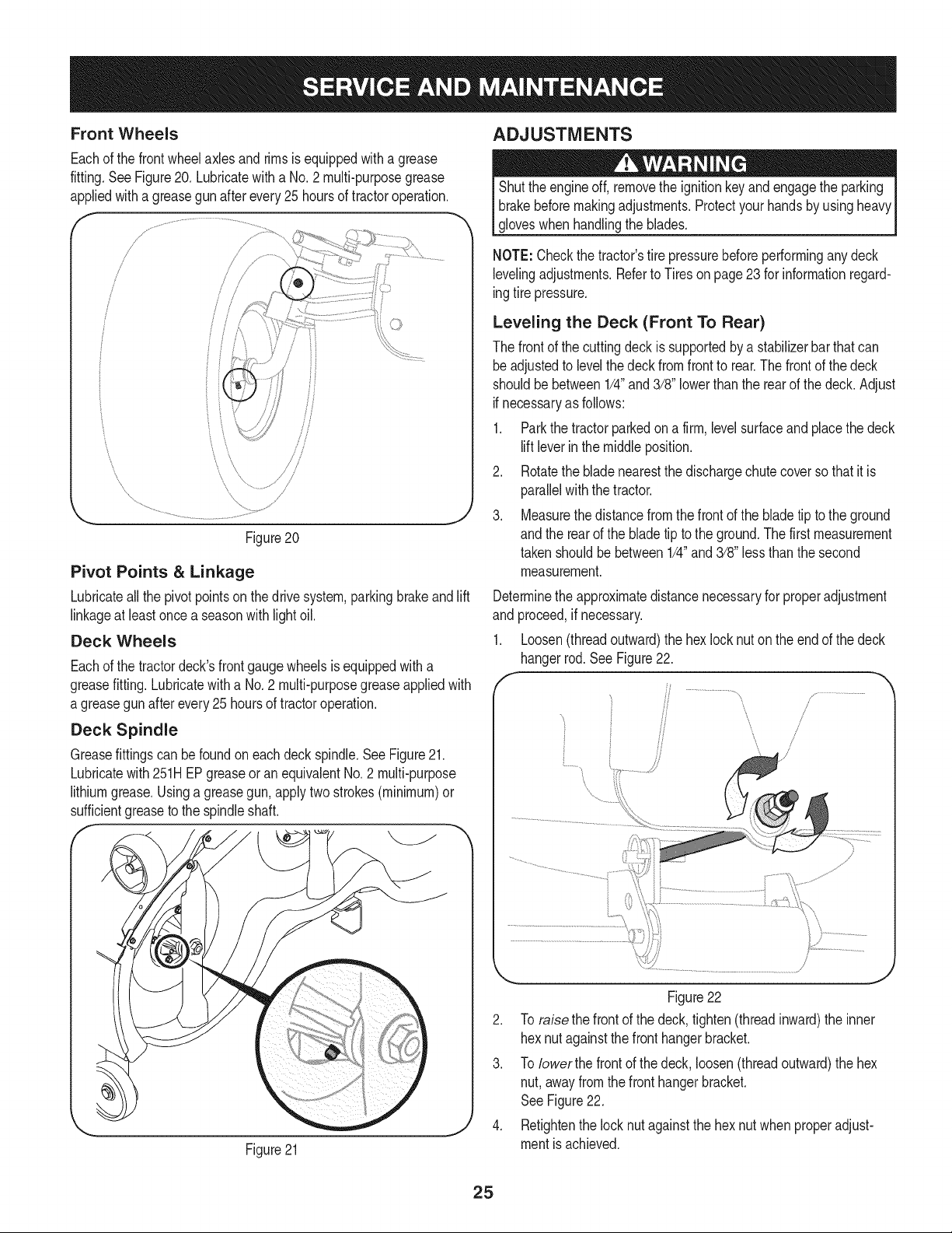
1. Loosen(threadoutward)the hexlock nut on the endof the deck
hangerrod.SeeFigure22.
/
/
!
Figure22
2. To raise the front of the deck,tighten(threadinward)the inner
hexnutagainstthe fronthangerbracket.
3. To Iowerthe frontof the deck,loosen(threadoutward)the hex
nut,awayfromthe fronthangerbracket.
SeeFigure22.
4. Retightenthe locknutagainstthe hex nutwhenproperadjust-
mentis achieved.
25
Leveling the Deck (Side to Side)
Ifthe cuttingdeckappearsto be mowingunevenly,a side to side
adjustmentcan be performed.Adjustif necessaryas follows:
1. Withthe tractorparkedon a firm,levelsurface,placethe decklift
leverinthe middlepositionandrotateboth bladesso thatthey are
perpendicularwiththe tractor.
2. Measurethe distancefrom the outsideof the leftblade tip to the
groundandthe distancefromtheoutsideof the rightbladetip to
theground.Bothmeasurementstakenshouldbeequal. If they're
not,proceedto the nextstep.
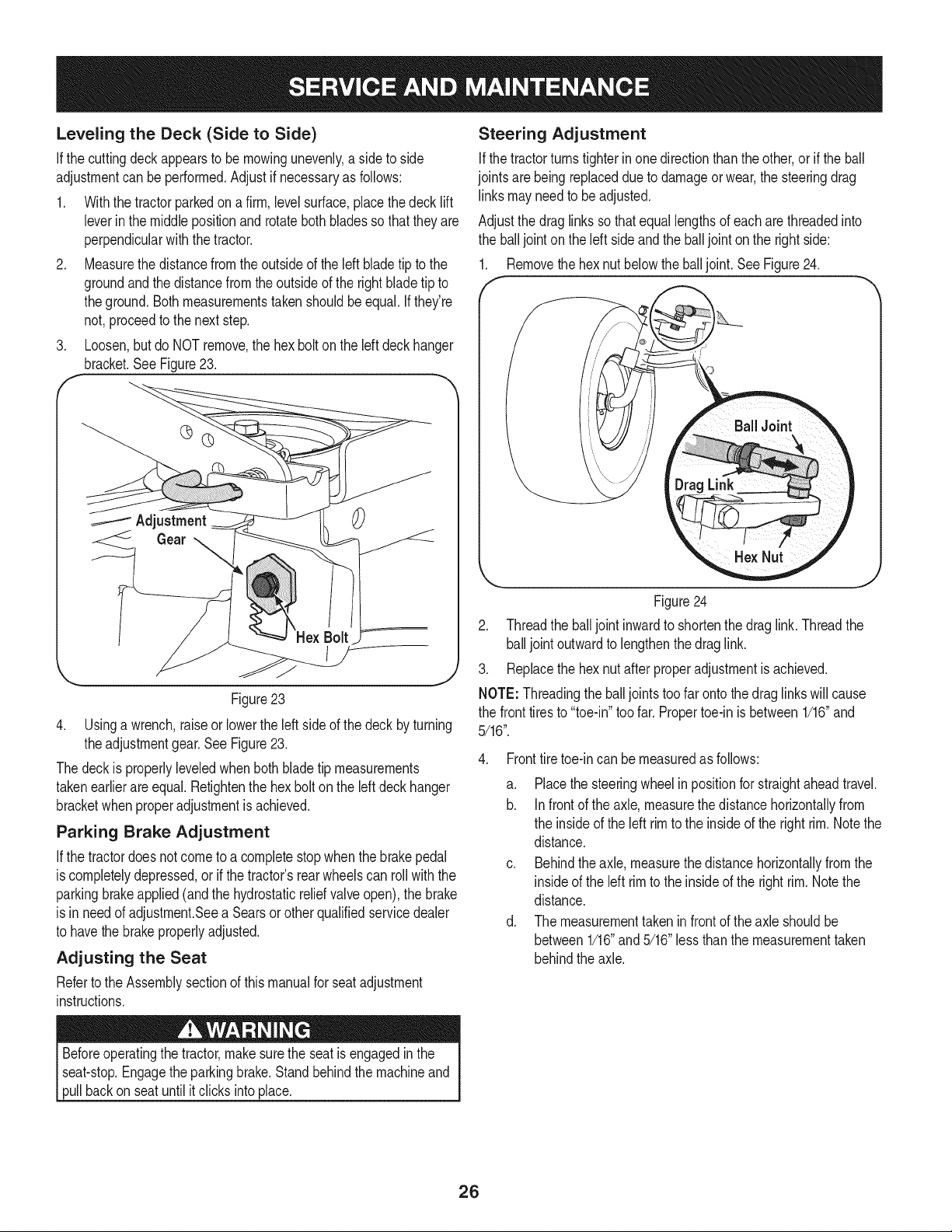
3. Loosen,butdo NOT remove,the hexbolt onthe left deckhanger
bracket.See Figure23.
Adjustment
Figure23
4. Usinga wrench,raiseor lowerthe left sideof thedeck byturning
theadjustmentgear.See Figure23.
Thedeckis properlyleveledwhenbothbladetip measurements
takenearlierareequal. Retightenthe hexbolton the left deckhanger
bracketwhenproperadjustmentis achieved.
Parking Brake Adjustment
Ifthe tractordoesnot cometo a completestopwhenthe brakepedal
iscompletelydepressed,or ifthe tractor'srearwheelscan roll withthe
parkingbrakeapplied(andthe hydrostaticreliefvalveopen),the brake
is in needof adjustment.Seea Searsorother qualifiedservicedealer
to havethe brakeproperlyadjusted.
Adjusting the Seat
Referto the Assemblysectionof this manualfor seat adjustment
instructions.
Steering Adjustment
Ifthe tractorturnstighterinone directionthanthe other,or ifthe ball
jointsarebeingreplaceddueto damageor wear,the steeringdrag
linksmay needto beadjusted.
Adjustthe draglinksso that equallengthsof each arethreadedinto
the balljointon the left sideand the balljointon the rightside:
1. Removethe hexnut belowthe balljoint.SeeFigure24.
Figure24
2. Threadthe balljoint inwardto shortenthe draglink. Threadthe
balljoint outwardto lengthenthedraglink.
3. Replacethe hexnut afterproperadjustmentis achieved.
NOTE: Threadingthe balljointstoofar ontothe draglinkswillcause
the fronttiresto "toe-in"toofar. Propertoe-in is between1/16"and
5/16".
4. Fronttiretoe-incan be measuredas follows:
a. Placethe steeringwheelin positionfor straightaheadtravel.
b. Infront of the axle, measurethe distancehorizontallyfrom
the insideof the left rimto the insideof the right rim.Notethe
distance.
c. Behindthe axle,measurethe distancehorizontallyfrom the
insideof the left rimto the insideof the rightrim.Notethe
distance.
d. The measurementtakenin frontof the axle shouldbe
between1/16"and5/16"lessthanthe measurementtaken
behindthe axle.
Beforeoperatingthe tractor,make surethe seatis engagedin the
seat-stop.Engagethe parkingbrake.Standbehindthe machineand
pullbackon seat untilitclicksintoplace.
26
ENGINE MAINTENANCE
Checking the Engine Oil
Onlyuse highqualitydetergentoil ratedwith APIserviceclassification
SF,SG,SH,or SJ. Selectthe oil's SAEviscositygradeaccordingto
the expectedoperatingtemperature.Followthe chartbelow.
Colder"_ 32°F _Warmer
Oil Viscosity Chart
J
Althoughmulti-viscosityoils (5W20,10W30,etc.)improvestarting
in coldweather,theywill resultinincreasedoil consumptionwhen
usedabove32°RCheckyour engineoil levelmorefrequentlyto avoid
possibleenginedamagefromrunninglowonoil.
Tocheckthe engineoil, proceedas follows:
.
2.
3.
4.
5.
f
Ensurethatthe tractoris ona levelsurface.
Cleantheoil fill areaof anydebris.
Removethedipstickandwipe with aclean cloth.
Insertandtightendipstick.
Removethedipstickandcheckthe oil level.It shouldbe at the
Fullmarkon the dipstick.See Figure25.
Changing the Engine Oil
Ifthe enginehas beenrecentlyrun,the engine,mufflerandsur-
roundingmetalsurfaceswill behot andcancause burnsto the skin.
Exercisecautionto avoidburns.
NOTE:Theoil filtershouldbe changedat everyoil changeinterval.To
completean oilchange,proceedas follows:
1. WithengineOFF but stillwarm,disconnectsparkplugwireand
keepit awayfromsparkplug.
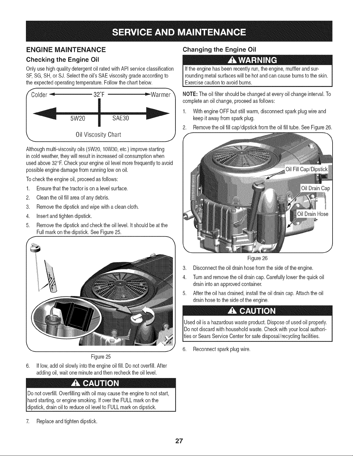
2. Removethe oilfill cap/dipstickfromtheoil fill tube.SeeFigure26.
,,. j
Figure25
6. If low,add oil slowlyintothe engineoil fill. Do notoverfill.After
addingoil, waitoneminuteand then recheckthe oil level.
Figure26
3. Disconnecttheoil drain hosefromthe sideof the engine.
4. Turnand removethe oil draincap. Cardullylowerthequickoil
drainintoan approvedcontainer.
5. After the oil has drained,installtheoil drain cap.Attachthe oil
drainhoseto the sideof theengine.
Usedoil is a hazardouswasteproduct.Disposeof usedoil properly.
IDo notdiscardwithhouseholdwaste.Checkwithyour localauthori-
_tiesor SearsServiceCenterfor safedisposal/recyclingfacilities.
6. Reconnectsparkplugwire.
Donotoverfill.Overfillingwith oil maycausethe engine to not start,
hardstarting,or enginesmoking.If overthe FULLmark onthe
dipstick,drainoil to reduceoil levelto FULLmarkon dipstick.
7. Replaceandtightendipstick.
27
Air Cleaner
Iffilters, orcoversare not installedcorrectlyseriousinjuryor death
couldresultfrombackfire.Do notattemptto start theenginewith
themremoved.
Do notuse pressurizedair or solventsto cleanthe air cleaner
cartridge.
1. Removethe air filtercover.
2. To remove the air filter,liftthe end of the filter.See Figure 27.
E
/Cover
--ngine
Figure27
3. Removethe pre-cleanerfromthe filter.
4. Toloosendebris,gentlytap the filterona hard surface.Ifthe filter
is excessivelydirty, replacewitha newfilter.
5. Washthe pre-cleanerin liquiddetergentandwater.Allowit to
thoroughlyair dry.Do not oil the pre-cleaner.
6. Assemblethe dry pre-cleanerto thefilter.
7. Installthefilter into theengine baseandpushdownuntilthe filter
snapsin place.
8. Installthecover.
Spark Plug
1. Cleanareaaroundthe sparkplug base.Donot sandblastspark
plug. Sparkplugshouldbecleanedby scrapingor wirebrushing
andwashingwith a commercialsolvent
2. Removeand inspectthe sparkplug.Checkgap to makesureit is
setat .030".SeeFigure28.
Electrode Porcelain
!
_ _-'-.030 (.76 ram) gap
Figure28
3. Replacethe sparkplug (Champion®RC12YC)oncea season.
Fuel Filter
Gasolineandits vaporsare extremelyflammableand explosive.Fire
or explosioncancause severeburnsordeath.
• Keepgasolineawayfrom sparks,openflames,pilot lights,heat,
andother ignitionsources.
• Checkfuel lines,tank,cap,and fittingsfrequentlyfor cracks
or leaks.Replaceif necessary.Seea Searsor otherqualified
servicedealerto replacefuel line.
• Beforereplacingthe fuelfilter,drainthe fuel tankor close the fuel
shut-offvalve.
• Replacementpartsmust be the sameand installedinthe same
positionas the originalparts.
• Iffuel spills,waituntilit evaporatesbeforestartingengine.
To Drainthe Fuel:
1. Locatethe fuel filter,whichis routedonthe left sideof the engine
betweenthefuel tankandthe carburetor,andmaybe attachedto
the enginewitha tie strap.
2. Cut the tie strap,if present,then pinchthe in-lineclamp onthe
fuel filterwitha pairof pliers.
3. Slide the clampup thefuel line.
4. Removethe in-linefuel line anddrain thefuel into an approved
container.
To Replacethe Fuel Filter:
1. Beforereplacingthe fuelfilter,drainthe fuel tankor closethe fuel
shut-offvalve.Otherwise,fuelcan leakout and causea fire or
explosion.
28
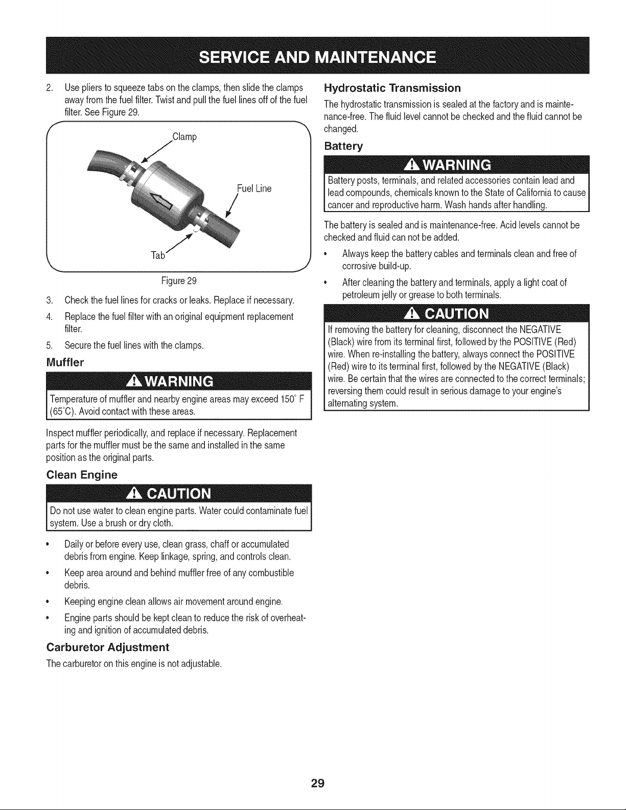
2. Use pliersto squeezetabson theclamps,then slidethe clamps
awayfromthefuel filter.Twistand pullthefuel linesoff of the fuel
filter.SeeFigure29.
f Clamp
FuelLine
/
Figure29
3. Checkthefuel linesfor cracksor leaks.Replaceif necessary.
4. Replacethefuel filterwith anoriginalequipmentreplacement
filter.
5. Securethe fuel lineswiththe clamps.
Muffler
Temperatureof mufflerandnearbyengineareasmayexceed 150° F
(65°0).Avoidcontactwiththese areas.
Hydrostatic Transmission
The hydrostatictransmissionis sealedat thefactory andis mainte-
nance-free.The fluid levelcannotbe checkedandthe fluidcannotbe
changed.
Battery
Batteryposts,terminals,and relatedaccessoriescontainlead and
leadcompounds,chemicalsknownto the Stateof Californiato cause
cancerand reproductiveharm.Washhandsafter handling.
The batteryis sealedand is maintenance-free.Acidlevelscannotbe
checkedandfluid can notbe added.
• Alwayskeepthe batterycablesandterminalscleanand free of
corrosivebuild-up.
Aftercleaningthe batteryand terminals,applya lightcoatof
petroleumjelly orgreaseto bothterminals.
Ifremovingthe batteryforcleaning,disconnectthe NEGATIVE
(Black)wire from itsterminalfirst, followedby the POSITIVE(Red)
wire.Whenre-installingthe battery,alwaysconnectthe POSITIVE
(Red)wire to its terminalfirst,followedbythe NEGATIVE(Black)
wire.Be certainthatthe wiresare connectedto the correctterminals;
reversingthemcouldresultinseriousdamageto yourengine's
alternatingsystem.
Inspectmufflerperiodically,and replaceif necessary.Replacement
partsfor themufflermustbethe sameand installedinthe same
positionas the originalparts.
Clean Engine
Do notuse waterto cleanengineparts.Watercouldcontaminatefuel
system.Use a brushordry cloth.
Dailyor beforeeveryuse,cleangrass,chaff or accumulated
debrisfromengine.Keeplinkage,spring,andcontrolsclean.
• Keeparea aroundandbehindmufflerfreeof any combustible
debris.
• Keepingenginecleanallowsair movementaroundengine.
• Engineparts shouldbe keptcleanto reducethe riskof overheat-
ingand ignitionof accumulateddebris.
Carburetor Adjustment
Thecarburetoron this engineis not adjustable.
29
Neverstorelawntractorwithfuelin tank indoorsor in poorly
ventilatedareaswherefuel fumesmayreachan openflame,spark,
or pilot lightas on a furnace,waterheater,clothesdryer,or gas
appliance,
PREPARING THE ENGINE
IMPORTANT:Fuelleftin the fueltankduringwarmweatherdeterio-
ratesandwill causeseriousstartingproblems.
Topreventgum depositsfromforminginsidetheengine'scarburetor
andcausingpossiblemalfunctionof the engine,the fuel systemmust
beeithercompletelyemptied,or thegasolinemustbetreatedwith a
stabilizerto preventdeterioration.
If usingafuel stabilizer:
a. Readthe productmanufacturer'sinstructionsand recom-
mendations.
b. Add to clean,freshgasolinethe correctamountof stabilizer
for thecapacityof the fuel system.
c. Fill thefuel tank withtreatedfueland run theenginefor 2-3
minutesto get stabilizedfuel intothe carburetor.
If emptyingthefuel system:
a. Do notdrainfuel whentheengineis hot.Allowtheengine
adequatetimeto cool. Drainfuel intoan approvedcontainer
outdoors,awayfromopenflame.
b. Drainany largevolumeof fuelfromthe tankby disconnect-
ingthe fuel linefrom the in-linefuelfilternear theengine.
SeeToDrainthe Fuelonpage 28.
Gasolineis extremelyflammableandcan be explosiveundercertain
conditions.Draingasolinebeforestoringtheequipmentfor extended
periods.Drainfuelonly intoan approvedcontaineroutdoors,away
froman openflame.Allowengine to cool. Extinguishcigarettes,
cigars,pipes,andother sourcesof ignitionpriorto drainingfuel.
Storegasolinein anapprovedcontainerin safelocation.
c. Reconnectthe fuelline and runtheengineuntilit startsto
falter,then usethe choketo keepthe enginerunninguntilall
fuelin the carburetorhasbeenexhausted.
d. Disconnectthe fuel line anddrainany remaininggasoline
fromthe system.
PREPARING THE LAWN TRACTOR
• Cleanandlubricatetractorthoroughlyas describedin the
lubricationinstructions.
• Do notuse a pressurewasheror gardenhoseto cleanyour
unit.
• Storemowerina dry, cleanarea.Do not storenext to
corrosivematerials,suchas fertilizer.
Gasolineis a toxicsubstance.Disposeof gasolineproperly.Contact
yourlocal authoritiesfor approveddisposalmethods.
Removethesparkplug andpour one(1)ounceof engineoil through
the sparkplugholeintothe cylinder.Crankthe engineseveraltimesto
distributetheoil. Replacethe sparkplug.
30
Beforeperforminganytypeof maintenance/service,disengageall
controlsandstoptheengine.Waituntilallmovingpartshavecometo
a completestop.Disconnectsparkplugwireandgroundit againstthe
engineto preventunintendedstarting.Alwayswearsafetyglassesduring
operationorwhileperforminganyadjustmentsor repairs.
Thissectionaddresses minorserviceissues.Tolocate the nearestSears Service Centeror to scheduleservice,simplycontactSears
1. PTO/BladeEngageknobengaged.
2. Parkingbrakenotengaged.
3. Sparkplugwire disconnected.
4. Throttle/Chokecontrollevernot in correct
startingposition.
5. Fueltank empty,or stalefuel.
at 1-800-4-MY-HOME®.
Enginefailsto start
Enginerunserratically
6. BIockedfuel line.
7. Faultysparkplug.
8. Engineflooded.
1. Tractorrunningwith Chokeactivated.
2. Sparkplugwiresloose.
3. Blockedfuel line or stalefuel.
4. Ventin gas cap plugged.
5. Wateror dirt in fuel system.
6. Dirtyair cleaner.
.
Engineoverheats 1. Engineoil levellow 1.
2. Air flowrestricted 2.
Enginehesitatesat high RPMs 1. Sparkpluggap set tooclose 1. Remove
Engineidlespoorly 1. Fouledspark plug 1. Replace
2. Dirtyair cleaner 2. Replace
cleaner.
1. Placeknobin disengaged(OFF)position.
2. Engageparkingbrake.
3. Connectwireto spark plug.
4. PlaceThrottle/Chokeleverto FASTposition.
5. Filltank withclean, fresh(lessthan 30days old)gas.
6. Replacefuel line.See a Searsorotherqualified
servicedealer.Replacefuel filter.Seethe Service
andMaintenancesection.
7. Clean,adjustgap or replaceplug.
8. Crankenginewith throttlein FASTposition.
1. MovetheThrottle/Chokecontrolleverout of the
chokeposition.
2. Connectandtightensparkplugwires.
3. Replacefuel line.See a Searsorotherqualified
servicedealer.Filltankwith clean,freshgasoline
andreplacefuel filter.See the Serviceand Mainte-
nancesection.
4. Clearvent or replacecap if damaged.
5. Drainfueltank. Refillwithclean,fresh gasoline.See
theServiceand Maintenancesection.
Replaceair cleanerpaper elementor cleanfoam
precleaner.
Fillenginewith properamountand type of oil.
Cleangrassclippingsand debrisfromaroundthe
engine'scoolingfinsand blowerhousing.
sparkplug andadjustgap.
sparkplug andadjustgap.
air cleanerelementand/orcleanpre-
Excessivevibration 1. Cuttingbladeslooseor unbalanced 1. Tightenbladeand spindle.Balanceblade.
2. Damaged,dull,or bentcuttingblade 2. Replaceblade.
31
Mowerwill not mulchgrass
Unevencut
1. Enginespeedtoo low.
2. Wetgrass.
3. Excessivelyhighgrass.
4. Dullblade.
1. Decknot leveledproperly.
2. Dullblade.
3. Uneventire pressure.
1. PlaceThrottle/Chokecontrolin FAST(rabbit)
position.
2. Do notmulchwhengrassis wet.
3. Mowonce at a highcuttingheight,then mowagain
at desiredheightor makea narrowercuttingswath.
4. Sharpenor replaceblade.
1. Performside-to-sidedeckadjustment.
2. Sharpenor replaceblade.
3. Checktire pressurein allfour tires.
NEED MORE HELP?
Yotf_l.findthe answerandmoreon.ma_agemyheme,o{om- [o_h'ee!
oFindthisanda[[yourotherproductmanualson[ine.
o Get answers from our team of home experts.
o Get a persona[]zed ma]ntenance plan for your home.
o F]nd ]nformat]on and too[s to he[p w]th home projects.
maHage home
b_o_tght to yo_ by Sears
_!i_iJii!ii@i!iii!iii!iii!iii!iii!iii!iii!iii!iii!iii!iii!iii!iii!iii!iii!iii!iii!iii!iii!iii!iii!iii!iii!iii!iii!iii!iii!iii!iii!iii!iii!iii!iii!iii!iii!iii!iii!iii!iii!iii!iii!iii!iii!iii!iii!iii!iii!iii!iii!iii!iii!iii!iii!iii!iii!iii!iii!iii!iii!iii!iii!iii!iii!iii!iii!iii!iii!iii!iii!iii!iii!iii!iii!iii!iii!iii!iii!iii!iii!iii!iii!iii!iii!iii!iii!iii!iii!iii!iii!iii!iii!iii!iii!iii!iii!iii!iii!iii!iii!iii!iii!iii!iii!iii!iii!iii!iii!iii!iii!iii!iii!iii!iii!iii!iii!iii!iii!iii!iii!iii!iii!iii!iii!iii!iii!iii!iii!iii!iii!iii!iii!iii!iii!iii!iii!iii!iii!iii!iii!iii!iii!iii@
32
Congratulationson makinga smartpurchase.YournewCraftsman@
productis designedandmanufacturedfor yearsof dependableopera-
tion.But likeall products,it mayrequirerepairfromtime to time.That's
whenhavinga RepairProtectionAgreementcansave youmoneyand
aggravation.
Here'swhat the RepairProtectionAgreement*includes:
* Expert service byour 10,000professionalrepairspecialists
o Unlimitedserviceand no chargefor partsand laboron all
coveredrepairs
o Product replacementupto $1500if yourcoveredproductcan't be
fixed
• Discountof 10%from regularprice of serviceand relatedinstalled
partsnotcoveredby theagreement;also,10%off regularpriceof
preventivemaintenancecheck
• Fast help by phone- we call it RapidResolution- phonesupport
froma Searsrepresentative.Thinkof usas a "talkingowner's
manual."
Onceyou purchasethe Agreement,a simplephonecall is all thatit
takesfor youto scheduleservice.Youcan call anytimedayor night,or
schedulea serviceappointmentonline.
The RepairProtectionAgreementis a risk-freepurchase.If youcancel
for any reasonduringthe productwarrantyperiod,wewill provideafull
refund.Or,a proratedrefundanytimeafterthe productwarrantyperiod
expires.Purchaseyour RepairProtectionAgreementtoday!
Somelimitationsand exclusionsapply. For pricesand additional
informationin the U.S.A.call 1-800-827-6655.
*Coverage in Canadavaries on some items.Forfull details call
Sears Canadaat 1-800-361-6665.
Sears Installation Service
ForSearsprofessionalinstallationof homeappliances,garagedoor
openers,waterheaters,andothermajorhomeitems,in the U.S.A.or
Canadacall 1-800-4-MY-HOME®.
33
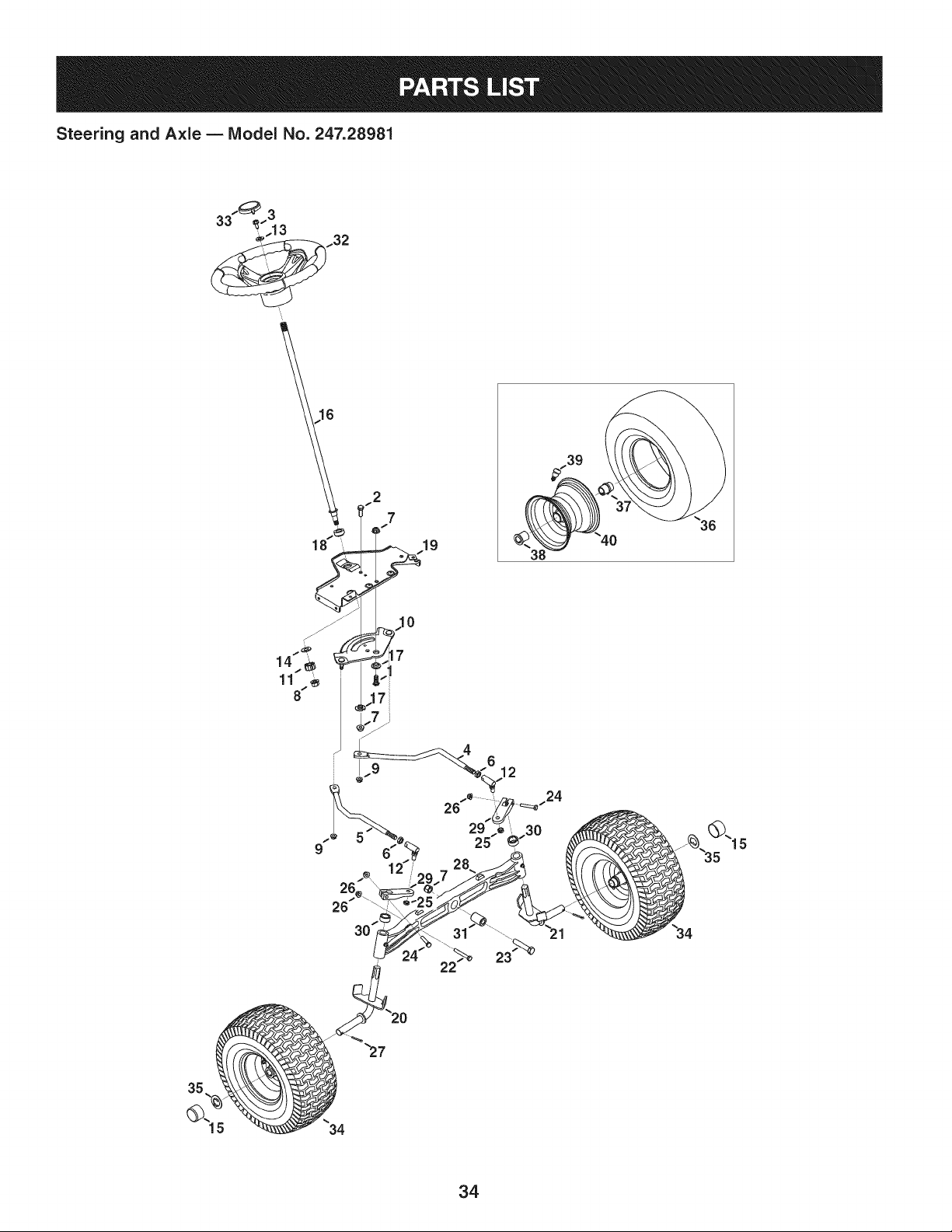
Steering and Axle B Model No. 247.28981
2
7
19
9
17
6
12
23
34

Steering and Axle B IViodel No. 247.28981
710-04095 HexHeadScrew,3/8-16:1.00 638-04028-0637 LHAxle Assembly
2 710-0514 HexHeadScrew,3/8-16:1.00 22 710-0395 HexHeadScrew,5/16-18:2.25
3 710-0643 HexHeadScrew,5/16-18:1.00 23 710-0859 HexHeadScrew,3/8-16:2.50
4 711-04998 LH DragLink 24 710-3180 HexHeadScrew,5/16-18:1.75
5 711-04999 RHDragLink 25 912-0214 HexlockNut,3/8-24
6 912-0240 JamNut,7/16-20 26 712-04063 FlangelockNut,5/16-18
7 712-04065 FlangelockNut,3/8-16 27 714-0162 CotterPin,5/32:1.25
8 712-0459 FlangelockNut,7/16-20 28 719-04413A PivotBarAxle
9 712-3004A FlangelockNut,5/16-18 29 748-04065-0637 SteeringBlock
10 717-1550F SteeringGear 30 748-04068 Spacer,.71IDX .125OD X .56LG
11 717-1554 SteeringPinionGear 31 750-05280 Spacer,.385X 1.00X 1.5075
12 923-0448A BallJoint,7/16-20 32 631-04415 SteeringWheel
13 936-3004 FlatWasher,.406X .875X .105 33 731-06825 SteeringWheelCap
14 736-3084 FlatWasher,.51X 1.12X .06:HT 34 634-04406-0961 WheelAssembly
15 731-05674 BumperCap 35 736-04228A FlatWasher,.7811Dx 1.5900D
16 738-04263 SteeringShaft,.625OD X 24.25LG 36 734-1731-0901 Tire
17 738-04363 ShoulderSpacer,.385X1.25X .3025 37 741-0990B FlangeBearing,.7601D
18 741-04237B Hex FlangeBearing5/8 PM 38 741-0516B FlangeBearing,.760x 1.00x 1.20LG
19 783-06043-0637 SteeringSupportBracket i39 934-0255 TubelessAir Valve
20 638-04022-0637 RHAxle Assembly i40 634-04405-4042 RimAssembly
35
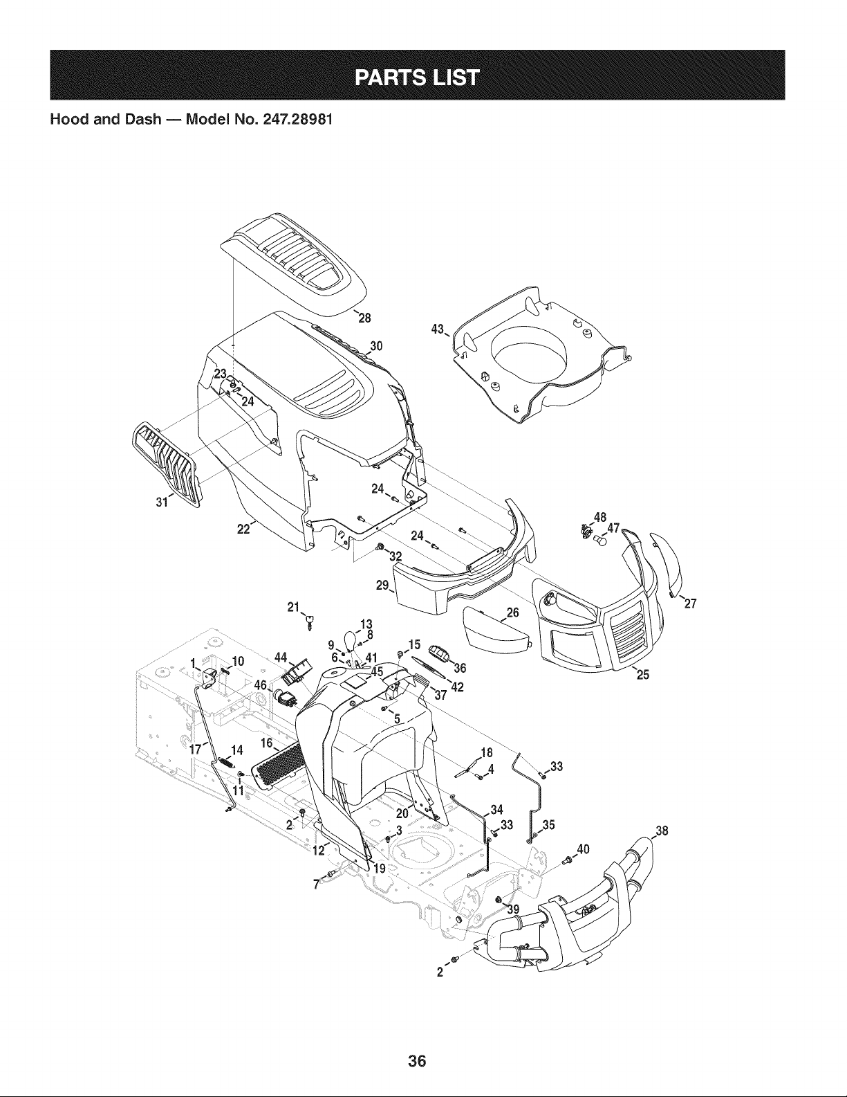
Hood and Dash B IViodel No. 247.28981
3O
31
48
13
8
15
38
36

Hood and Dash B Model No. 247.28981
631-04353P DashLever 931-07457 Grill
2 710-04484 TaptiteScrew,LockWasher,5/16-18:.750 i26 731-07458 RH Lens
3 710-0599 TaptiteScrew,LockWasher,1/4-20:0.500 i27 731-07459 LH Lens
4 710-0895 Hi-LoScrew,LockWasher,1/4-15:0.750 i28 931-07461 HoodScoop
5 710-0896 Screw,LockWasher,1/4-14:0.625 i29 731-07467 LowerGrill
6 710-1017 Screw,1/4-14:0.625 i30 731-07469 LH HoodScoop
7 710-1611B TaptiteScrew,5/16-18:0.750 i31 731-07470 RH HoodScoop
8 710-3217 MachineScrew,#8-32:0.375 i32 738-04091A ShoulderScrew,.43X.29:TT:5/16-18
9 712-0142 HexNut,#8-32:GRA i33 710-0642 TaptiteScrew,1/4-20:0.750
10 714-04040 Bow-tieCotterPin i34 747-05049 RHTankSupportRod
11 726-3046 RatchetClip:.250DIA i35 747-05050 LHTankSupportRod
12 731-07456 Dash i36 751-0603A FuelCap
13 731-07550 ControlKnob i37 951-10573 FuelTank,2.75 Gallons
14 732-04580 ExtensionSpring,.500DIAX 2.733LG i38 689-00157 GuardAssembly
15 735-0271A Bumper i39 712-04065 FlangelockNut,3/8-16
16 735-04076 AccessoryNet i40 738-0143 ShoulderBolt,.496x .336:3/8-16
17 747-05280 ControlRodLatch i41 946-04556 Throttle/ChokeControl
18 747-1196 LeverRod i42 735-04170 FuelTankGasket
19 783-04285F-0637RHDash SupportPlate i43 731-07495 P-StylePlen
20 783-04323F-0637LH DashSupportPlate 44 725-04992 SwitchKey Module
21 625-04124 Key(Set of 2) i45 925-04036C HourMeter
22 683-04618-0691 HoodAssembly i46 725-04258 PTOSwitch
23 710-04187 Hi-loScrew,LockWasher,1/4-15:0.50 i47 925-0963 MiniatureLamp,12V
24 710-05108 Screw,LockWasher,1/4DIA:.750 i48 925-1649 LampSocket
37
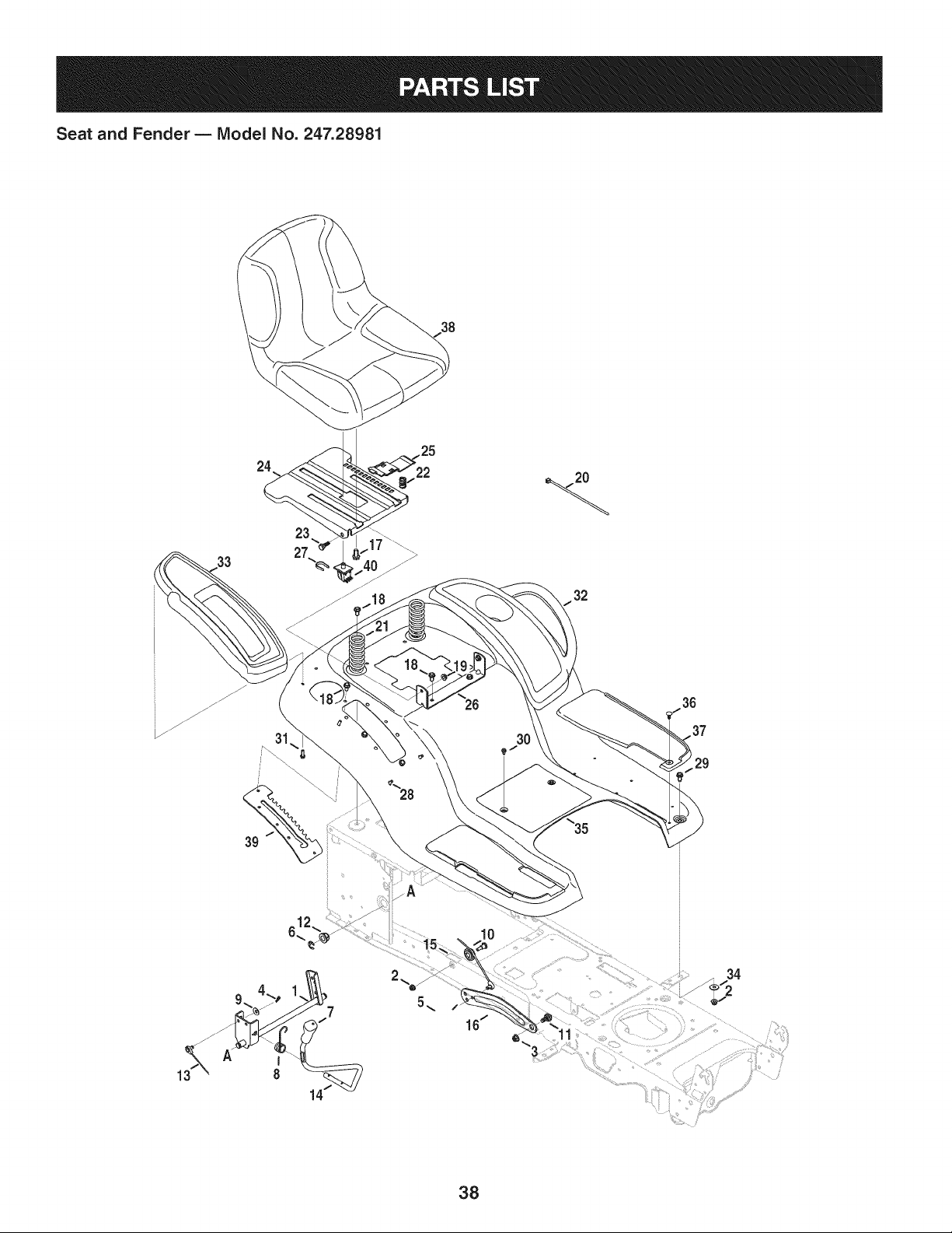
Seat and Fender B Model No. 247.28981
38
24
23
33 27
31 30
612_
29
38

Seat and Fender B Model No. 247.28981
683-04223-0637 Lift ShaftAssembly 732-04563 CompressionSpring,.68X 1.065X .055
2 712-04063 FlangelockNut,5/16-18 i23 938-0296 ShoulderScrew,.437X .268:5/16-18
3 712-04065 FlangelockNut,3/8-16 i24 783-06049-0691 Seat MountingBracket
4 914-0104 CotterPin,.072DIA.X 1.13LG i25 783-06050 SeatAdjustmentLever
5 714-04040 Bow-TieCotterPin i26 783-06088-0691 Seat PivotBracket
6 716-0106A E-Ring,.625DIA.SHAFT i27 783-06448 SwitchRetainerClip
7 720-04150 HandleGrip i28 710-04187 Hi-LoScrew,LockWasher,1/4-15:0.50
8 732-0874 TorsionSpring i29 710-0451 CarriageBolt,5/16-18:.750
9 736-0105 SpringWasher,.401X .870X .063 i30 710-0599 TaptiteScrew,LockWasher,1/4-20:0.500
10 738-0138A ShoulderScrew, .437X .470:5/16-18 i31 710-0895 Hi-LoScrew,LockWasher,1/4-15:0.750
11 938-0380 ShoulderBolt,.500x.270:3/8-16 i32 731-05837 LH FenderCover
12 941-0225 HexFlangeBearing i33 731-06754 RHFenderCover
13 i746-0968 LiftCable, 16.16LG i34 736-3078 FlatWasher,.344X 1.00X .063HDN
14 i747-04962A Lift Handle i35 783-06118-0691 Fender
15 i756-04331 PulleyRollerCable i36 726-3046 RatchetClip
16 i783-05546A-0637LiftArm i37 735-04137 LH FootPad
17 710-04482 HexHeadFlange,3/8-16:.875 -- 735-04139 RHFootPad
18 710-04484 TaptiteScrew,LockWasher,5/16-18:.750 38 757-04127 Seat
19 712-3004A FlangelockNut,5/16-18 i39 783-06181-0637 LiftBracket
20 i725-0157 CableTie, 3/16X .05X 7.4 i40 925-05013 Seat Switch
21 732-04561 CompressionSpring,1.71X3.735X .238
3g
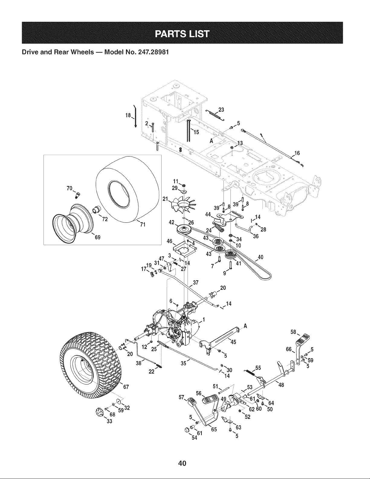
Drive and Rear Wheels B IViodel No. 247.28981
23
7O
69
71
39/I
2O
4O
10
22
4O

Drive and Rear Wheels B Model No. 247.28981
918-0319 HydroTransmission
2 710-0176 HexHeadScrew,5/16-18:2.75
3 710-0227 Screw,indentedWasher,#8-18:0.500
4 710-0351 Screw,#10-16:0.500
5 710-04484 TaptiteScrew,indentedWasher,5/16-18:.750
6 710-0653 TaptiteScrew,indentedWasher,1/4-20:0.375
7 710-1007 TaptiteSeresScrew,:3/8-16:1.500
8 710-1325 TaptiteScrew,indentedWasher,1/4-20:1.625
9 710-3011 HexHeadScrew,3/8-16:2.25
10 912-0240 JamNut,7/16-20
11 912-0346 JamlockNut, 1/2-20
12 712-04063 FiangelockNut,5/16-18
13 912-0431 FlangelockNut,3/8-16
14 914-0111 CotterPin,3/32:1.0
15 725-0157 CableTie.3/16X .05X 7.4
16 725-04791A JumperHarness
17 725-1644 ShortSpringSwitch
18 926-0154 PushMountCableTie 7.5LG
19 926-0320 InsulatorNutPlate
20 731-05299A Sleeve,.765ID X 1.500LG
21 731-06098 HydroFan
22 932-0209 ExtensionSpring,.48ODX 2.03
23 732-04606 ExtensionSpring,.500DIAX 12.6LG
24 732-04624 ExtensionSpring,1.00DIA X 4.75
25 732-0716D ExtensionSpring,.59ODX 4.00 LG
26 732-0729 WireRing
27 732-3118 ExtensionSpring,.375OD X 1.44LG
28 936-0264 FiatWasher,.330X .630X .0635
29 736-04263 LockWasher
30 936-3008 FiatWasher,.344 X .750X .120
31 736-3010 FiatWasher,.407X .812X .135
32 736-0430 FiatWasher,.50 x 1.59x .062
33 731-2290A HubCap
34 738-04420 ShoulderSpacer,1.375X .380X .183
35 747-04139 BrakeRod
36 747-04957A FootpedalBypassTransmissionRod
747-04979 HydroControlRod
i38 747-04991 HydroBypassRod
i39 750-04456 Spacer,260X .372X 1.420LG
i40 954-04207 V-Belt,4L X 78.9POLY
i41 756-04224 FlatIdlerPulley,2.75OD
i42 756-04308 inputPulley,4.13DIA
i43 756-04325 V IdlerPulley,X3.06
i44 783-06027A CenterIdlerBracket
i45 783-06133-0637 HydroMountingBracket
i46 783-06260-0637 BeltDisengageSupportBracket
i47 783-1019B SwitchActuatorBracket
i48 647-04152A BrakeControlAssembly
i49 683-04488 HydroPedalBracketAssembly
i50 710-0604A TaptiteScrew,indentedWasher,5/16-18:0.625
i51 711-05068 ClevisPin,5/16X 3.985
i52 712-04065 FlangelockNut,3/8-16
i53 714-04040 Bow-TieCotterPin
i54 726-0214 PushCap
i55 732-04587 ExtensionSpring,.63 DIAX 4.95LG
56 735-04118A ForwardPedalPad
i57 735-04135 ReversePedal Pad
i58 735-04136 BrakePedalPad
i59 736-0242 BellWasher,.340X .872X .060
i60 938-0380 ShoulderBolt,.500X .270:3/8-16
i61 741-0495 FlangeBearing,.630 IDX.695OD X .60
i62 748-04203 CruiseLatch
63 783-05914 PedalSupportBracket
i64 783-05940 PedalSupportBracket,5/8
i65 783-06059-0637 DrivePedalBracket
i66 783-06103A-0637BrakePedalBracket
i67 634-0177-0961 WheelAssembly
68 710-0627 HexHeadScrew,5/16-24:.750
i69 634-04369-4042 RimAssembly
i70 934-0255 TubelessAir Valve
i71 734-1873-0901 Tire
i72 941-0490 Axle Hub
41
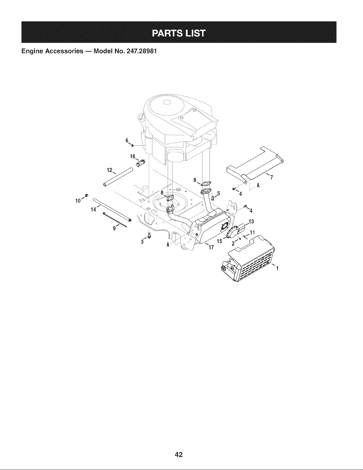
Engine Accessories B IViodel No. 247.28981
16
3
17
42

Engine Accessories B IViodel No. 247.28981
683-04549-0637 MulfflerShieldAssembly
2 710-0227 Screw,IndentedWasher,#8-18:0.500
3 710-04683 TaptiteScrew,IndentedWasher,3/8-16:1.000
4 710-0599 TaptiteScrew,IndentedWasher,1/4-20:0.500
5 710-1314A SocketHeadScrew,5/16-18:.750
6 712-0271 SeresNut, 1/4-20
7 783-06378 HeatShield
8 721-0460 ExhaustGasket
9 725-0157 CableTie,3/16X .05X 7.4
10 726-0205 HoseClamp,.490DIA.
11 728-04000 Rivet,.188DIAX .300 L
12 751-3141-14 OilDrainExtensionHose
13 751-0564B MufflerDeflector
14 751-10349 FuelHose
15 751-10353 LongMufflerDeflector
16 951-10517A OilDrain
17 751-10542A MufflerDeflector
43
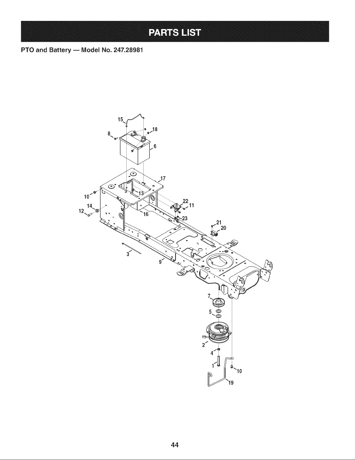
PTO and Battery B IViodel No. 247.28981
3
22
11
_'_19
44

PTO and Battery B IViodel No. 247.28981
710-04379A HexHeadScrew,7/16-20:3.50
2 917-04174A ElectricPTOClutch
3 725-0157 CableTie,3/16x .05x 7.4
4 936-0171 LockWasher,7/16
5 736-0277 FiatWasher,1.031x 1.620x .095
6 725-05088 Battery
7 756-0978B ElectricPTOEnginePulley
8 710-04666 HexHeadFlange,1/4-20:.75
9 683-04469A-0691Frame
10 710-04484 TaptiteScrew,indentedWasher,5/16-18:.750
11 710-0599 TaptiteScrew,indentedWasher,1/4-20:0.500
12 710-3005 HexHeadScrew,3/8-16:1.25
13 712-04065 FlangelockNut,3/8-16
14 738-04058 ShoulderSpacer,.38X 1.0X .70
15 747-04121A BatteryHolderRod
16 783-0349-0637 BatteryTray
17 783-06089-0637 SeatFrameBracket
18 712-0271 SeresNut, 1/4-20
19 747-05195 BeltKeeperRod
20 725-04363 interlockSwitch
21 738-04237A ShoulderScrew,#10-32:.500
22 725-04439 Solenoid,12V
23 712-04064 FiangelockNut, 1/4-20
45
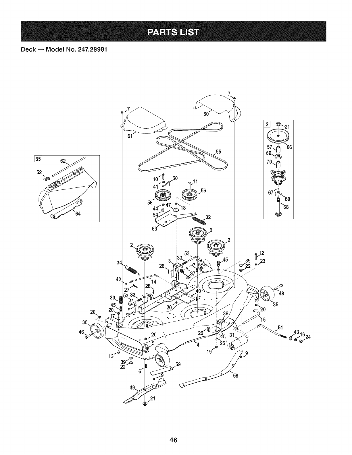
Deck B IViodel No. 247.28981
[]
62
42
10 ® _50
56
2O
59
25
58
21
[] _'_21
57._ 66
69.._
70-. 0
67"_..69
46

Deck B Model No. 247.28981
96606 RetainerHookBracket 734-0973 RearDeckWheel
2 918-04825B SpindleAssembly i37 936-0119 LockWasher,5/16
3 683-0254B-4028 DeckHangerBracketAssembly i38 936-0179 FiatWasher,.531X 1.25X .100
4 983-04561-4028 DeckAssernbly i39 736-0225 LockWasher,5/8
5 703-3279-4028 DeflectorChuteStop i40 936-0275 FiatWasher,.344X .688X .065
6 710-04095 HexHeadScrew,3/8-16:1.00 i41 936-0300 FiatWasher,.406X .875X .059
7 710-04484 TaptiteScrew,indentedWasher,5/16-18:.750 i42 936-0314 ThrustWasher,.375X.70X.030
8 710-0528 HexHeadScrew,5/16-18:1.25 i43 736-0317 BellWasher,.63X 1.25X .18
9 710-0599 TaptiteScrew,indentedWasher,1/4-20:0.500 i44 736-3010 FiatWasher,.407X.812X.135
10 710-1008 TaptiteSernsScrew,3/8-16:1.875 i45 737-04003D WaterNozzle
11 710-3011 HexHeadScrew,3/8-16:2.25 i46 938-0373 ShoulderBolt,.496X 1.525:3/8-16
12 710-3103 HexHeadScrew,5/16-18:2.00 i47 738-04162A ShoulderSpacer,.8840X.190
13 710-3178 CarriageBolt,3/8-16:0.75 i48 938-3056 ShoulderBolt, .496X 2.50:3/8-16
14 711-05078 DeckSupportRod i49 942-04053C 2-in-1CuttingBlade
15 911-3314 RollerPin i50 747-04530 BeltKeeperRod
16 912-0206 HexNut, 1/2-13 i51 747-05067A DeckLiftRod
17 712-0229 PushNut,3/8 i52 732-04372 TorsionSpring
18 912-0240 JamNut,7/16-20 i53 747-1116 DeckReleaseHandleRod
19 712-04063 FlangelockNut,5/16-18 54 750-3119 Spacer,.406ID X 1.00ODX .38
20 712-04065 FlangelockNut,3/8-16 i55 954-04240 V-Belt
21 712-0417A FlangeNut,5/8-18 i56 756-04129B IdlerPulley,4.25"DIA
22 912-0641 Hex Nut,M16-1.5DiN936 i57 750-1096 Spacer,.800x 1.100x 1.53LG
23 912-3010 Hex Nut,5/16-18 i58 783-04414A-4028CenterDeck Skirt
24 712-3083 HexlockNut, 1/2-13 59 783-04415-4028 RH DeckSkirt
25 914-0111 CotterPin, 3/32:1.0 i60 783-05280-4028 LH BeltCover
26 753-04070 LynchPin,.1875 i61 783-05281-4028 RH BeltCover
27 714-04043 Bow-TieCotterPin i62 711-04565 HingePin
28 914-0470 CotterPin, 1/8X 1.25 i63 783-06361-0637 IdlerBracket
29 917-04074 DeckGear i64 783-05030 ChuteBracket
30 921-04041 WaterNozzleAdaptor i65 631-04070A ChuteDeflector
31 731-05679 FrontRoller 66 756-04216 DeckPulley,5.39 DIA
32 732-04649 ExtensionSpring,1.00D X 6.10LG i67 937-3000 LubeFitting
33 732-04652 CompressionSpring,.535ODX 1.751LG i68 738-0976 SpindleShaft,4.1250LG.
34 732-0934 ExtensionSpring,1.15ODX 5.99 LG i69 941-0919 BallBearing,.7871DX 1.850DX.551
35 734-04155 FrontDeckWheel i70 748-0434 Spacer,.750x 1.150x .230LG
4.7
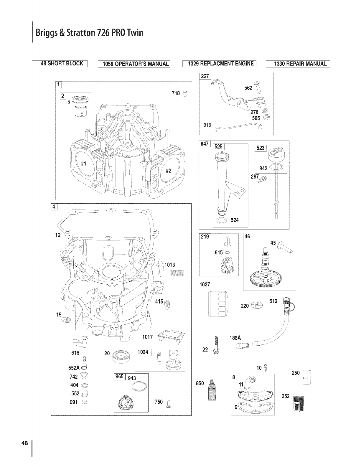
Briggs& Stratton 726PROTwin
48 SHORTBLOCK I 1058OPERATOR'SMANUAL
1329REPLACMENTENGINEI 1330REPAIRMANUALI
3
616
S52A6
742 \,_
404 _<:_>
U _
552_>
691 _
/
1017
@_ 750 i
......278 #_#
505 <__
i 212 __ '%,_
i
, i
i523
615 o
1027
45
_._ 512 _220 _,_.;_._
//
186A ...._ .................
C_ _.................
850
io_
9_ ......_)
250
252
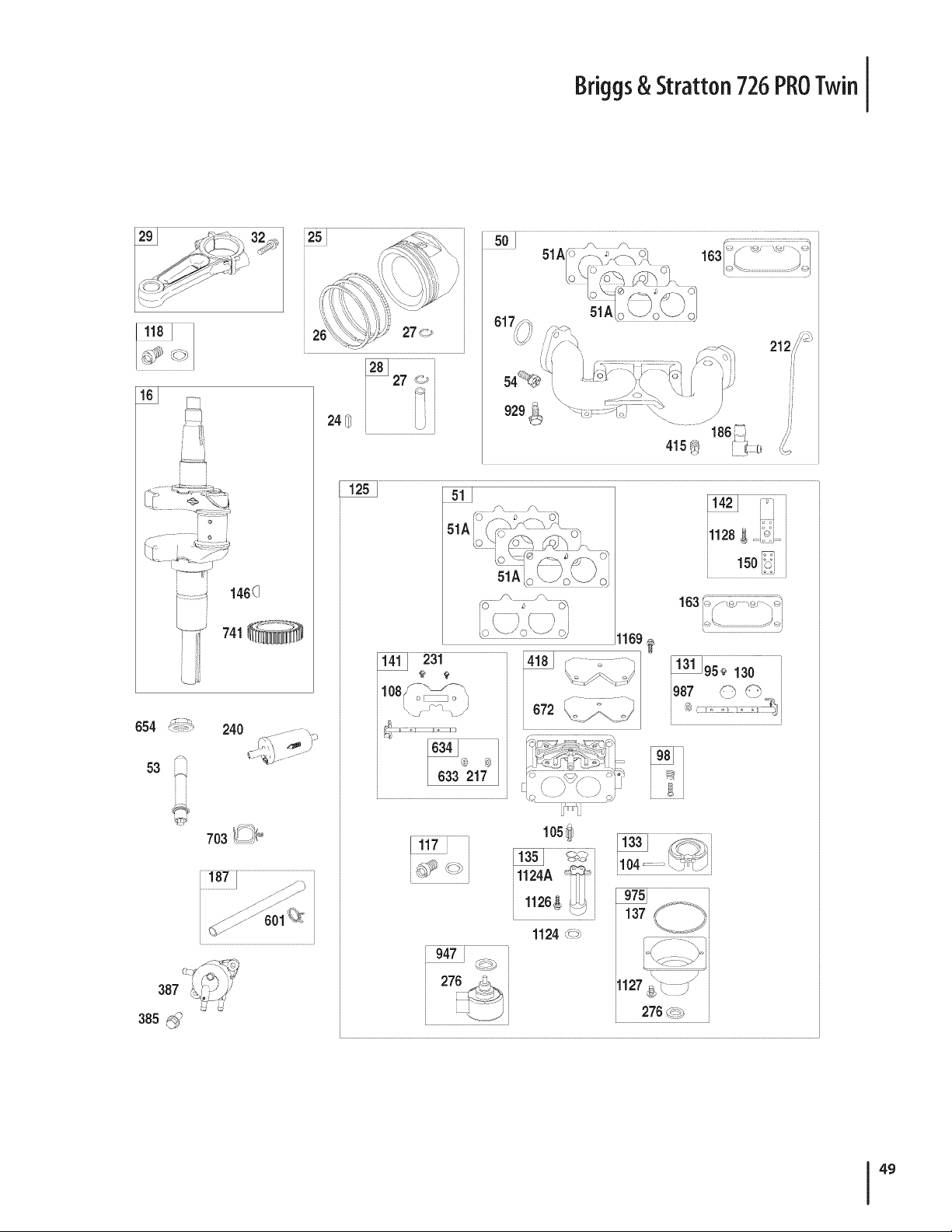
Briggs& Stratton 726PROTwin
741
654 240
53 _
i i
703 _ _
387 %_ +_
385
24_ L
]
415®
11695
_231 i418 ....
66_343 _ 6?,
217_
, J
150iioi....
L_ J
idk.... J_j
l l_,_ _;_ _'il l _ i
<c, \- S \-.Jc_i- , _ ,
276 _,+ i
L£ __Ji
lOS_
1124A "+_+
iiii
\. J
1124_
137
i1127......... s
270d+.
49
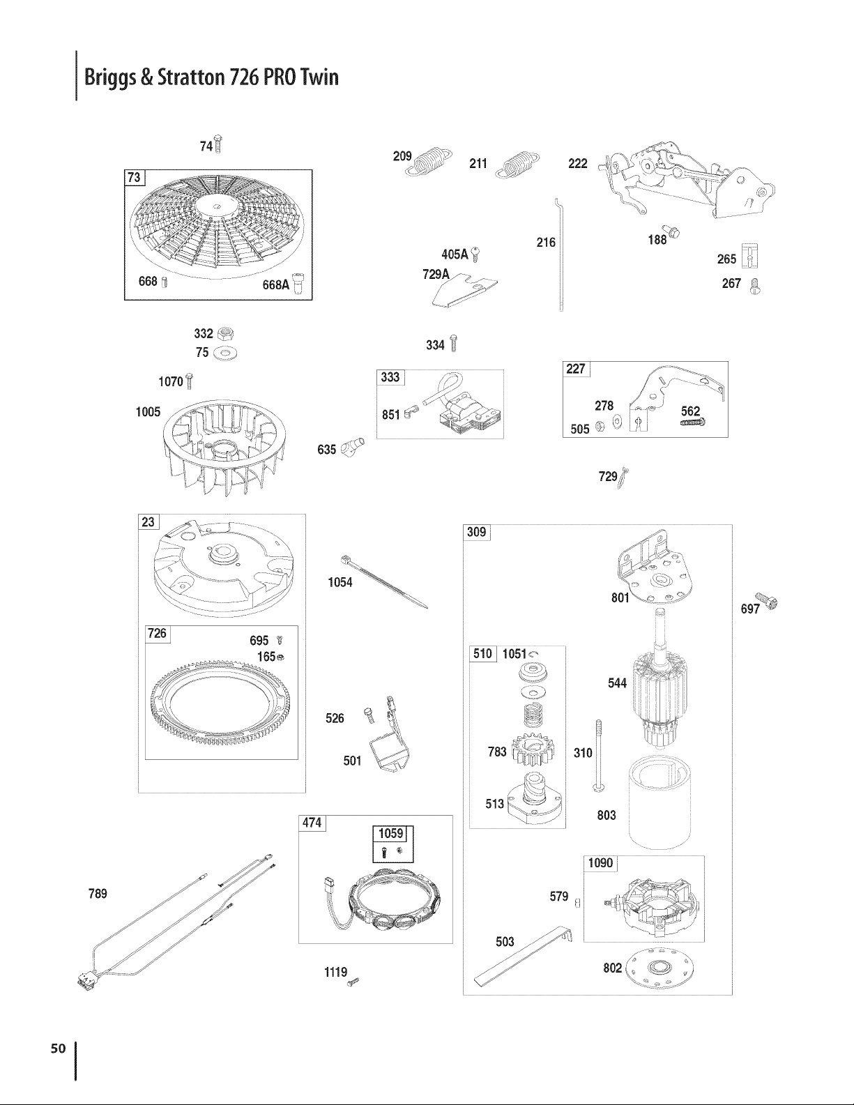
Briggs& Stratton 726PROTwin
74_
332 _
1070_
1005
211 _:,,Y
aosA_
334 't!
216
222
562
265
267_
789
695 _:_
1054 _
526
501
1119
80
783
544
310
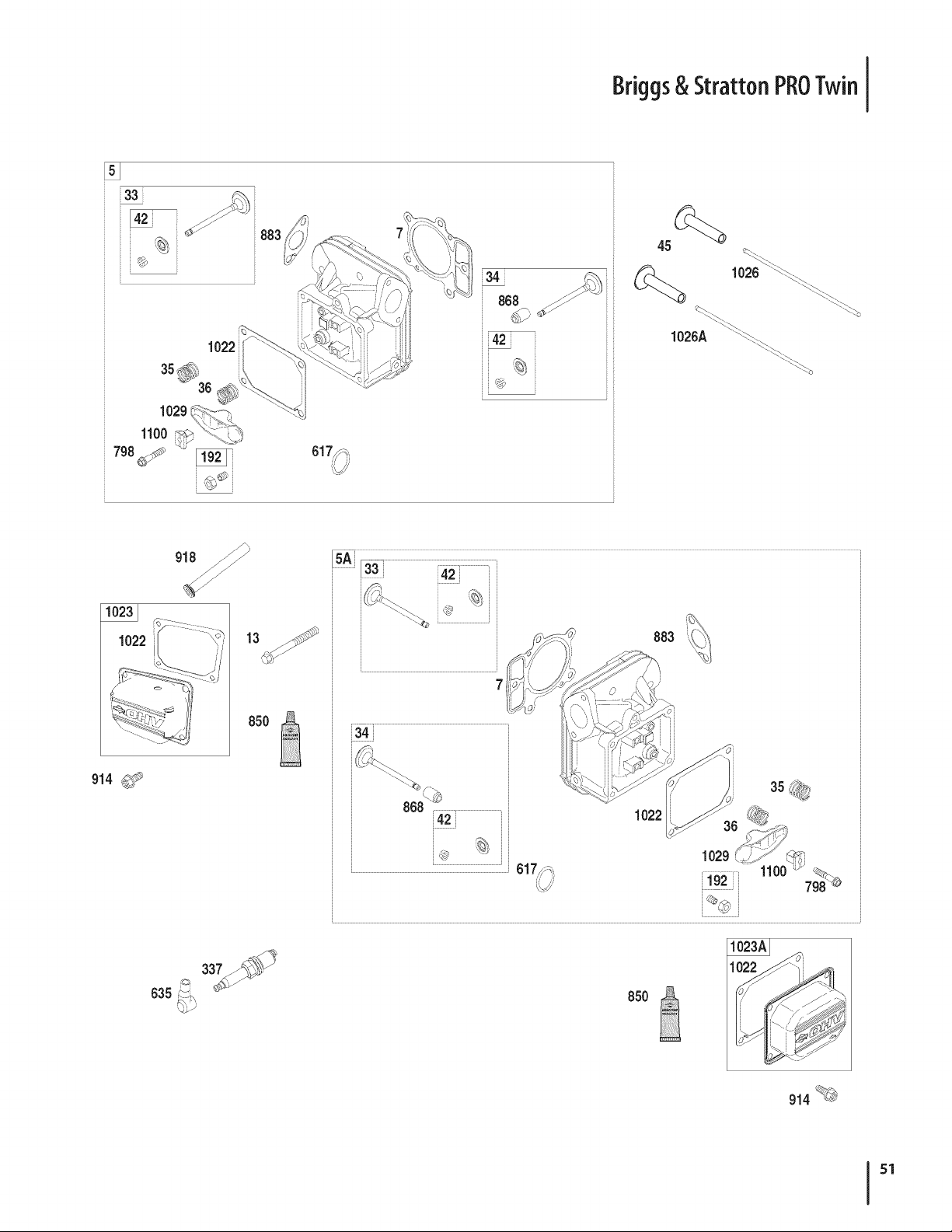
Briggs& Stratton PROTwin
_33i
t
1100 _>
883
_68 _/S _
1026 ...._
1026A _yy_
914 _
13
850
883
1022
35 i_!_:_
i Ji
635
850
914 _
51
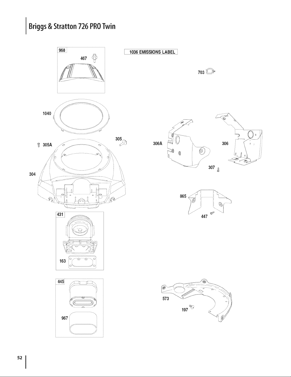
Briggs& Stratton 726PROTwin
1036EMiSSiONSLABEL
703
1040 // \
f_
304
306A
307
306
\
163 _'/" _ _ _
\ ...................
665
447
/ ..............................................-\
967 "
573
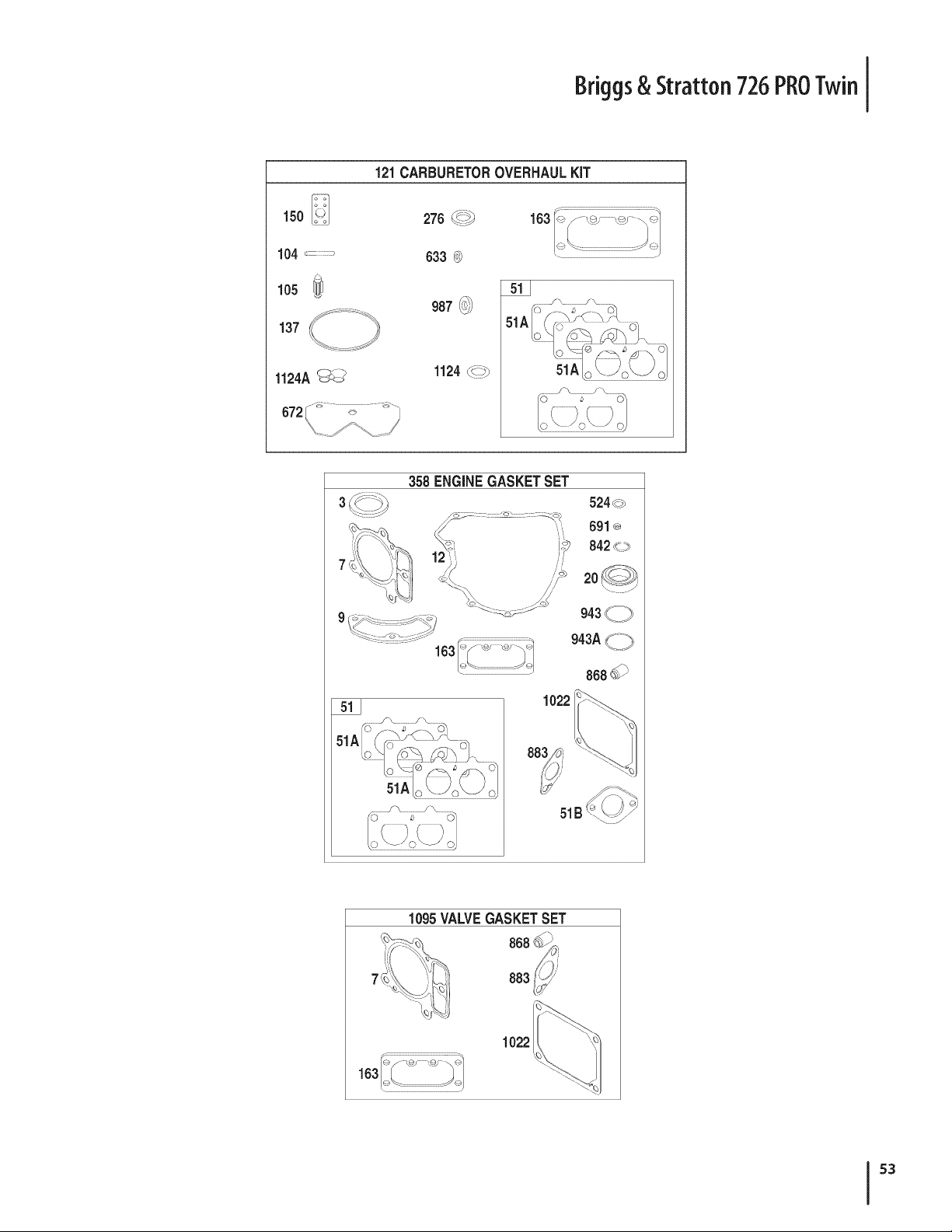
Briggs& Stratton 726PROTwin
150 _
104 ........
105
137
1124A_
121CARBURETOROVERHAULKiT
633 0 L_<_.................................._ _
987 _
1124_ _
358 ENGINEGASKETSET
524_>
691_
842__>
868_
1022
51B
1095VALVEGASKETSET
7
163I _ _ _ _
$3

Briggs& Stratton 726PROTwin
D _ 0 IJ
BS-793564 CylinderAssembly
2 BS-499585 Kit-Bushing/Seal(MagnetoSide)
3+ BS-391086s Seal-Oil(MagnetoSide)
4 BS-796307 Sump-Engine
5 BS-796270 Head-Cylinder(Cylinder#1)
5A BS-796271 Head-Cylinder(Cylinder#2)
7+& BS-693997 Gasket-CylinderHead
8 BS-792185 BreatherAssembly
9+ BS-690937 Gasket-Breather
10 BS-697551 Screw(BreatherAssembly)
11 BS-792184 Tube-Breather
12+ BS-697227 Gasket-Crankcase
13 BS-793988 Screw(CylinderHead)
15 BS-690946 Plug-OilDrain
16 BS-796540 Crankshaft
20+ BS-795387 Seal-Oil(PTOSide)
22 BS-694966 Screw(CrankcaseCover/Sump)
23 BS-691053 Flywheel
24 BS-222698s Key-Flywheel
25 BS-793560 PistonAssembly(Standard)
BS-793563 PistonAssembly(.020"Oversize)
26 BS-793561 RingSet (Standard)
BS-792073 RingSet (.020"Oversize)
27 BS-690975 Lock-PistonPin
28 BS-696581 Pin-Piston
29 BS-796209 Rod-Connecting
32 BS-690976 Screw(ConnectingRod)
33 BS-793357 Valve-Exhaust
34 BS-793556 Valve-Intake
35 BS-694865 Spring-Valve(Intake)
36 BS-694865 Spring-Valve(Exhaust)
42 BS-499586 Keeper-Valve
45 BS-690977 Tappet-Valve
46 BS-796853 Gear-Cam
48 BS-797093 ShortBlock
50 BS-695241 Manifold-Intake
51+ BS-795123 Gasket-intake
51A BS-690950 Gasket-intake
51B BS-690949 Gasket-intake
D _ O 0
BS-690951 Stud(Carburetor)
54 BS-699816 Screw(IntakeManifold)
73 BS-494439 Screen-Rotating
74 BS-698425 Screw(RotatingScreen)
75 BS-691056 Washer(Flywheel)
95 BS-690718 Screw(ThrottleValve)
98 BS-699721 Kit-IdleSpeed
104% BS-694918 Pin-FloatHinge
105 BS-698537 Valve-FloatNeedle
108 BS-699723 Valve-Choke
117 BS-842630 Jet-Main(Standard)
118 BS-797477 Jet-Main(HighAltitude)
121 BS-792455 Kit-CarburetorOverhaul
125 BS-796997 Carburetor
130 BS-690993 Valve-Throttle
131 BS-499805 Kit-ThrottleShaft
133 BS-699724 Float-Carburetor
135 BS-699729 Tube-FuelTransfer
137% BS-690994 Gasket-FloatBowl
141 BS-796228 Kit-ChokeShaft
142 BS-699726 Nozzle-Carburetor
146 BS-690979 Key-Timing
150 BS-690995 Gasket-Nozzle
163+% BS-691001 Gasket-AirCleaner
165 BS-693148 Nut(RingGear)
186 BS-795985 Connector-Hose
187 BS-791766 Line-Fuel(Cutto RequiredLength)
188 BS-697551 Screw(ControlBracket)
192 BS-690083 Adjuster-RockerArm
197 BS-697820 Screw(BackPlate)
209 BS-796658 Spring-Governor(Yellow/Brown)
211 BS-796225 Spring-GovernedIdle(Orange)
212 BS-695238 Link-Throttle
216 BS-796229 Link-Choke
217 BS-695409 Spring-ChokeReturn
219 BS-793338 Gear-Governor
+ -- Includedin EngineGasketSet,Key.No.358
& --Included in ValveGasketSet,KeyNo. 1095
% -- Includedin CarburetorOverhaulKit, KeyNo. 121

Briggs& Stratton 726PROTwin
D _ W O
BS-690412 Washer(GovernorGear)
221 BS-841026 Cup-Governor
222 BS-796226 Bracket-Control
227 BS-796223 Lever-GovernorControl
231 BS-690718 Screw(ChokeValve)
239 BS-792028 Switch-OilPressure
240 BS-695666 Filter-Fuel
250 BS-690957 Retainer-Breather
252 BS-794389 Collector-Oil
265 BS-691024 Clamp-Casing
267 BS-695134 Screw(CasingClamp)
276% BS-695410 Washer-Sealing
278 BS-792651 Washer(GovernorControlLever)
287 BS-697551 Screw(DipstickTube)
304 BS-797407 Housing-Blower
305 BS-691005 Screw(BlowerHousing)
305A BS-790690 Screw(BlowerHousingto IntakeElbow)
306 BS-796541 Shield-Cylinder(Cylinder#2)
306A BS-796852 Shield-Cylinder(Cylinder#1)
307 BS-697551 Screw(CylinderShield)
309 BS-499521 Motor-Starter
310 BS-691263 Screw(StarterMotor)
332 BS-691059 Nut(Flywheel)
333 BS-691060 Armature-Magneto
334 BS-691061 Screw(MagnetoArmature)
337 BS-491055s Plug-Spark
358 BS-694012 GasketSet-Engine
385 BS-797409 Screw(FuelPump)
387 BS-808656 Pump-Fuel
404 BS-690442 Washer(GovernorCrank)
415 BS-794903 Plug(Oil PressureSwitchHole)
418 BS-795912 Plate-Carburetor
431 BS-792297 Elbow-intake
445 BS-792105 Filter-AirCleanerCartridge
447 BS-691003 Screw(AirGuideCover)
467 BS-790697 Knob-AirCleaner
474 BS-696458 Alternator
501 BS-797375 Regulator
503 BS-691532 Strap-Starter
D _ O
BS-691029 Nut (GovernorControlLever)
510 BS-794360 Drive-Starter
513 BS-692024 Clutch-Drive
523 BS-691036 Dipstick
524+ BS-691032 Seal-DipstickTube
525 BS-691037 Tube-Dipstick
526 BS-697551 Screw(Regulator)
544 Armature-Starter(ForReplacement,Order
StarterMotor499521,Reference309)
552 BS-796638 Bushing-GovernorCrank
552A BS-690553 Bushing-GovernorCrank
562 BS-690311 Screw(GovernorControlLever)
573 BS-790444 Plate-Back
579 BS-691029 Nut(StarterCable)
601 BS-691038 Clamp-Hose(Black)
615 BS-698290 Retainer-GovernorShaft
616 BS-691045 Crank-Governor
617 BS-697891 Seal-ORing(IntakeManifold)(Red)
633% BS-699813 Seal-Choke/ThrottleShaft
634 BS-698779 Spring/SealAssembly
635 BS-66538s Boot-SparkPlug
654 BS-690958 Nut(Carburetor)
668+ BS-691215 Spacer(RotatingScreen)
668A BS-691500 Spacer(RotatingScreen)
672 BS-690234 Gasket-CarburetorPlate
691+ BS-790574 Seal-GovernorShaft
695 BS-693149 Screw(Ring Gear)
697 BS-690372 Screw(DriveCap)
703 BS-691010 Clip
718 BS-690959 Pin-Locating
726 BS-499612 Gear-Ring
729 BS-797454 Clip-Wire
741 BS-690980 Gear-Timing
742 BS-690328 Retainer-ERing(GovernorCrank)
750 BS-796208 Screw(Oil PumpCover)
783 BS-695708 Gear-Pinion
+ -- Includedin EngineGasketSet,Key.No.358
& --Included in ValveGasketSet,KeyNo. 1095
% -- Includedin CarburetorOverhaulKit, KeyNo. 121
55

Briggs& Stratton 726PROTwin
D _ O IJ
BS-797424 Harness-Wiring
798 BS-697890 Screw(RockerArm)
801 BS-691283 Cap-Drive
802 BS-691286 Cap-End
803 Housing-Starter(ForReplacement,Order
StarterMotor499521,Reference309)
842 BS-691031 Seal-ORing(DipstickTube)
847 BS-499602 Dipstick/TubeAssembly
850 BS-100106 Sealant-Liquid
851 BS-493880s Terminal-SparkPlug
865 BS-792286 Cover-AirGuide(Valley)
868+ BS-690968 Seal-Valve
883+& BS-690970 Gasket-Exhaust
914 BS-691127 Screw(RockerCover)
918 BS-797408 Hose-Vacuum
929 BS-695239 Screw(ChokeControlBracket)
943 BS-796222 Seal-ORing(Oil PumpCover)
947 BS-841546 Solenoid-Fuel
965 BS-796221 Cover-OilPump
967 BS-792303 Filter-PreCleaner
968 BS-795120 Cover-AirCleaner
975 BS-793592 Bowl-Float
987 BS-691000 Seal-ThrottleShaft
1005 BS-791236 Fan-Flywheel
1013 BS-690954 Nipple-OilFilter
1017 BS-796214 Screen-OilPump
1022 BS-690971 Gasket-RockerCover
1023 BS-793146 Cover-Rocker(Cylinder#1)
1023A BS-499600 Cover-Rocker(Cylinder#2)
1024 BS-796220 Pump-Oil
1026 BS-690981 Rod-Push(Exhaust)
1026A BS-690982 Rod-Push(Intake)
1027 BS-795890 Filter-Oil
1029 BS-690972 Arm-Rocker
Label-Emissions(Availablefroma
1036
Briggs& StrattonAuthorizedDealer)
1040 BS-791237 Plate-Trim
1051 BS-691265 Ring-Retaining(StarterDrive)
1054 BS-280275 Tie-Cable
D _ 0 0
BS-277103 Operator'sManual
1059 BS-698516 Kit-Screw/Washer(Alternator)
1070 BS-791680 Screw(FlywheelFan)
1090 BS-691293 Retainer-Brush
1095 BS-694013 GasketSet-Valve
1100 BS-791959 Pivot-RockerArm
1119 BS-691183 Screw(Alternator)
1124 BS-841653 Seal-O Ring(FuelTransferTube)
1124A BS-690988 Seal-ORing(FuelTransferTube)
1126 BS-690991 Screw(FuelTransferTube)
1127 BS-695407 Screw(Fuel Bowl)
1128 BS-690990 Screw(CarburetorNozzle)
1169 BS-690990 Screw(CarburetorPlate)
1330 BS-273521 RepairManual
1329 BS-44Q777-O137-G1 ReplacementEngine
+ -- Includedin EngineGasketSet,Key.No.358
& --Included in ValveGasketSet,KeyNo. 1095
% -- Includedin CarburetorOverhaulKit, KeyNo. 121
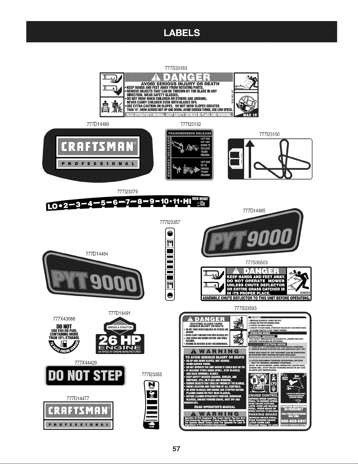
777D14480
777S33183
--i
'_
AVOID SERIOUS iNJURY OR DEATH
oKEEP HANDSAND FEETAWAY FROM ROTATINGPARTS. _, 14
• REMOVE OBJECTSTHAT CARBE THRQWHBY THE BLADEImANY _ -- 4
. mRECTJOH. WEN{ SAFETYOLAESES.
DOHOT MOW WHEH CRILOREHOR OTHERSARE AROOHD. _,
_,HEVEH CARRYCHJLDREHEVENWITH BLADESOFF. P, .......
USE EXTRA CAUTIONON SLOPES. DONOTMOW SLOPESGREATER
THAN15%MOWACR_ NOTUPANDDGWH.AVOIDSUDDE_TURHS,USELOWSPEED.
777123132
777123150
k
777123379
777D14484
777X43688
DONOT
USE E85 OR FUEL
CONTAINING MORE
o
THAN 10 YoETHANOL
W
777X44429
777D14491
777123357
777123355
777D14485
777S30503
ASSEMBLECHUTEDEFLECTORTO THIS UNIT BEFOREOPERATING.
777S33593
777D14477
57
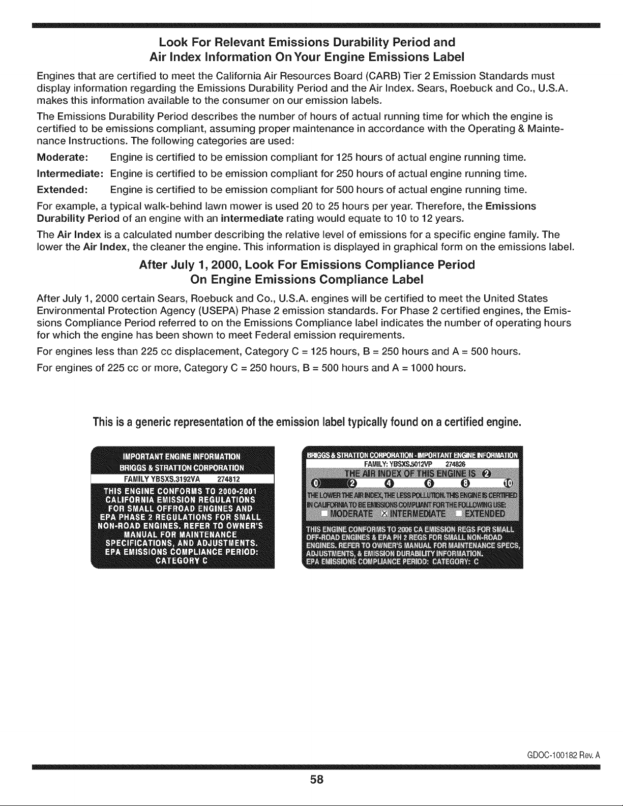
Look For Relevant Emissions Durability Period and
Air index information On Your Engine Emissions Label
Engines that are certified to meet the California Air Resources Board (CARB) Tier 2 Emission Standards must
display information regarding the Emissions Durability Period and the Air Index. Sears, Roebuck and Co., U.S.A.
makes this information available to the consumer on our emission labels.
The Emissions Durability Period describes the number of hours of actual running time for which the engine is
certified to be emissions compliant, assuming proper maintenance in accordance with the Operating & Mainte-
nance Instructions. The following categories are used:
Moderate: Engine is certified to be emission compliant for 125 hours of actual engine running time.
Intermediate: Engine is certified to be emission compliant for 250 hours of actual engine running time.
Extended: Engine is certified to be emission compliant for 500 hours of actual engine running time.
For example, a typical walk-behind lawn mower is used 20 to 25 hours per year. Therefore, the Emissions
Durability Period of an engine with an intermediate rating would equate to 10 to 12 years.
The Air Index is a calculated number describing the relative level of emissions for a specific engine family. The
lower the Air Index, the cleaner the engine. This information is displayed in graphical form on the emissions label.
After July 1,2000, Look For Emissions Compliance Period
On Engine Emissions Compliance Label
After July 1, 2000 certain Sears, Roebuck and Co., U.S.A. engines will be certified to meet the United States
Environmental Protection Agency (USEPA) Phase 2 emission standards. For Phase 2 certified engines, the Emis-
sions Compliance Period referred to on the Emissions Compliance label indicates the number of operating hours
for which the engine has been shown to meet Federal emission requirements.
For engines less than 225 cc displacement, Category C = 125 hours, B = 250 hours and A = 500 hours.
For engines of 225 cc or more, Category C = 250 hours, B = 500 hours and A = 1000 hours.
This is a generic representation of the emission label typically found on a certified engine.
FAMILYYSSXS.3192VA 274812
GDOC-100182Rev.A
58
(Thispageapplicablein the U.S.A.and Canadaonly.)
Sears, Roebuck and Co., U.S.A. (Sears), the California Air Resources Board (CARD)
and the United States Environmental Protection Agency (U.S. EPA)
Emission Control System Warranty Statement (Owner's Defect Warranty Rights and Obligations)
EMISSIONCONTROLWARRANTYCOVERAGEISAPPLICABLETO CERTI-
FIEDENGINESPURCHASEDIN CALIFORNIAIN 1995ANDTHEREAF-
TER,WHICHARE USEDINCALIFORNIA,ANDTO CERTIFIEDMODEL
California and United States Emission
The CaliforniaAir ResourcesBoard(CARD),U.S.EPAand Searsare pleased
to explainthe EmissionControlSystemWarrantyon your modelyear2000and
latersmalloff-roadengine(SORE).In California,newsmall off-roadengines
mustbe designed,builtand equippedto meetthe State'sstringentanti-smog
standards.Elsewherein the UnitedStates,newnon-road,spark-ignition
enginescertifiedfor modelyear 1997and latermustmeetsimilar standardsset
forth bythe U.S.EPA.Sears mustwarrantthe emissioncontrolsystemon your
YEAR 1997ANDLATERENGINESWHICHARE PURCHASEDANDUSED
ELSEWHEREIN THEUNITEDSTATES(ANDAFTERJANUARY1,2001 IN
CANADA).
Control Defects Warranty Statement
enginefor theperiodsoftime listedbelow,providedtherehas been noabuse,
neglector impropermaintenanceof your smalloff-roadengine.Youremis-
sion controlsystemincludespartssuch as thecarburetor,air cleaner,ignition
system,mufflerand catalyticconverter.Also includedmaybe connectorsand
otheremissionrelatedassemblies.Wherea warrantableconditionexists,Sears
will repairyour smalloff-roadengineat no costto you includingdiagnosis,parts
and labor.
Sears Emission Control Defects Warranty Coverage
Smalloff-roadenginesarewarrantedrelativeto emissioncontrolpartsdefects
fora periodof one year,subjectto provisionsset forth below.Ifany covered
Owner's Warranty
Asthe smalloff-roadengine owner,you are responsiblefor the performanceof
therequiredmaintenancelistedin yourOperatingand MaintenanceInstruc-
tions.Searsrecommendsthatyou retain allyourreceiptscoveringmaintenance
on yoursmalloff-roadengine,butSears cannotdenywarrantysolelyfor the
lackof receiptsor for yourfailureto ensurethe performanceof allscheduled
maintenance.As the smalloff-roadengineowner,you shouldhoweverbe
awarethat Searsmaydenyyou warrantycoverageif your smalloff-roadengine
ora part hasfailed dueto abuse,neglect,impropermaintenanceor unap-
parton yourengineis defective,the part will be repairedorreplacedbySears.
Responsibilities
provedmodifications.Youare responsiblefor presentingyour smalloff-road
engineto an AuthorizedSearsServiceDealeras soonas a problemexists.The
undisputedwarrantyrepairsshouldbe completedina reasonableamountof
time,not to exceed30 days.Ifyou haveany questionsregardingyourwarranty
rightsand responsibilities,you shouldcontacta SearsService Representative
at 1-800-469-4663.The emissionwarrantyis a defectswarranty.Defectsare
judgedon normalengineperformance.Thewarrantyis notrelatedto an in-use
emissiontest.
Sears Emission Control Defects Warranty Provisions
ThefollowingarespecificprovisionsrelativetoyourEmissionControlDefectsWarrantyCoverage.ItisinadditiontotheSearsenginewarrantyfornon-regulated
enginesfound in the Operatingand MaintenanceInstructions.
1. WarrantedParts
Coverageunderthis warrantyextendsonly to the parts listedbelow(the
emissioncontrolsystemsparts)to the extentthese partswere presenton
the engine purchased.
a. FuelMeteringSystem
• Cold start enrichmentsystem
• Carburetorand internalparts
• FuelPump
b. Air lnduction System
• Air cleaner
• Intakemanifold
c. IgnitionSystem
• Spark plug(s)
• Magnetoignitionsystem
d. CatalystSystem
• Catalyticconverter
• Exhaustmanifold
• Air injectionsystemor pulsevalve
e. MiscellaneousItemsUsedin AboveSystems
• Vacuum,temperature,position,time sensitivevalves
andswitches
• Connectorsandassemblies
2. Lengthof Coverage
Searswarrantsto the initialownerand eachsubsequentpurchaserthat
the WarrantedParts shallbe free from defects in materialsandworkman-
shipwhich causedthe failure of the WarrantedPartsfor a periodof one
yearfromthe datethe engineis deliveredto a retailpurchaser.
3. NoCharge
Repairor replacementof anyWarrantedPartwill be performedat no
chargeto the owner,includingdiagnosticlabor whichleadsto the
determinationthata WarrantedPartis defective,if the diagnosticwork is
performedat an AuthorizedSears ServiceDealer.Foremissionswarranty
servicecontact yournearestAuthorizedSearsServiceDealeras listed in
the "YellowPages"under"Engines,Gasoline,""GasolineEngines,""Lawn
Mowers,"or similarcategory.
4. Claimsand CoverageExclusions
Warrantyclaimsshall be filed in accordancewiththe provisionsof the
Sears EngineWarrantyPolicy.Warrantycoverageshall be excludedfor
failuresof WarrantedPartswhichare not original Sears partsor because
of abuse, neglector impropermaintenanceas setforth inthe Sears
EngineWarrantyPolicy.Sears is not liableto coverfailuresof Warranted
Partscausedby the use of add-on,non-original,or modifiedparts.
5. Maintenance
Any WarrantedPart whichis not scheduledfor replacementas required
maintenanceor whichis scheduledonly for regularinspectionto the effect
of "repairor replaceas necessary"shallbe warrantedasto defectsfor the
warrantyperiod.Any WarrantedPartwhich is scheduledfor replacement
as requiredmaintenanceshallbe warrantedasto defectsonly forthe
periodof time up to the firstscheduledreplacementfor that part.Any
replacementpart that is equivalentin performanceand durabilitymay
be usedin the performanceof any maintenanceor repairs.The owneris
responsibleforthe performanceof allrequiredmaintenance,as definedin
the SearsOperatingand MaintenanceInstructions.
6. ConsequentialCoverage
Coveragehereundershallextendto thefailure of any engine components
caused bythe failureof any WarrantedPartstill underwarranty.
Inthe USAandCanada,a 24 hour hot line, 1-800-469-4663,has a menu of pre-recordedmessagesofferingyou enginemaintenanceinformation.
GDOC-100188Rev.A
59
FEDERAL and/or CALIFORNIA EMISSION CONTROL WARRANTY STATEMENT
YOUR WARRANTY RIGHTS AND OBLIGATIONS
MTDConsumerGroupInc,the UnitedStatesEnvironmentalProtectionAgency (EPA),and, forthose productscertifiedfor sale in the stateof California,the
CaliforniaAir ResourcesBoard(CARB)are pleasedto explainthe emission(evaporativeand/or exhaust)controlsystem(ECS) warrantyon youroutdoor2006
andlater smalloff-roadspark-ignitedengine andequipment(outdoorequipmentengine)In California,new outdoorequipmentengines mustbe designed,built and
equippedto meetthe State'sstringentanti-smogstandards(in other states, 1997andlater modelyear equipmentmustbe designed,built,and equippedto meet
theU.S. EPAsmalloff-road, sparkignitionengine regulations.MTDConsumerGroupInc mustwarrantthe ECSon your outdoorequipmentenginefor the periodof
timelisted belowprovidedtherehas been no abuse,neglector impropermaintenanceof outdoorequipmentengine.
Your ECSmayincludeparts such as the carburetor,fuel-injectionsystem,the ignitionsystem,catalyticconverter,fuel tanks,fuel lines,fuelcaps,valves,canisters,
filters,vapor hoses,clamps,connectors,andotherassociatedemission-relatedcomponents.
Wherea warrantableconditionexists, MTDConsumerGroup Incwill repairyouroutdoorequipmentengine at no cost to you includingdiagnosis,parts and labor.
MAN UFACTURER'S WARRANTY COVERAGE:
Thisemissioncontrolsystemis warrantedfor two years. If any emission-relatedpart on your outdoorequipmentengineis defective,the part will be repairedor
replacedby MTDCONSUMERGROUPINC.
OWNER'S WARRANTY RESPONSIBILITIES:
Asthe outdoorequipmentengineowner,you are responsiblefor performanceof the requiredmaintenancelisted in your owner'smanual.MTDConsumerGroup
Inc recommendsthat you retain all receiptscoveringmaintenanceonyouroutdoorequipmentengine,butMTDConsumerGroupInc cannotdeny warrantysolely
forthe lackof receipts.
Asthe outdoorequipmentengineowner,you shouldhoweverbe awarethat MTDConsumerGroupInc may denyyou warrantycoverageif your outdoorequipment
engineor a part has failed due to abuse, neglect,or impropermaintenanceor unapprovedmodifications.
Youare responsiblefor presentingyouroutdoorequipmentengineto MTDConsumerGroupInc'sdistributioncenteror servicecenteras soon asthe problem
exists.The warrantyrepairsshouldbe completedin a reasonableamountof time, notto exceed30 days.If you havea questionregardingyour warrantycoverage,
you shouldcontactthe MTDConsumerGroupIncService Departmentat 1-800-800-7310orvia emailat http://support.mtdproducts.com
GENERAL EMISSIONS WARRANTY COVERAGE:
MTDConsumerGroupIncwarrantsto the ultimatepurchaserand eachsubsequentpurchaserthat theoutdoorequipmentengineis: Designed,built and equipped
so asto conformwithall applicableregulations;and freefromdefects in materialsand workmanshipthatcausethe failureof a warrantedpart to be identicalin all
materialrespectsto that part as describedin MTDConsumerGroup Inc'sapplicationfor certification.
The warrantyperiodbeginson thedate the outdoorequipmentengine is deliveredto an ultimate purchaserorfirst placedintoservice.The warrantyperiodis two
years.
Subjectto certain conditionsand exclusionsasstated below,the warrantyon emission-relatedparts is asfollows:
1. Any warrantedpart that is not scheduledfor replacementas requiredmaintenancein the written instructionssupplied,is warrantedforthe warrantyperiod
statedabove. Ifthe part fails duringthe periodof warrantycoverage,thepart will be repairedor replacedbyMTDConsumerGroupInc accordingto subsection
(4) below.Anysuch part repairedor replacedunderwarrantywillbe warrantedfor the remainderof the period.
2. Any warrantedpart that is scheduledonly for regularinspectionin the writteninstructionssupplied is warrantedforthe warrantyperiodstatedabove.Anysuch
part repairedor replacedunderwarrantywill be warrantedforthe remainingwarrantyperiod.
3. Any warrantedpart that is scheduledfor replacementas requiredmaintenancein thewritten instructionssuppliedis warrantedfor the periodof time beforethe
first scheduledreplacementdatefor that part. If the partfails beforethefirst scheduledreplacement,the part will be repairedor replacedby MTDConsumer
GroupInc accordingto subsection(4) below.Any such part repairedor replacedunderwarrantywill bewarrantedfor the remainderof the periodprior to the
first scheduledreplacementpointfor the part.
4. Repairor replacementof any warrantedpart underthe warrantyprovisionshereinmustbe performedat a warrantystationat no chargeto the owner.
5. Notwithstandingthe provisionsherein,warrantyservicesor repairswill beprovidedat all of our distributioncentersthatare franchisedto servicethe subject
enginesor equipment.
6. The outdoorequipmentengine ownerwill not be chargedfor diagnostic laborthat is directlyassociatedwithdiagnosisof a defective,emission-relatedwar-
rantedpart, providedthat suchdiagnosticworkis performedat a warrantystation.
7. MTDConsumerGroupInc is liablefor damagesto otherengineor equipmentcomponentsproximatelycausedby a failure underwarrantyof any warranted
part.
8. Throughoutthe off-roadengineand equipmentwarrantyperiodstatedabove, MTDConsumerGroupInc will maintaina supply of warrantedparts sufficientto
meetthe expecteddemandfor such parts.
9. Any replacementpart maybe usedin the performanceof any warrantymaintenanceor repairsand mustbe providedwithoutchargeto the owner.Suchuse will
notreducethe warrantyobligationsof MTDConsumerGroupInc.
10.Add-onor modifiedpartsthat are not exemptedbythe Air ResourcesBoardmay not be used.The use of any non-exemptedadd-on or modifiedparts by the
ultimatepurchaserwill be groundsfor disallowinga warrantyclaims. MTDConsumerGroup Incwill notbe liableto warrantfailuresof warrantedparts caused
bythe use of a non-exemptedadd-onor modifiedpart.
WARRANTED PARTS:
The repairor replacementof any warrantedpart otherwiseeligiblefor warrantycoveragemay be excludedfrom such warrantycoverageif MTDConsumerGroup
Inc demonstratesthatthe outdoorequipmentenginehas beenabused,neglected,orimproperlymaintained,and thatsuch abuse, neglect,or impropermainte-
nancewasthe direct causeof the needfor repairor replacementof the part.That notwithstanding,any adjustmentof a componentthat hasa factory installed,
andproperlyoperating,adjustmentlimitingdevice is still eligible for warrantycoverage.Further,the coverageunderthis warrantyextendsonly to partsthat were
presentonthe off-roadengineand equipmentpurchased.
Thefollowing emissionwarrantypartsare covered(if applicable):
(1) FuelMeteringSystem
• Cold start enrichmentsystem(softchoke)
• Carburetorand internalparts (or fuel injectionsystem)
• Fuelpump
• Fueltank
(2) Air InductionSystem
• Air cleaner
• Intakemanifold
(3) IgnitionSystem
• Spark plug(s)
• Magnetoignitionsystem
(4) ExhaustSystem
• Catalyticconverter
• SAI (Reed valve)
(5) MiscellaneousItemsUsedin AboveSystem
• Vacuum,temperature,position,time sensitivevalvesand switches
• Connectorsandassemblies
(6) EvaporativeControl
• Fuelhose
• Fuelhoseclamps
• Tetheredfuel cap
• Carboncanister
• Vapor lines
GDOC-100223Rev.A
Declaracion de garantia .................................................. 62
Instrucciones sobre seguridad ....................................... 63
Montaje ........................................................................... 70
Conozca su cortadora de cesped .................................. 73
Funcionamiento ............................................................... 76
Servicio y Mantenimiento ............................................... 79
Almacenamiento fuera de temporada ............................ 90
Soluci6n de Problemas ................................................... 91
Lista de piezas ................................................................ 34
NL_merosde servicio ......................................... Contratapa
GARANTiA TOTAL PROFESIONAL CRAFTSMAN
En condicionesnormalesde operaci6ny mantenimientoseg_n lasinstruccionessuministradas,si alguna pieza no descartablede esteequipo montanefallara
debidoa defectosde materialo de manode obradentrode los dosaSosde lafecha de compra, Ilameal 1-800-659-5917paraacordar unavisitade reparaci6n
a domiciliosin cargo.
El bastidory el eje delanteroserAnreparadossincargo durantecinco a_os a partirde lafecha de comprasi tienen defectosde materialo de mano de obra.
Todala coberturade garanfiaanteriors61oserAvalidadduranteuna5o a partirde lafecha de comprasi el equipomontane se utiliza en algOnmomentopara
fines comercialeso de alquiler.
En todoslos casos, si es imposiblerepararlo,el equiposerAreemplazadosin cargo por otro del mismomodeloo su equivalente.
La bateriaserAreemplazadasin cargo durante90 dias a partirde lafecha de comprasi tienedefectosde materialo de mano de obra (nuestraspruebas
demuestranqueno mantienela carga).
Esta garanfiacubreONICAMENTElos defectosen losmaterialesyen la manode obra. Sears NO pagarApor:
• Elementosconsumiblesque sedesgastanpor el usonormal,incluyendoentreotros, lascuchillas, buj[as,depuradoresde aire,correas, y filtrosde aceite.
• Serviciosde mantenimientoestAndar,cambiosde aceiteo afinaci6n.
• Cambiode neumAticoso reparacionespor pinchadurascon objetosexternoscomoclavos, espinas,toconeso vidrios.
• Reemplazoo reparaci6nde neumAticoso ruedascomo resultadodel desgastenormal,unaccidente,o funcionamientoo mantenimientoincorrectos.
• Reparacionesnecesariasdebidoal abuso del operador,incluyendoentre otros,el da_o ocasionadopot remolcarobjetosmAsalia de la capacidaddel
equipomontane,el impacto contraobjetosquetuerzanla estructurao el cigQe6al,o pot acelerardemasiadoel motor.
• Reparacionesnecesariasdebidoa negligenciadel operador,incluyendoentreotras,losda_os mecAnicosy electricoscausadosporel almacenamiento
incorrecto,el uso de aceitede gradoincorrectoy/o en cantidadesno adecuadas,pot nomantenerel Areade cubierta librede residuosinflamables,o pot
no mantenerel equipode acuerdo con las instruccionescontenidasen el manualdel propietario.
• Limpiezao reparacionesdel motor(sistemade combustible)debidas a combustibleque se determinaestAcontaminadou oxidado(viejo). En general,el
combustibledebe utilizarseen un periodonomayorde 30 dias a partirde su adquisici6n.
• Eldeterioroy desgastenormalde losacabadosexteriores,o reemplazode laetiquetadel producto.
Estagaranfia seaplica solamentemientrasel productose encuentredentro de los EstadosUnidos.
Estagaranfia leotorga derechoslegalesespecificos,pero usted podriagozarde otrosderechosen raz6nde su lugar de residencia.
Sears, Roebuck and Co., Hoffman Estates, IL 60179
HPtotal: 26
Aceitedel motor: SAE30
Combustible: UnleadedGasoline
Bujias: Champion®RC12YC
Motor: Briggs& Stratton ProfessionalSeries
N_mero de modelo
N_mero de serie
Fechade compra
Registrearriba el nOmerode modelo,el
nOmerode seriey la fechade compra.
© SearsBrands,LLC 62
Lapresenciadeeste sirnboloindicaque setrata de instrucciones
irnportantesde seguridadquese debenrespetarpara evitar
poneren peligrosu seguridadpersonaly/o materialy lade otras
personas.Leay siga todaslas instruccionesde estemanualantes
de poneren funcionarnientoestarn_.quina.Si no respetaestas
instruccionespodriaprovocarlesionespersonales.Cuandoveaeste
sirnbolo,ipresteatenci6na la advertencia!
PROPOSICION 65 DE CALIFORNIA
Elescapedel motorde esteproducto,algunosde suscornponentes
y algunoscornponentesdelvehiculocontieneno liberan sustancias
quirnicasqueel estadode Californiaconsideraque puedenproducir
c_.ncer,defectosde nacirnientouotrosproblernasreproductivos.
Losbornesdela bateriay los accesoriosdines contienenplornoy
cornpuestosde plorno,sustanciasquirnicasque seg_nIo estableci-
do pot el Estadode Californiacausanc_.ncery da_osenel sisterna
reproductivo.Ldveselas manos despu_sde estar en contacto
con estoscomponentes.
Estarn_.quinarueconstruidaparaseroperadade acuerdocon
las reglasde seguridadcontenidaseneste manual.AI igualque
concualquiertipo deequipo rnotorizado,un descuidoo errorpor
partedeloperadorpuedeproducirlesionesgraves.Estarn_.quina
es capazde arnputarrnanosy piesy dearrojarobjetoscon gran
fuerza.Deno respetarlas instruccionesde seguridadsiguientesse
puedenproducirlesionesgraveso la rnuerte.
Su responsabilidad--Restrinja el usode esta rn_.quina
rnotorizadaalas personasque lean,cornprendany respetenlas
advertenciase instruccionesqueaparecenen este manualyen la
rn_.quina.
iGI.IARI)E ESTASINSTRUCCIONES!
FUNCIONAIVIIENTO GENERAL
• Lea,entienday curnplatodaslas instruccionesincluidasen
la rn_.quinayen los rnanualesantes dernontarlay utilizarla.
Guardeestemanualenun lugarseguroparaconsultasfuturasy
peri6dicas,asi cornoparasolicitarrepuestos.
• Farniliaricesecontodoslos controlesy con el usoadecuado
delos rnisrnos.Sepac6rnodetenerla rn_.quinay desactivarlos
controlesr_.pidarnente.
• No perrnitanuncaque los ni_osrnenoresde 14a_osutilicen
estarn_.quina.Los ni_osde 14a_osen adelantedeben leery
entenderlas instruccionesde operaci6ny norrnasde seguridad
contenidaseneste manual,yen la rn_.quinay debenser
entrenadosy supervisadospor un adulto.
• Nuncaperrnitaquelos adultosoperenesta rn_.quinasin recibir
antesla instrucci6napropiada.
• Paraayudaraevitar el contactocon las cuchillaso unalesi6npor
algQnobjetoquesea arrojado,rnantengaa los observadores,a
los ayudantes,ni_osy rnascotasalejadosal rnenos25 metrosde
la rn_.quinarnientrasest,. en funcionarniento.Detengala rn_.quina
si alguienentraen lazona.
• Inspeccionerninuciosarnenteel Areadondeutilizar_,el equipo.
Retiretodaslas piedras,palos,cables,huesos,juguetesy otros
objetosextra_osquepodrianser recogidosy arrojadospor la
acci6nde las cuchillas.Losobjetosarrojadospor larn_.quina
puedenproducirlesionesgraves.
• Planifiqueel patr6ndecorte delc_spedque ha de seguirpara
evitarla descargade materialhacialoscarninos,las veredas,los
observadores,etc.Eviteadern_.sdescargarmaterialcontralas
paredesy obstruccionesquepodrianprovocarque el material
descargadorebotecontrael operador.
• Paraprotegerselos ojos utilicesiernpreanteojoso antiparras
deseguridadrnientrasoperala rn_.quinao rnientraslaajusta
o repara.Losobjetosarrojadosque rebotanpuedenproducir
lesionesocularesgraves.
• Utilicezapatosde trabajoresistentes,desuelafuerte,asi corno
pantalonesy carnisasajustados.Las prendassueltaso las
alhajaspuedenquedaratrapadasen las piezasrnovibles.Nunca
operela rn_.quinadescalzoo con sandalias.
• Est_atentoa la cortadoray a la direcci6nde la descargade
losaditarnentosy noapuntea nadie.Nuncaopere lacortadora
de c_spedsin queest_nen su lugarapropiadolacubiertade
descargao elcolectorde recortesde cesped.
• Nopongalasrnanoso lospies cercade las piezasrotatoriaso
debajode la plataforrnadecorte. El contactocon las cuchillas
puedeproducirla arnputaci6nde rnanosy pies.
• Unacubiertade descargafaltanteo da_adapuedeprovocarel
contactocon lacuchillao lesionespot objetosarrojados.
• Detengala(s)cuchilla(s)cuandoatraviesesenderos,sendaso
carninosde gravay cuandonoest_cortandoel cesped.
• Vigileel tr_.nsitovehicularcuandoest_operandocercade o en
crucesde carninos.Estarn_.quinanodebeutilizarseen lavia
pQblica.
• Noopereestarn_.quinabajolosefectosdelalcoholode drogas.
• Corteel cespedsolarnentecon luzde diao conunabuenaluz
artificial.
• Nuncatransportepasajeros.
• Desenganchela(s)cuchilla(s)antesde colocarlarnarchaatr_.s.
Retrocedalentarnente.Siernpremirehaciaabajoy haciaatr_.santes
y rnientrasretrocede,paraevitaraccidentes.
• Reduzcala velocidadantesdedar lavuelta.Operelarn_.quina
suavernente.Evitelaoperaci6nerr_.ticay la velocidadexcesiva.
• Desenganchela(s)cuchilla(s),coloqueelfrenode estaciona-
rniento,detengaelmotory esperehastaque la(s)cuchilla(s)se
detenga(n)porcornpletoantesderetirarelcolectordec_sped,
vaciarlos recortes,destaparel canal,retirarrestosde cespedo
desechos,o hacercualquierajuste.
63
• Nuncadeje larn_.quinaen funcionarnientosinvigilancia.Apague
siernprelascuchillas,coloqueelfrenodernano,detengaelmotory
retirela Ilaveantesde bajarsedelvehiculo.
• Tengasurnocuidadoalcargaro descargarlarn_.quinaen un
rernolqueocarni6n.Estaunidadnodebeconducirseen ascensoo
descensoderarnpas,porquepodrialadearsey provocarlesiones
personalesgraves.Enlas rarnpaslarn_.quinasedebe ernpujar
rnanualrnenteparacargarlao descargarlacorrectarnente.
• Elsilenciadory el motorse calientany puedencausarquernaduras.
Nolos toque.
• Reviseel espaciolibrepot encirnade la cabezaantesde conducir
bajolas rarnasbajasde _.rboles,cables,cerrarnientosde puertas,
etc.enloscualesel operadorpodriaatorarseo serernpujadofuera
dela rn_.quina,Ioquepodriaresultaren lesionesgraves.
• Desenganchetodoslosernbraguesdelos accesoriosy presione
totalrnenteel pedaldelfrenoantesdeintentararrancarel motor.
• Larn_.quinaest,.diseSadaparacortarc_spedresidencialnormal,
conunaalturano mayora 10".Nointentecortarcespeddernasiado
crecido,seco(porej., pastura)nipilasde hojassecas.Elc_sped
y las hojassecaspuedenentrarencontactoconel escapedel
motory/o acurnularseen la plataforrnade la cortadorade cesped,
convirti_ndoseen un peligrode incendio
• Utilicesolarnenteaccesoriosy aditarnentosaprobadosparaesta
rn_.quinapot el fabricantedelarnisrna.Lea,cornprenday siga
todaslasinstruccionesproporcionadasconlosaccesorioso
aditarnentosaprobados.Paraobtenerunalistadelosaccesorios
aprobadosy losarchivosadjuntos,Ilarne1-800-659-5917.
• Losdatosestadsticosrnuestranquelosoperadoresde 60 aSos
y rnayoresseven involucradosenunaltoporcentajedelesiones
relacionadascontractorescorta cesped.Estosoperadoresdeben
evaluarsu capacidadparaoperarel tractorcortac_spedenforrna
suficienternentesegurapara protegersea ellosrnisrnosy a los
dern_.scontralesionesgraves.
Si se presentansituacionesqueno est_.nprevistasen este
manualsea cuidadosoy use el sentidocornQn.Contacto1-800-
659-5917parainforrnaci6ny asistencia.
FUNCIONAiVIIENTO EN PENDIENTES
Las pendientesson unfactorirnportanterelacionadoconaccidentes
porderrapey vuelcosquepuedenproducirlesionesgravese incluso
la rnuerte.La operaci6nen pendientesrequieremayorprecauci6n.
Si nopuede retrocederen la pendienteo si no se sienteseguro,no
realiceningunaoperaci6nde corte.
Parasu seguridad,use el indicadordependientesque se incluye
cornopartede estemanualpararnedirla pendienteantesde operarla
rn_.quinaenunazonainclinada.Sila pendientees mayorde 15grados
segQnel rnedidor,no opereestarn_.quinaenese sector,puespodria
causarlesionesgraves.
HagaIo siguiente:
• Podehaciaarribay abajodelas pendientes,nodeforrnatrans-
versal.Tengacuidadocuandocarnbiededirecci6nal operaren
pendiente.
• Est_atentoa loshoyos,surcos,baches,rocas,uotrosobjetos
ocultos.El terrenodesniveladopuedevoltearla rn_.quina.Elcesped
altopuedeocultarobst_.culos.
Vayaa bajavelocidad.ElijaunavelocidadIosuficienternentebaja,
de rnodoque notengaquedetenerseohacercarnbiosrnientras
est,.sobrela pendiente.Losneurn_.ticospodrianperdertracci6n
sobrelaspendientesaQncuandolosfrenosfuncionaranapro-
piadarnente.Siernprernantengalarn_.quinaen carnbiornientras
desciendelaspendientes,parapoderfrenarconel motor.
• Sigalas recornendacionesdel fabricanteparalos pesoso contra-
pesosdelas ruedas,pararnejorarla estabilidaddelarn_.quina.
Pararecornendaciones,Ilarneal 1-800-659-5917.
• Tengaespecialcuidadocon loscolectoresdecespeduotros
aditarnentos.Losrnisrnospuedenrnodificarlaestabilidaddela
rn_.quina.
• Hagaquetodoslos rnovirnientosen laspendientesseanlentosy
graduales.Nocarnbierepentinarnentelavelocidadni la direcci6n.
Unfrenadoo carnbiodevelocidadrepentinospuedencausarque
el frentede la rn_.quinase levantey d_unavolteretahaciaatr_.s,Io
quepodriaproducirlesionesgraves.
• Evitearrancaro detenerseenunapendiente.Silosneurn_.ticos
pierdenlatracci6n,desenganchelascuchillasy descienda
lentarnentela pendiente.
No hagaIo siguiente:
• Nogire sobrelas pendientesarnenosqueseanecesario.Sies
posible,girelentarnentey gradualrnenteduranteel descenso.
• Nocorteel c_spedcercade pozos,hundirnientosoterraplenes.La
cortadoradec_spedpuedevolcarserepentinarnentesiunade las
ruedasest,.sobreelhordede unacantilado,zanjao siunhordese
desrnorona.
• Nointenteestabilizarlarn_.quinaponiendoelpieenel suelo.
• Noutiliceuncolectordecespeden pendientesernpinadas.
• Nopodeelcespedh_rnedo.Unarnenortracci6npodriacausar
derrapes.
• Noparadescender.Elexcesode velocidadpuedehacerqueel
operadorpierdaelcontroldela rn_.quina,ocasionandolesiones
gravese inclusolarnuerte.
• Norernolquecargaspesadasdetr_.sdelosaditarnentos(carritode
basuracargado,podadorade rodillos,etc)en pendientesrnayores
de5 grados.Cuandosedesplazapendienteabajo,el pesoadicional
tiendeaernpujareltractory puedehacerquese pierdaelcontrol
delrnisrno(porejernplo,eltractorsepuedeacelerar,se reducela
capacidadparafrenary rnaniobrar,losaccesoriospuedenplegarse
cornouncortaplurnasy hacerqueeltractorvuelque).
NINOS
Puedenocurriraccidentestr_.gicossi el operadorno est,.atentoa la
presenciade niSos.PotIo general,los niSosse sientenatraidospor
estetipo de rn_.quinasy su funcionarniento.Noentiendenlos riesgos
ni los peligros.Nuncaasurnaquelos niSosperrnanecer_.nen el rnisrno
lugardonde losvio pot Qltirnavez.
• Mantengaa losniSosfueradel_.readetrabajoy bajoestricta
vigilanciadeunadultoresponsableadern_.sdelpropiooperador.
Est_alertay apaguela rn_.quinasiunniSoingresaal _.rea.
• Antesy rnientrasest,.retrocediendo,mirehaciaatr_.sy cuidequeno
hayaniSos.
NuncatransporteniSos,aQnconla cuchillaapagada.Podriancaerse
y resultarseverarnenteheridoso interferirconlaoperaci6nsegurade
la rn_.quina.
Tengaextrernaprecauci6ncuandoseaproxirneaesquinasciegas,
portales,arbustos,_.rbolesuotrosobjetosquepuedanirnpedirlever
a unniSoquesecruceenel recorridode larn_.quina.
64
• Paraevitaraccidentesaloperaren rnarchaatr_.s,siernpredesengan-
chelascuchillasantesdecolocarrnarchaatr_.s.Siest,.instalado,
el"ModoPrecaucidnMarchaAtr_.s"(hojasdeoperarlarn_.quina,
rnientrasquelospaseosa la inversa)nodebeutilizarsecuandohay
ni_osuotraspersonaspresentes.
• Mantengaa losni_osalejadosdelosrnotoresenrnarchao calientes.
Puedensufrirquernadurasconun silenciadorcaliente.
• Retirela Ilavecuandodejela rn_.quinasinvigilancia,evitequeuna
personasinautorizaci6nlarnaneje.
No perrnitanuncaque los ni_osrnenoresde 14a_osutilicenesta
rn_.quina.Losni_osde 14a_osen adelantedebenleery entenderlas
instruccionesdeoperaci6ny norrnasde seguridadcontenidaseneste
manual,yen la rn_.quinay debenserentrenadosy supervisadospor
unadulto.
REIVIOLQUE
• Rernolque_nicarnenteconunarn_.quinaquecuenteconun
enganchediseSadopararernolcar.Noacopleequiporernolcado
exceptoenelpuntodeenganche.
• SigalasrecornendacionesdelfabricanteenIoquerespectaalos
lirnitesdepesodelosequiposa rernolcary al rernolqueenpendien-
tes.Pararecornendaciones,Ilarneal 1-800-659-5917.
• Nuncaperrnitala presenciade niSosuotraspersonasdentroosobre
losequiposrernolcados.
• Enlaspendientes,el pesodelequiporernolcadopuedecausar
p_rdidadetraccidny perdidadecontrolde la rn_.quina.
• Siernpreuseextralaprecauci6nrernolcandoconunarn_.quina
capazde hacervueltasapretadas(p.ejpaseo"devueltacero"-en el
cortacesped).Hagaarnpliasvueltasparaevitaral gato-knifing.
• Despl_.ceselentarnentey dejedistanciaadicionalparafrenado.
• Noparadescender.
SERVIClO
Manejo seguro de la gasolina
Paraevitarlesionespersonaleso daSosrnaterialessea surnarnente
cuidadosoal rnanipularla gasolina.Lagasolinaes surnarnente
infiarnabley sus vaporespuedencausarexplosiones.Se puede
lesionargravernentesi derrarnagasolinasobreustedo sobrela ropa,
ya que_stase puedeincendiar. L_.vesela piely c_.rnbiesede ropade
inrnediato.
• Utilices61olos recipientesparagasolinaautorizados.
• NuncaIlenelos recipientesenel interiorde unvehiculoo carnidn
o cajade rernolquecon recubrirnientopl_.stico.Coloquesiernpre
los recipientesen el piso y lejosdel vehiculoantes de realizarla
carga.
• Cuandoseafactible,retireel equipoa gasolinadel carni6no
rernolquey II_neloen elsuelo. Siesto noes posible,Ileneel
equipoen unrernolqueconun contenedorport_.til,envezde
hacerlocon unaboquilladispensadoradegasolina.
• Mantengala boquillade Ilenadoencontactoconel horde del
dep6sitode combustibleo con la aberturadel recipienteen todo
rnornento,hastaterrninarlacarga.No utiliceundispositivode
boquilladeapertura/cierre.
• Apaguetodosloscigarrillos,cigarros,pipasy otrasfuentesde
cornbustidn.
• Nuncacarguecombustibleen la rn_.quinaenun espaciocerrado.
• Nuncasaquela tapadel combustibleniagreguecombustible
rnientrasel motorest,. calienteo enrnarcha.Dejequeel motor
seenfrie porIornenosdos rninutosantesde volvera cargar
combustible.
• NuncaIleneen excesoel dep6sitode combustible.Lleneel
tanquenorn_.sde 1/2pulgadapordebajode la basedel cuello
del tap6ndecarga, paradejarespaciopara laexpansi6ndel
combustible.
• Vuelvaa colocarlatapa dela gasolinay ajQstelabien.
• Lirnpieel combustiblequese hayaderrarnadosobreel motory el
equipo.Trasladela rn_.quinaa otrazona.Espere5 rninutosantes
de encenderelmotor.
• Parareducirel riesgode incendio,rnantengala rn_.quinalirnpia
de pasto,hojasy deacurnulacidndeotros residuos.Lirnpielos
derrarnesdeaceiteo combustibley saquetodos los residuos
ernbebidosde combustible.
• Nuncaguardela rn_.quinao el recipientede combustibleen un
espaciocerradodondehayafuego,chispaso luz piloto,corno
porejernplodecalentadoresde agua,calefactoresde arnbientes,
hornos,secadoresde ropau otrosaparatosa gas.
• Dejequelarn_.quinase enfriecinco rninutospor Iornenosantes
de guardarla.
Servicio general
• Nuncaenciendael motoren espacioscerradosoen unazona
con pocaventilacidn.Elescapedel motorcontienernondxidode
carbono,ungas inodoroy letal.
• Antesde lirnpiar,repararo inspeccionarla rn_.quina,cornpruebe
que la(s)cuchilla(s)y todaslas partesenrnovirnientose hayan
detenido.Desconecteel cablede la bujfay p6ngalohaciendo
rnasacontrael motorparaevitarquese enciendaaccidental-
rnente.
• Reviseperi6dicarnenteparaasegurarsequelas cuchillasse
detenganporcornpletoenaproxirnadarnentecinco(5) segundos
despu_sdeaccionarel controlde desenganchede la(s)
cuchilla(s).Si las cuchillasnose detienendentrodeeste lapso
de tiernpo,su unidaddeber_,ser reparadaporsu distribuidorde
servicioautorizadoMTD.
• Reviseconfrecuenciael funcionarnientodelsisternadefrenos
ya queest,.sujetoa desgasteporla operaci6nnormal.Ajustey
efectQernantenirnientosegQnse requiera.
65
• Reviselos pernosdemontajede la(s) cuchilla(s)y del motora
intervalosfrecuentesparaverificarqueest_nbien apretados.
Adem_.s,inspeccionevisualmentela(s) cuchilla(s)en buscade
daSos(porejemplo,desgasteexcesivo,abolladuras,rajaduras,
etc.). Reemplacela(s)cuchilla(s)Qnicamentecon lascuchillas
defabricantesde equiposoriginales(O.E.M.)listadasen este
manual.Elusode piezasque nocumplencon las especifi-
cacionesdelequipooriginalpodriatenercomoresultadoun
rendimientoincorrectoy adem_.sponeren riesgola seguridad.
• Lascuchillasdelas podadorassonmuyafiladas.Envuelvala
cuchillao utiliceguantesy extremelasprecaucionescuando
efectQemantenimiento.
Mantengatodoslos pernos,tuercasy tornillosbienajustados
paraasegurarsede que la m_.quinase encuentraen condiciones
segurasde operaci6n.
• Nuncaaltereel sistemade enclavamientode seguridadni
otrosmecanismosde seguridad.Controleperi6dicamenteque
funcionencorrectamente.
Despu_sdegolpearcon algQnobjetoextraSo,detengael motor,
desconecteel cablede la bujfay conecteel motora masa.
Inspeccioneminuciosamentela m_.quinaparaver si est,.daSada.
Repareel daSoantes dearrancary ufilizarla m_.quina.
Nuncatratede hacerajusteso reparacionesa lam&quina
mientrasel motorest&enmarcha.
• Loscomponentesdel colectorde c_spedy la cubiertade
descarga,estansujetosa desgastey daSosque podriandejar
expuestaspartesen movimientoo permifirque searrojenobjetos.
Paraprotegersuseguridad,verifiquefrecuentementetodoslos
componentesy reempl_.celosinmediatamentes61ocon piezasde
los fabricantesdel equipooriginal,listadosen este manual.Eluso
de piezasque no cumplencon las especificacionesdel equipo
originalpodriatenercomoresultadoun rendimientoincorrectoy
adem_.sponeren riesgola seguridad.
• Nocambiela configuraci6ndel reguladordel motorni Ioopere
a sobrevelocidad.El reguladordel motorcontrolala velocidad
m_.ximaseguradefuncionamientodel motor.
• Mantengao reemplacelasefiquetasde seguridade instrucciones
segQnseanecesario.
Respetelas normasreferentesa la disposici6ncorrectay las
reglamentacionessobregasolina,aceite,etc. para protegerel
medicambiente.
• SegQnla Comisi6nde Seguridadde Productosparael Consu-
midorde los EstadosUnidos(CPSC)y laAgenciade Protecci6n
Ambientalde los EstadosUnidos(EPA),esteproductotieneuna
vida Qtilmediade siete(7) aSos,6 270horasde funcionamiento.
AIfinalizarla vida0til media,adquieraunam_.quinanuevao haga
inspeccionaranualmente_staSearsporunou otrodistribuidorde
serviciosparacerciorarsedeque todoslos sistemasmec_.nicos
y de seguridadfuncionancorrectamentey no tienenexcesivo
desgaste.Si no Io hace,puedenproducirseaccidentes,lesiones
o muerte.
NO MODIFIQUE EL MOTOR
Paraevitarlesionesgraveso lamuerte,no modifiqueel motorbajo
ningunacircunstancia.Si cambiala configuraci6ndel reguladordel
motorel motorpuededescontrolarsey operara velocidadesinsegu-
ras.Nuncacambie laconfiguraci6nde f_.bricadel reguladordel motor.
AVlSO REFERIDO A EMISIONES
Losmotoresqueest_.ncertificadosy cumplencon las regulaciones
de emisionesfederalesEPAy de CaliforniaparaSORE(Equipos
peque_ostodoterreno)est_.ncertificadosparaoperarcongasolina
comQnsin plomoy puedenincluirlos siguientessistemasde control
de emisiones:Modificaci6nde motor(EM) y catalizadorde tresvias
(TWO)siest_.nequipadosde esa manera.
GUARDACHISPAS
EstamAquinaest,.equipadacon unmotorde combusti6ninternay
nodebe ser utilizadaen o cercade unterrenoagrestecubiertopor
bosque,malezaso hierbaexceptosi el sistemade escapedelmotor
est,.equipadocon un amortiguadordechispasquecumplacon las
leyeslocaleso estatalescorrespondientes,encaso de haberlas.
Si se utilizaunamortiguadorde chispasel operadorIo debemantener
en condicionesde usoadecuadas.Enel Estadode Californialas
medidasanteriormentemencionadassonexigidasporIcy (Arficulo
4442del C6digode RecursosPOblicosde California).Esposible
queexistanleyessimilaresen otrosestados.Lasleyesfederalesse
aplicanenterritoriosfederales.
Puedeconseguirel amortiguadordechispasparael silenciadora
travesdesu distribuidorautorizadode motoreso poni_ndoseen
contactoconel centrode servicioSears.
66
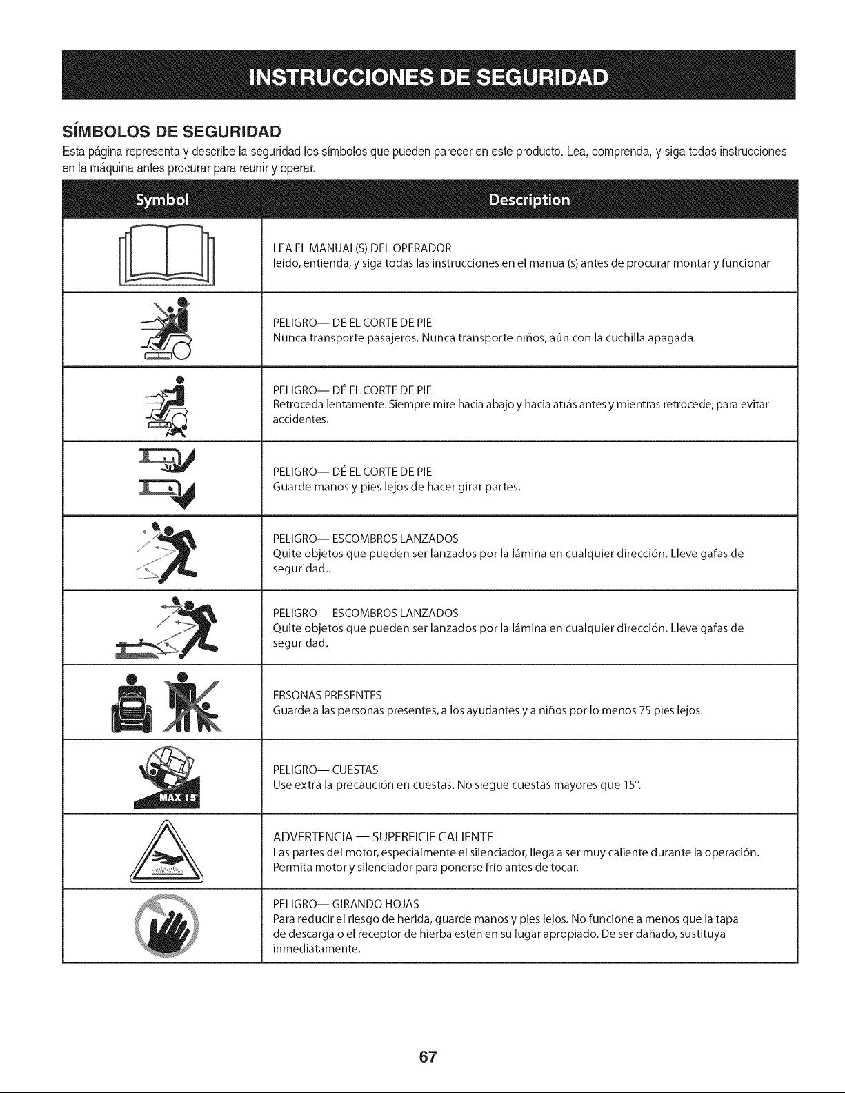
SilVlBOLOS DE SEGURIDAD
Estap&ginarepresentay describelaseguridadlos simbolosque puedenpareceren esteproducto.Lea,comprenda,y sigatodasinstrucciones
enla m_quinaantesprocurarparareuniry operar.
0
J
AL
LEA EL MANUAL(S) DEL OPERADOR
leido, entienda, y siga todas las instrucciones en el manual(s) antes de procurar montar y funcionar
PELIGRO-- DE EL CORTE DE PIE
Nunca transporte pasajeros. Nunca transporte ni_os, aun con la cuchilla apagada.
PELIGRO-- DE EL CORTE DE PIE
Retroceda lentamente. Siempre mire hacia abajo y hacia atr_is antes y mientras retrocede, para evitar
accidentes.
PELIGRO-- DE EL CORTE DE PIE
Guarde manos y pies lejos de hacer girar partes.
PELIGRO-- ESCOMBROS LANZADOS
Quite objetos que pueden ser lanzados por la I_imina en cualquier direcci6n. Lleve gafas de
seguridad..
PELIGRO-- ESCOMBROS LANZADOS
Quite objetos que pueden ser lanzados por la I_imina en cualquier direcci6n. Lleve gafas de
seguridad.
ERSONAS PRESENTES
Guarde alas personas presentes, a los ayudantes y a ni_os por Io menos 75 pies lejos.
PELIGRO-- CUESTAS
Use extra la precauci6n en cuestas. No siegue cuestas mayores que 15°.
ADVERTENCIA-- SUPERFICIECALIENTE
Las partes del motor, especialmente el silenciador, Ilega a set muy caliente durante la operaci6n.
Permita motor y silenciador para ponerse frio antes de tocar.
PELIGRO-- GIRANDO HOJAS
Para reducir el riesgo de herida, guarde manos y pies lejos. No funcione a menos que la tapa
de descarga o el receptor de hierba est_n en su lugar apropiado. De ser dahado, sustituya
inmediatamente.
67
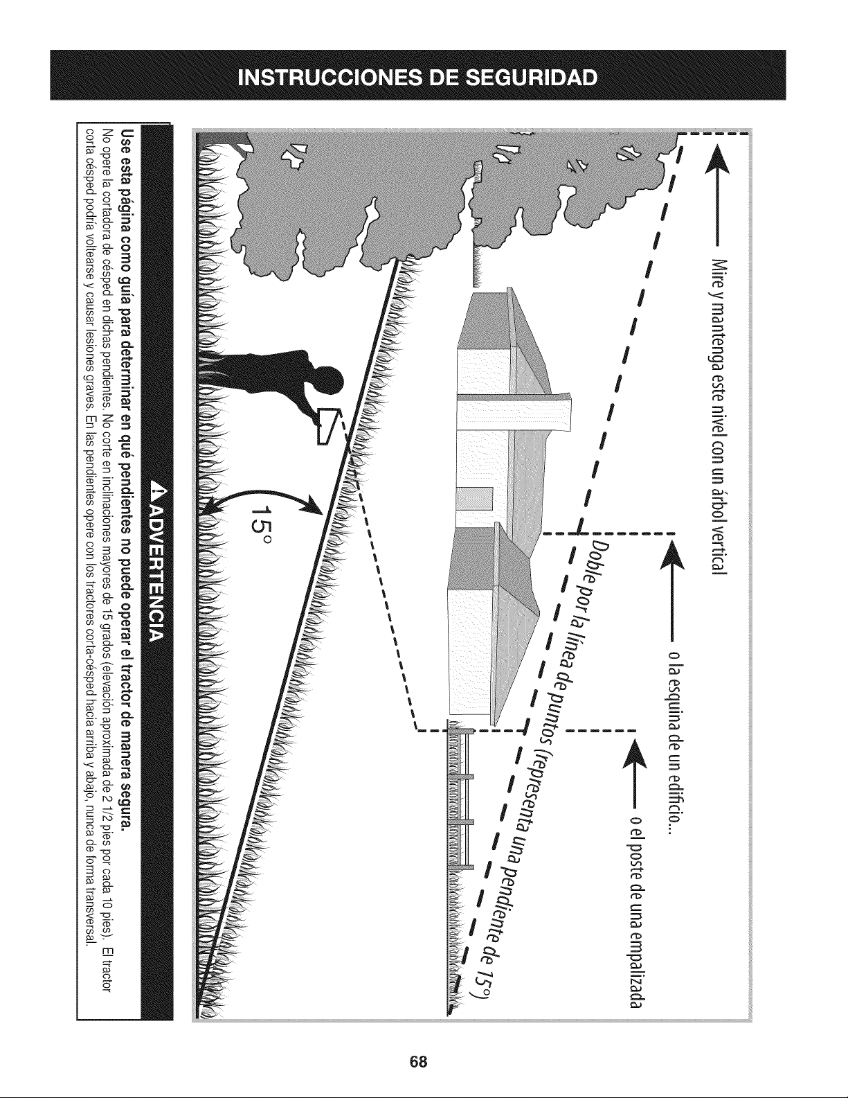
Z
mZ
c3
c3
_._ m.
c3 -_
c3
I
I
I
I
I
I
I
I
68

Estapgtginasemarch6intencionadamenteenblanco.
69
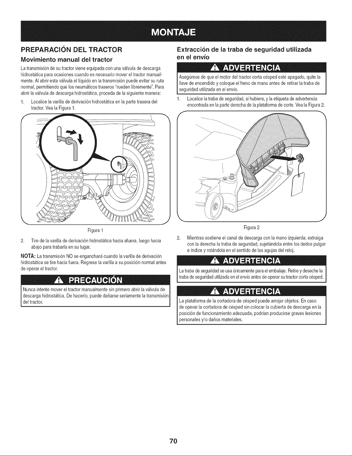
PREPARACION DEL TRACTOR
IViovirniento manual del tractor
Extracci6n de la traba de seguridad utilizada
en el envio
La transmisi6nde su tractorvieneequipadacon unav_lvulade descarga
hidrost_ticaparaocasionescuandoes necesariomoverel tractor manual-
mente.AI abrir esta v_lvula el I[quidoen la transmisi6npuedeevitar su ruta
normal,permitiendoque los neum_ticostraseros"ruedenlibremente".Para
abrir lav_lvula de descarga hidrost_tica,procedade la siguientemanera:
1. Localicelavarilla de derivaci6nhidrost_ticaen la partetraseradel
tractor.Veala Figura1.
AsegL]resede que el motordeltractor corta cespedeste apagado,quitela
Ilavede encendidoy coloqueelfreno de mano antesde retirarla trabade
seguridadutilizadaen el env[o.
1. Localicela trabade seguridad,si hubiere,y laetiquetade advertencia
encontradaen la partederechadela plataformade corte.Veala Figura2.
Figura 1
2. Tire de la varillade derivaci6nhidrost_ticahaciaafuera,luego hacia
abajoparatrabarla en su lugar.
NOTA: La transmisi6nNO se enganchar_cuandolavarilla de derivaci6n
hidrost&ticase tire hacia fuera.Regreselavarilla a su posici6nnormalantes
de operarel tractor.
Nuncaintentemoverel tractor manualmentesin primeroabrirla v&lvulade
descargahidrost_tica.Dehacerlo,puededaSarseseriamentelatransmisi6n
deltractor.
2,
Figura2
Mientrassostieneel canal de descargacon la manoizquierda,extraiga
con laderecha latrabade seguridad,sujet&ndolaentrelosdedos pulgar
e [ndicey rot_ndolaen el sentidode lasagujasdel reloj.
La trabade seguridadse usaQnicamenteparael embalaje.Retireydesechela
trabadeseguridadutilizadaen elenv[oantesdeoperarsutractorcortacesped.
La plataformade lacortadorade cespedpuedearrojarobjetos.En caso
de operarla cortadoradecesped sin colocar la cubiertade descargaen la
posici6nde funcionamientoadecuada,podr[anproducirsegraveslesiones
personalesy/o daSosmateriales.
7O
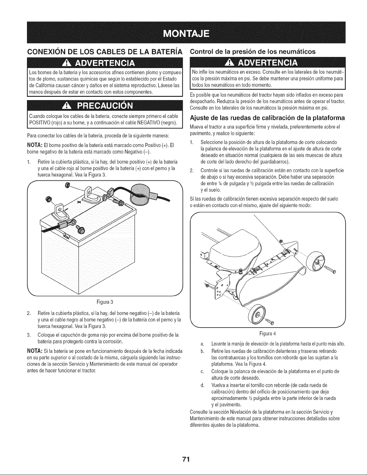
CONEXION DE LOS CABLES DE LA BATERIA
Los bornesde la bateriay losaccesoriosalines contienenplomoy compues-
tos de plomo,sustanciasquimicasque seg0nIo establecidopor el Estado
de Californiacausanc_ncery da_os en el sistemareproductivo.Laveselas
manosdespuesde estar en contactocon estoscomponentes.
Cuandocoloque loscablesde la bateria,conectesiempreprimeroel cable
POSITIVO(rojo)a su borne,y a continuaci6nel cableNEGATIVO(negro).
Paraconectar loscablesde la bateria,proceda de la siguientemanera:
NOTA: El bornepositivode la bateriaest_ marcadocomo Positivo(+). El
bornenegativode la bateriaest_marcadocomo Negativo(-).
1. Retirela cubiertapl_stica,si la hay,del bornepositivo (+)de la bateria
y unael cablerojo al bornepositivode la bateria(+) con el pernoy la
tuerca hexagonal.Veala Figura3.
f
Figura 3
2. Retirela cubiertapl_stica,si la hay,del bornenegativo(-) de labateria
y unael cablenegroal borne negativo(-) de la bateriacon el pernoy la
tuerca hexagonal.Veala Figura3.
3. Coloqueel capuch6nde gomarojopor encimadel bornepositivode la
bateriapara protegerlocontralacorrosi6n.
NOTA: Si la bateriase poneen funcionamientodespuesde lafecha indicada
en su partesuperior o al costado de lamisma,c_rguelasiguiendolasinstruc-
clonesde la secci6nServicio y Mantenimientode estemanualdel operador
antesde hacerfuncionarel tractor.
Control de la presi6n de los neumaticos
No infle losneum_ticosen exceso.Consulteen loslateralesde los neum_ti-
cos la presi6nm_ximaen psi. Se debe mantenerunapresi6nuniformepara
todos losneumAticosen todo momento.
Esposibleque losneum_ticosdeltractor hayansido infladosen excesopara
despacharlo.Reduzcala presi6nde los neum_ticosantesde operarel tractor.
Consulteen loslateralesde losneum_ticosla presi6n m_ximaen psi.
Ajuste de las ruedas de calibraci6n de la plataforma
Muevaeltractor a unasuperficiefirme y nivelada,preferentementesobreel
pavimento,y realiceIosiguiente:
1. Seleccionela posici6nde altura de la plataformade corte colocando
lapalancade elevaci6nde la plataformaen el ajustede alturade corte
deseadoensituaci6n normal(cualquierade las seismuescasde altura
de corte del lado derechodel guardabarros).
2. Controle si las ruedasde calibraci6nest_n en contactocon la superficie
de abajoo si hay excesivaseparaci6n.Debe haberunaseparaci6n
de entre1_de pulgaday Y2pulgadaentrelas ruedasde calibraci6n
y el suelo.
Si las ruedasdecalibraci6ntienen excesivaseparaci6nrespectodel suelo
o est_n en contactocon el mismo,ajustedel siguientemodo:
Figura4
a. Levantelamanijade elevaci6nde laplataformahastaelpuntomAsalto.
b. Retirelas ruedasde calibraci6ndelanterasytraseras retirando
lascontratuercasy los tornilloscon rebordeque lassujetana la
plataforma.Vea la Figura4.
c. Coloque lapalanca de elevaci6nde la plataformaen el puntode
altura de cortedeseado.
d. Vuelvaa insertarel tornillocon reborde(de cadaruedade
calibraci6n)dentrodel orificio de posicionamientoque deja
aproximadamenteY2pulgadaentrela parte inferiorde la rueda
y el pavimento.
Consultela secci6nNivelaci6nde la plataformaenla secci6nServicioy
Mantenimientode estemanualpara obtenerinstruccionesdetalladassobre
diferentesajustesde la plataforma.
71
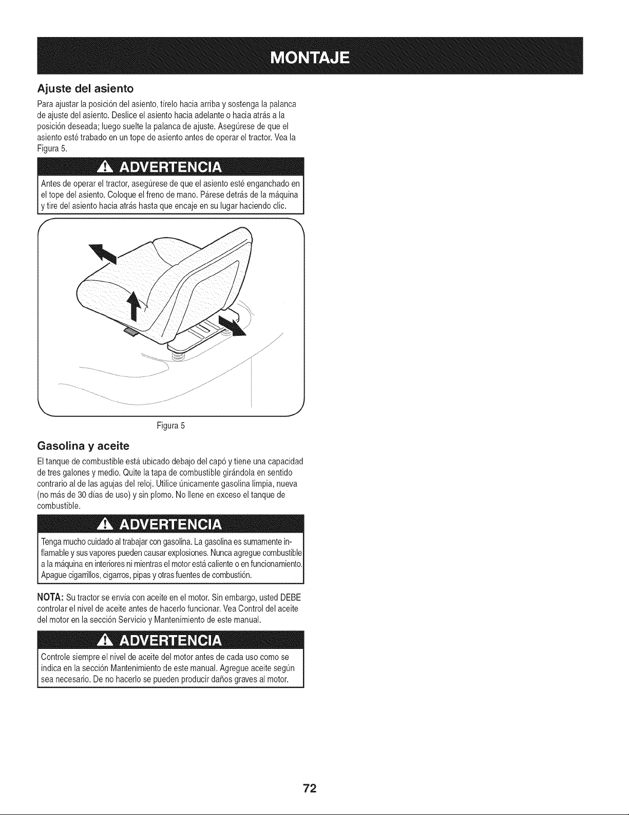
Ajuste del asiento
Para ajustarla posici6ndel asiento,firelo haciaarriba y sostengala palanca
de ajustedel asiento.Desliceel asientohaciaadelanteo hacia atr_s a la
posici6ndeseada;luegosueltela palancade ajuste.AsegQresedeque el
asientoeste trabadoen un tope de asiento antesde operareltractor. Veala
Figura5.
Antesde operareltractor, asegQresede que el asientoeste enganchadoen
I eltope del asiento.Coloqueel frenode mano.P&resedetr_sde la m&quina
[y tire del asientohacia arras hastaque encajeen su lugar haciendoclic.
" h
Figura5
Gasolina y aceite
Eltanquede combustibleest_ubicado debajodel cap6 y tiene unacapacidad
de tres galonesy medio.Quitela tapa de combustiblegir&ndolaen sentido
contrarioal de lasagujasdel reloj. UtiliceQnicamentegasolinalimpia, nueva
(no m&sde 30 dias de uso) y sinplomo. NoIleneen excesoel tanquede
combustible.
Tengamuchocuidadoaltrabajarcongasolina.La gasolinaessumamentein-
flamabley susvaporespuedencausarexplosiones.Nuncaagreguecombustible
a lam_quinaen interioresnimientrasel motorest&calienteo en funcionamiento.
Apaguecgarr os,cgarros,p pasyotrasfuentesde combust6n.
NOTA: Su tractorse envia con aceiteen el motor.Sinembargo,usted DEBE
controlarel nivelde aceiteantesde hacerlofuncionar.VeaControldel aceite
del motoren la secci6nServicioy Mantenimientode este manual.
Controlesiempreel nivelde aceitedel motorantesdecada uso comose
indicaen la secci6nMantenimientode estemanual.AgregueaceitesegQn
sea necesaro. De no hacero se puedenproducr daSosgravesa motor.
72
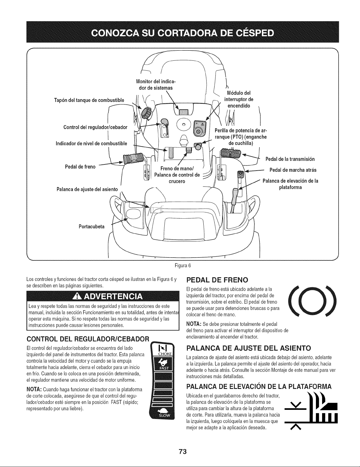
f
TapSndel tanque de combustible
Control del regulador/cebador
I
Indicador de nivel decombustible
Monitor del indica-
dot de sistemas
-___6dulo del
interruptorde
encendido
Perilla de potenciade ar-
ranque (PTO) (enganche
de cuchilla)
Pedalde freno
Palanca de ajuste del asiento
Freno de mano/
Palanca de control de
crucero
Pedal de la transmisiSn
Pedal de marcha atr_s
Palanca de elevaci6nde la
plataforma
Portacubeta
\
Figura 6
Los controlesy funcionesdeltractor corta cespedse ilustranen la Figura6 y
se describenen las p&ginassiguientes.
Leay respetetodaslas normasde seguridady las instruccionesdeeste
manual,incluidala secci6nFuncionamientoen su totalidad,antes de intentai
operaresta m&quina.Si no respetatodas las normasde seguridady las
instruccionespuedecausarlesionespersonales.
CONTROL DEL REGULADOR/CEBADOR
Elcontrol del regulador/cebadorseencuentradel lado
izquierdodel panelde instrumentosdel tractor. Estapalanca
controlalavelocidaddel motory cuando se la empuja
totalmentehacia adelante,cierra el cebador para un inicio
en frio. Cuandose Io colocaen una posici6ndeterminada,
el reguladormantieneunavelocidad de motoruniforme.
NOTA: Cuando hagafuncionarel tractorcon la plataforma
de corte colocada,asegQresede queel control del regu-
lador/cebadorestesiempreen laposici6n FAST(r_pido;
representadopot una liebre).
PEDAL DE FRENO
Elpedalde freno est_ubicado adelantea la
izquierdadeltractor,por encimadel pedalde
transmisi6n,sobreel estribo.El pedalde freno
se puedeusar para detencionesbruscaso para
colocar elfreno de mano.
NOTA: Se debe presionartotalmenteel pedal
del freno paraactivar el interruptordel dispositivode
enclavamientoal encendereltractor.
PALANCA DE AJUSTE DEL ASIENTO
La palancade ajustedel asientoest&ubicadadebajodel asiento,adelante
a laizquierda.La palancapermiteelajuste del asientodel operador,hacia
adelanteo haciaatr_s. Consultelasecci6n Montajede este manualpara vet
instruccionesm_sdetalladas.
PALANCA DE ELEVACION DE LA PLATAFORIVlA
Ubicadaen el guardabarrosderechodel tractor,
lapalancade elevaci6nde la plataformase
_P
utilizaparacambiar la altura de la plataforma
de corte.Para utilizarla,muevala palanca hacia
laizquierda,luegocol6quelaen la muescaque
mejorse adaptea la aplicaci6ndeseada. A
73
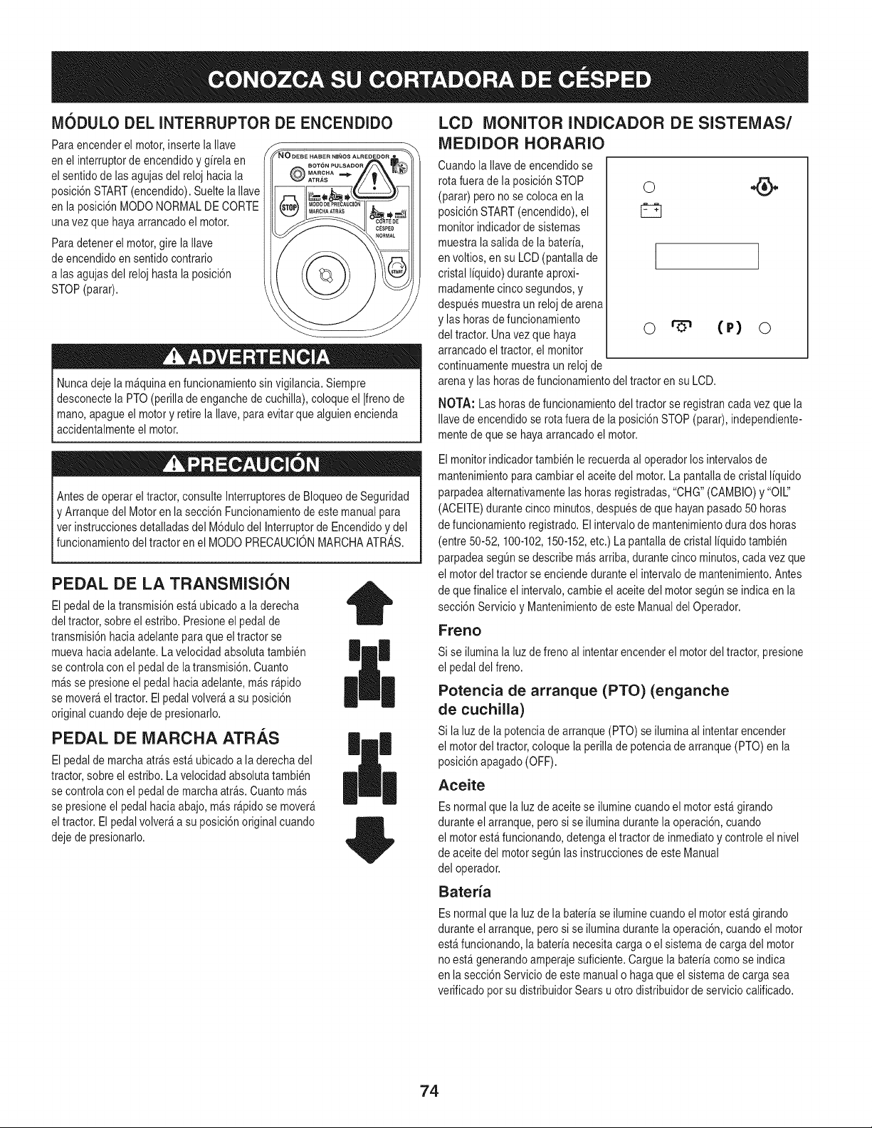
IVIODULO DEL INTERRUPTOR DE ENCENDIDO
Para encenderel motor,inserte la Ilave
en el interruptorde encendidoy girela en
el sentidode lasagujasdel reloj haciala
posici6nSTART(encendido).Sueltela Ilave
en la posici6nMODONORMALDE CORTE
unavez quehayaarrancadoel motor.
Para detenerel motor,gire la Ilave
de encendidoen sentido contrario
alas agujasdel reloj hasta la posici6n
STOP(parar).
Nuncadeje la m_quinaen funcionamientosin vigilancia.Siempre
desconectela PTO(perillade enganche de cuchilla),coloqueel Ifrenode
mano,apagueel motory retirela Ilave,para evitarque alguienencienda
accidentalmenteel motor.
Antesde operareltractor, consulteInterruptoresde Bloqueode Seguridad
y Arranquedel Motoren la secci6nFuncionamientode estemanualpara
vet instruccionesdetalladasdel M6dulodel Interrup!orde Encendidoy del
func onamento de tractor en e MODO PRECAUCON MARCHAATRAS.
PEDAL DE LA TRANSiVlISION
El pedalde la transmisi6nest_ubicadoa laderecha
del tractor,sobreel estribo.Presioneel pedalde
transmisi6nhaciaadelanteparaque eltractor se
muevahaciaadelante.La velocidadabsolutatambien
se controlacon el pedalde latransmisi6n.Cuanto
m_sse presioneel pedalhacia adelante,m_sr@ido
se mover_el tractor. Elpedalvolver_a su posici6n
originalcuandodeje de presionarlo.
PEDAL DE iVlARCHA ATRAS
El pedalde marchaarrasest_ubicado a la derechadel
tractor,sobre el estribo.Lavelocidadabsolutatambien
se controlacon el pedalde marchaarras.Cuantom_s
se presioneel pedalhaciaabajo,m_s r@idose mover_
eltractor. El pedalvolver_ a su posici6noriginal cuando
dejede presionarlo.
|
LCD MONITOR INDICADOR DE SISTEIVlAS/
iVlEDIDOR HORARIO
Cuandola Ilavede encendidose
rota fuerade la posici6nSTOP
(parar) pero no se coloca en la
posici6nSTART(encendido),el
monitor indicadorde sistemas
muestra lasalida de labateria,
en voltios, en su LCD(pantallade
cristal liquido) duranteaproxi-
madamentecincosegundos,y
despuesmuestraun relojde arena
y las horasde funcionamiento
del tractor. Unavezque haya
arrancadoel tractor,el monitor
continuamentemuestraun relojde
I
o (r) o
arenay las horasde funcionamientodel tractoren su LCD.
NOTA: Las horas de funcionamientodel tractorse registrancadavez que la
Ilavede encendidose rotafuera de la posici6nSTOP(parar), independiente-
mentede que se hayaarrancadoel motor.
Elmonitorindicadortambien le recuerdaal operadorlos intervalosde
mantenimientoparacambiarel aceitedel motor.La pantallade cristal liquido
parpadeaalternativamentelashorasregistradas,"CHG"(CAMBIO)y "Oil"
(ACEITE)durantecinco minutos,despuesde que hayanpasado50 horas
de funcionamientoregistrado.El intervalode mantenimientodura dos horas
(entre 50-52, 100-102,150-152,etc.) La pantallade cristal liquidotambien
parpadeasegL_nse describem_sarriba, durantecinco minutos,cadavez que
el motordel tractor se enciendeduranteel intervalode mantenimiento.Antes
de quefinalice el intervalo,cambieel aceitedel motorsegL_nse indica en la
secci6nServicioy Mantenimientode este Manualdel Operador.
Freno
Si se iluminala luzde freno al intentarencenderel motordel tractor,presione
el pedal del freno.
Potencia de arranque (PTO) (enganche
de cuchilla)
Si la luzde la potenciadearranque (PTO)se iluminaal intentarencender
el motordel tractor,coloque la perillade potenciade arranque(PTO) en la
posici6napagado(OFF).
Aceite
Esnormalque la luzde aceitese iluminecuandoel motorest_girando
duranteelarranque,perosi se iluminadurantela operaci6n,cuando
el motorest_ funcionando,detenga eltractor de inmediatoy controleel nivel
de aceitedel motorsegL_nlasinstruccionesde este Manual
del operador.
Bateria
Esnormalque la luzde la bateriase iluminecuandoel motorest_ girando
duranteelarranque,perosi se iluminadurantela operaci6n,cuandoel motor
est&funcionando,la baterianecesitacarga o el sistemade carga del motor
no est&generandoamperajesuficiente.Carguela bateriacomo se indica
en lasecci6n Serviciode estemanualo hagaque el sistemade carga sea
verificadopotsu distribuidorSears u otro distribuidorde servicio calificado.
74
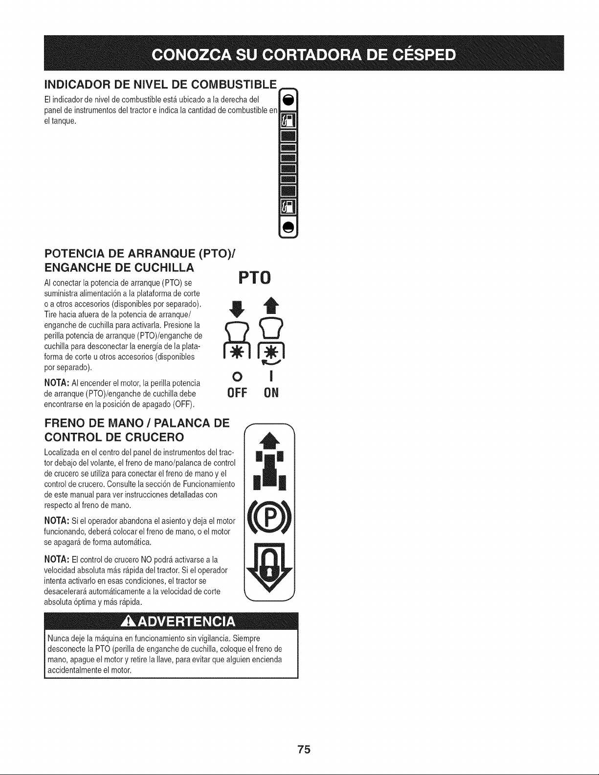
INDICADOR DE NIVEL DE COMBUSTIBLE
El indicadorde nivelde combustibleest_ ubicadoa la derechadel
panelde instrumentosdel tractor e indica la cantidadde combustibleen
eltanque.
POTENCIA DE ARRANQUE (PTO)/
ENGANCHE DE CUCHILLA
AI conectarla potenciadearranque(PTO) se
suministraalimentaci6na la plataformade corte
o a otros accesorios(disponiblespor separado).
Tire haciaafuerade lapotenciade arranque/
enganchedecuchilla paraactivarla. Presionela
perillapotenciade arranque(PTO)/enganchede
cuchillaparadesconectarla energiade la plata-
formade corte uotros accesorios(disponibles
pot separado).
NOTA: AI encenderel motor,la perillapotencia
de arranque(PTO)/enganchedecuchilladebe
encontrarseenla posici6nde apagado(OFF).
PTO
OFF ON
FRENO DE MANO / PALANCA DE
CONTROL DE CRUCERO
Localizadaenel centrodel panelde instrumentosdeltrac-
tordebajo del volante,el frenode mano/palancade control
de crucerose utiliza paraconectar elfrenode manoy el
controlde crucero.Consultelasecci6n de Funcionamiento
de este manualparavet instruccionesdetalladascon
respectoalfrenode mano.
NOTA: Si el operadorabandonael asientoy dejael motor
funcionando,deber_colocar elfreno de mano, o el motor
se apagar_deforma autom_tica.
NOTA: El controlde cruceroNOpodr_activarsea la
velocidadabsolutam_s r_pidadel tractor.Si el operador
intentaactivarloen esascondiciones,el tractor se
desacelerar_autom_ticamentea lavelocidad de corte
absoluta6primay m_s r_pida.
Nuncadeje la m_quinaen funcionamientosinvigilancia. Siempre
desconecte laPTO(perillade enganchede cuchilla,coloqueelfreno de
mano,apagueel motory retirela Ilave,para evitarque alguienencienda
accidentalmenteel motor.
75
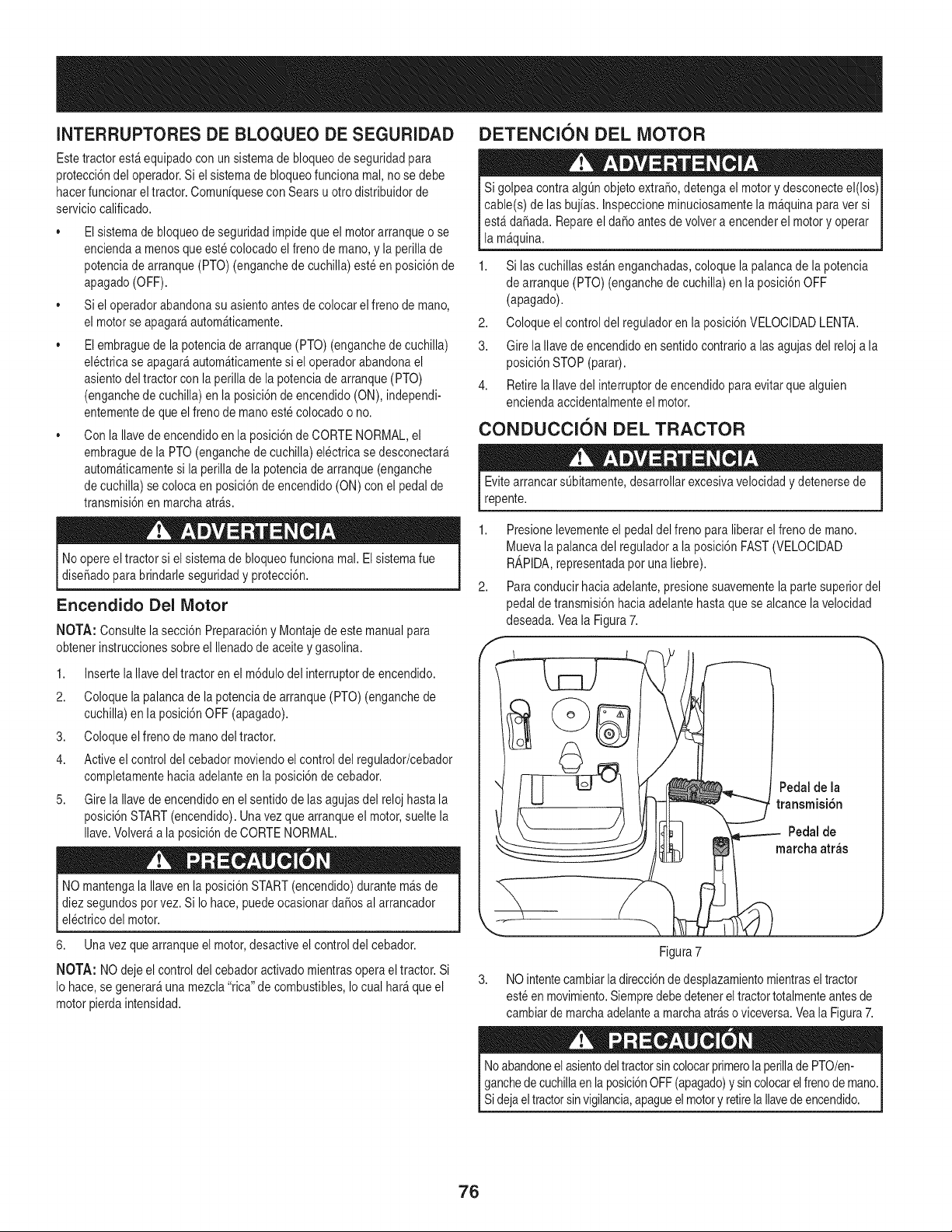
INTERRUPTORESDE BLOQUEO DE SEGURIDAD
Este tractorest_equipadocon un sistemade bloqueode seguridadpara
protecci6ndel operador.Si el sistemade bloqueofuncionamal,no se debe
hacerfuncionar eltractor.Comuniquesecon Sears u otro distribuidorde
serviciocalificado.
• Elsistemade bloqueode seguridadimpideque el motorarranqueo se
enciendaa menosque este colocadoel frenode mano, y la perillade
potenciade arranque(PTO) (enganchede cuchilla)este en posici6nde
apagado(OFF).
• Siel operadorabandonasu asientoantesde colocar el frenode mano,
el motorse apagar_autom_ticamente.
• Elembraguede la potenciadearranque (PTO)(enganchede cuchilla)
electricase apagar_autom_ticamentesi el operadorabandonael
asientodel tractorcon la perillade la potenciade arranque(PTO)
(enganchede cuchilla)en la posici6nde encendido(ON), independi-
entementede queel frenode mano estecolocadoo no.
• Con la Ilavede encendidoenla posici6nde CORTENORMAL,el
embraguede la PTO(enganchedecuchilla)el@tricase desconectar_
autom_ticamentesi la perillade la potenciade arranque(enganche
de cuchilla)se colocaen posici6nde encendido (ON)con el pedalde
transmisi6nen marchaarras.
DETENCION DEL MOTOR
Si golpeacontraalgQnobjetoextra,o, detengael motory desconecteel(los)
cable(s) de las bujias. Inspeccioneminuciosamentela m_quinaparaver si
est_da6ada. Repareel da6o antesde volvera encenderel motoryoperar
la m_quina.
1. Si las cuchillasest_nenganchadas,coloque la palancade lapotencia
de arranque(PTO) (enganchede cuchilla)en la posici6nOFF
(apagado).
2. Coloqueel control del reguladoren la posici6nVELOCIDADLENTA.
3. Gire laIlavede encendidoensentidocontrarioa lasagujas del reloja la
posici6nSTOP (parar).
4. RetirelaIlavedel interruptorde encendidoparaevitarque alguien
enciendaaccidentalmenteel motor.
CONDUCCION DEL TRACTOR
EvitearrancarsQbitamente,desarrollarexcesivavelocidady detenersede
repente.
Noopereel tractorsi el sistemade bloqueofuncionareal.Elsistemafue
dise_adopara brindarleseguridady )rotecci6n.
Encendido Del Motor
NOTA: Consultelasecci6n Preparaci6ny Montajedeeste manualpara
obtenerinstruccionessobre el Ilenadode aceiteygasolina.
1. Insertela Ilavedel tractoren el m6dulodel interruptorde encendido.
2. Coloquela palancade lapotenciade arranque(PTO) (enganchede
cuchilla)en la posici6nOFF (apagado).
3. Coloqueelfreno demano deltractor.
4. Activeel control del cebadormoviendoelcontrol del regulador/cebador
completamentehacia adelanteenla posici6nde cebador.
5. Gire la Ilavede encendidoen el sentido de las agujasdel reloj hasta la
posici6nSTART(encendido).Unavez que arranqueel motor,sueltela
Ilave.Volver_a la posici6nde CORTENORMAL.
NO mantengala Ilaveen la posici6nSTART(encendido)durante m_s de
diezsegundosporvez. Si Io hace, puedeocasionarda6osal arrancador
electricodel motor.
6. Unavez quearranque el motor,desactiveel controldel cebador.
NOTA: NO deje el control del cebadoractivadomientrasoperael tractor.Si
Io hace,se generar_una mezcla"rica"de combustibles,Io cual har_ queel
motorpierdaintensidad.
2,
Presionelevementeel pedaldel freno paraliberarel frenode mano.
Mueva la palancadel reguladora la posici6nFAST(VELOCIDAD
R_,PIDA,representadapot una liebre).
Paraconducirhaciaadelante,presionesuavementela partesuperiordel
pedal de transmisi6nhacia adelantehastaquese alcance lavelocidad
deseada.Veala Figura7.
Pedalde la
transmisi6n
Pedalde
marcha arras
Figura7
3. NO intentecambiarla direcci6nde desplazamientomientrasel tractor
esteen movimiento.Siempredebe detenerel tractortotalmenteantesde
cambiarde marchaadelantea marchaarraso viceversa.Veala Figura7.
Noabandoneelasientodeltractorsincolocarprimerola perillade PTO/en- j
ganchede cuchillaen la posici6nOFF (apagado)y sincolocarelfrenode mano.
I
S de a e tractorsnv g anca, apaguee motory retre a avedeencenddo. j
76
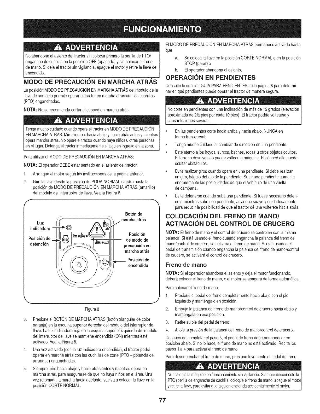
Noabandoneelasiento del tractorsin colocarprimerola perillade PTO/
enganchede cuchillaen la posici6nOFF (apagado)y sin colocarel freno
de mano.Si deja eltractor sinvigilancia,apagueel motory retirela Ilavede
encendido.
MODO DE PRECAUCION EN MARCHA ATR._,S
La posici6nMODODE PRECAUClONENMARCHAATRASdel m6dulode la
Ilavede contactopermiteoperarel tractor en marchaarrascon las cuchillas
(PTO)enganchadas.
NOTA: Nose recomiendacortarel cesped en marchaarras.
Tengamuchocuidadocuandoopereel tractoren MODODE PRECAUClON
ENMARCHAATRAS.Miresiemprehaciaabajoy haciaatr&santesy mientras
opera marchaatr&s.Noopereeltractorcuandohayanifiosu otraspersonas
en ellugar.Detengaeltractorinmediatamentesi alguieningresaen lazona.
Para utilizarel MODO DE PRECAUCIONENMARCHAATRAS:
NOTA: El operadorDEBEestar sentadoen el asientodel tractor.
1. Arranqueel motorsegQnlas instruccionesde lapagina anterior.
2. Gire la Ilavedesde la posici6nde PODANORMAL(verde)hastala
posici6nde MODODE PRECAUCIONEN MARCHAATRAS(amarillo)
del m6dulodel interruptorde Ilave.Veala Figura8.
indicadora
Posici6nde
detenci6n
Bot6n de
Lt marcha atr_s
[FF Posici6n
!I_ _,_i .... de modo de
[[_ precauci6nen
Figura8
3. Presioneel BOTONDEMARCHAATRAS(bot6ntriangularde color
naranja)en la esquinasuperiorderechadel m6dulodel interruptorde
Ilave.La luzindicadorarojaen la esquinasuperiorizquierdadel m6dulo
del interruptorde Ilavese mantieneencendida(ON) mientraseste
activado.Veala Figura8.
4. Unavez activado(con la luzindicadoraencendida),eltractor podr&
operaren marchaatr_s con lascuchillasde corte (PTO- potenciade
arranque)enganchadas.
5. Siempremirehaciaabajo y haciaatr_s antesy mientrasoperaen
marchaart&s,paraasegurarsede queno hayanifiosen el&tea. Una
vez retomadala marchahaciaadelante,vuelvaa colocar la Ilaveenla
posici6nCORTENORMAL.
ElMODODE PRECAUCIONEN MARCHAATRASpermaneceactivadohasta
que:
a. Se coloca la Ilaveen la posici6nCORTENORMALo enla posici6n
STOP (parar)o
b. El operadorabandonael asiento.
OPERACION EN PENDIENTES
Consultela secci6nGU[APARAPENDIENTESen la pagina8 paradetermi-
naten que pendientespuedeoperarel tractorde manerasegura.
No corte en pendientescon una inclinaci6nde m&sde 15grados (elevaci6n
aproximadade 2Y2pies pot cada10 pies). El tractor podriavoltearsey
causar lesionesseveras.
®
®
En laspendientescorte haciaarribay haciaabajo,NUNCAen
formatransversal.
Tengamuchocuidadoal cambiarde direcci6nen unapendiente.
Esteatentoa los hoyos,surcos, baches,rocas u otros objetosocultos.
Elterreno desniveladopuedevoltear la m_quina.El cesped alto puede
ocultar obst_culos.
• Eviterealizargiros cuandoopereen una pendiente.Si debe realizar
un giro,h_galodebajode la pendiente.Subiruna pendienteaumenta
enormementelasposibilidadesdeque elvehiculode unavuelta
de campana.
• Evitedetenersecuandosubauna pendiente.Si fuese necesariodeten-
erse mientrassubeuna pendiente,arranque suavey cuidadosamente
para reducirla posibilidadde que el tractor de unavolteretahaciaarras.
COLOCACION DEL FRENO DE MANO/
ACTIVACION DEL CONTROL DE CRUCERO
NOTA: Elfrenode manoy el controlde crucerose controlanconla misma
palanca.Siest_ usandoel frenocuandoenganchala palancadel freno de
mano/controlde crucero,se activar&el frenode mano.Si est_usandoel
pedalde transmisi6ncuandoenganchalapalanca del frenode mano/control
de crucero,se activar_el controlde crucero.
Freno de rnano
NOTA: Si el operadorabandonael asientoy deja el motorfuncionando,
deber_ colocarel frenode mano,o el motorse apagar_de formaautom_tica.
Para
1.
colocarel frenode mano:
Presioneel pedaldel frenocompletamentehaciaabajocon el pie
izquierdoy mantengaloen posici6n.
2. Empujela palancadel frenode mano/controldecrucerohaciaabajo y
mantengalaen esa posici6n.
3. Retiresu pie del pedal defreno.
4. Afloje la presi6nde la palancadel freno de mano/controlde crucero.
Despuesde completarel paso3, el pedalde freno debepermaneceren
posici6nabajo.Si no Io hace,elfreno de mano no est_activado. Repitalos
pasos1a 4 para activarel freno de mano.
Paradesengancharelfreno de mano, presionelevementeel pedalde freno.
Nuncadejela m&quinaenfuncionamientosinvigilancia.Siempredesconectela
PTO(perillade enganchede cuchilla,coloqueelfrenode mano,apagueel moto
y retirela Ilave,paraevitarquealguienenciendaaccidentalmenteel motor.
77
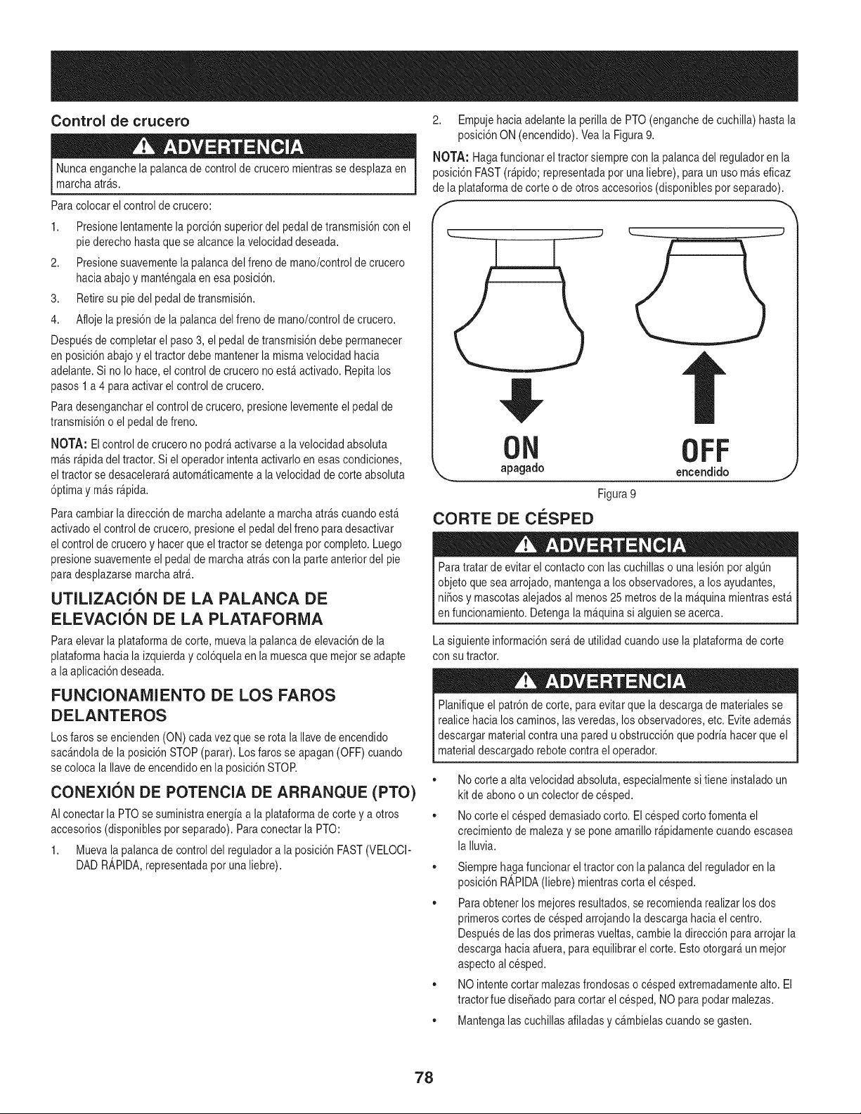
Control de crucero
Nuncaenganchela palancade control de crucero mientrasse desplazaen
marchaarras.
Para colocarel controlde crucero:
1. Presionelentamentelaporci6nsuperiordel pedalde transmisi6ncon el
pie derechohastaque se alcancela velocidaddeseada.
2. Presionesuavementela palancadel frenode mano/controlde crucero
haciaabajoy mantengalaen esa posici6n.
3. Retiresu pie del pedaldetransmisi6n.
4. Afloje la presi6nde la palancadel frenode mano/controlde crucero.
Despuesde completarel paso3, el pedal de transmisi6ndebepermanecer
en posici6nabajoy el tractordebe mantenerla mismavelocidad hacia
adelante.Si no Io hace,el controlde crucerono est_ activado.Repitalos
pasos1 a 4 paraactivarel control de crucero.
Para desengancharel controlde crucero,presionelevementeel pedal de
transmisi6no elpedal de freno.
NOTA: Elcontrol de crucerono podr_activarsea lavelocidadabsoluta
m_sr@ida del tractor.Si el operadorintentaactivarloen esascondiciones,
eltractor se desacelerar_autom_ticamentea la velocidadde corte absoluta
6primay m_s r@ida.
Para cambiarladirecci6nde marchaadelantea marchaarrascuandoest_
activadoel controlde crucero,presioneel pedaldel frenopara desactivar
el controlde cruceroy hacerque el tractorse detengapot completo.Luego
presionesuavementeel pedal de marchaarrascon la parteanteriordel pie
para desplazarsemarchaatr_.
UTILIZACION DE LA PALANCA DE
ELEVACION DE LA PLATAFORiVlA
Para elevarla plataformade corte, muevala palancade elevaci6nde la
plataformahacia la izquierday col6quelaen la muescaque mejorse adapte
a la aplicaci6ndeseada.
FUNCIONANIIENTO DE LOS FAROS
DELANTEROS
Los farosse encienden(ON) cadavez queserota la Ilavedeencendido
sac_ndolade la posici6nSTOP (parar).Los faros se apagan(OFF)cuando
se coloca la Ilavede encendidoenla posici6nSTOR
CONEXION DE POTENCIA DE ARRANQUE (PTO)
AIconectar la PTOsesuministraenergiaa la plataformade cortey a otros
accesorios(disponiblespotseparado).Paraconectarla PTO:
1. Muevala palancade controldel reguladora la posici6nFAST(VELOCI-
DAD R_,PIDA,representadapotuna liebre).
2. Empujehaciaadelantela perillade PTO(enganchede cuchilla)hasta la
posici6nON (encendido).Veala Figura9.
NOTA: Hagafuncionarel tractor siemprecon la palancadel reguladorenla
posici6nFAST(r@ido; representadapor unaliebre), para un uso m_seficaz
de la plataformade corte o de otrosaccesorios(disponiblespot separado).
ON
apagado
OFF
encendido
Figura9
J
CORTE DE CO:SPED
Paratratarde evitarel contactocon lascuchillaso una lesi6n potalgL_n
objeto quesea arrojado,mantengaa los observadores,a losayudantes,
ni_osy mascotasalejadosal menos25 metrosde la m_quinamientrasest_
en funcionamiento.Detengala m_quinasi alguiense acerca.
La siguienteinformaci6nser_de utilidadcuandouse laplataformadecorte
con su tractor.
Planifiqueel patr6nde corte,para evitarque ladescargade materialesse
realice hacialoscaminos,lasveredas, los observadores,etc. Eviteadem_s
descargarmaterialcontrauna paredu obstrucci6nquepodria hacerque el
materialdescargadorebotecontrael operador.
• No corte a alta velocidadabsoluta,especialmentesi tiene instaladoun
kit deabonoo un colectorde cesped.
• No corte el cespeddemasiadocorto. Elcesped cortofomenta el
crecimientode malezay se pone amarillor@idamentecuandoescasea
la Iluvia.
• Siemprehagafuncionareltractor con la palanca del reguladoren la
posici6nR_,PIDA(liebre) mientrascorta el cesped.
• Paraobtener losmejoresresultados,se recomiendarealizarlosdos
primeroscortes de cespedarrojandoladescarga haciael centro.
Despuesde las dosprimerasvueltas,cambie ladirecci6npara arrojarla
descarga haciaafuera,para equilibrarel corte. Estootorgar_un mejor
aspectoalcesped.
• NO intentecortar malezasfrondosaso cespedextremadamentealto. El
tractorfue dise_adopara cortarel cesped,NO parapodarmalezas.
,, Mantengalascuchillasafiladasy c_mbielascuandose gasten.
78
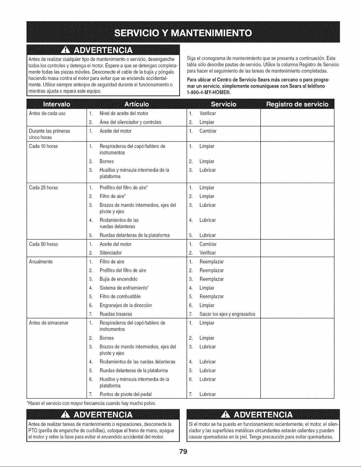
Antesde realizarcualquiertipo de mantenimientoo servicio,desenganche
todos loscontrolesy detenga el motor.Esperea que sedetengancompleta-
mentetodaslas piezasm6viles.Desconecteel cablede la bujia y p6ngalo
haciendomasacontrael motorpara evitarque se enciendaaccidental-
mente.Utilicesiempreanteojosde seguridadduranteel funcionamientoo
mientrasajustao repara este equipo.
Antesde cada uso 1. Nivelde aceitedel motor
2. Areadelsilenciadorycontroles
Siga el cronogramade mantenimientoque se presentaa continuaci6n.Esta
tabla s61odescribepautasde servicio.Utilice la columnaRegistrode Servicio
para hacerel seguimientodelastareas de mantenimientocompletadas.
Para ubicar el Centro de Servicio Sears m_s cercano o para progra-
mar un servicio, simplemente comuniquesecon Sears al tel_fono
1-800-4-MY-HOME®.
1,
2.
1.
Durantelas primeras 1. Aceite del motor
cinco horas
Cada10 horas 1. Limpiar1. Respiraderosdel cap6/tablerode
instrumentos
2. Bornes
3. Husillosy mensulaintermediade la
plataforma
1. Prefiltrodel filtro de aire*
2. Filtrode aire*
3. Brazosde mandointermedios,ejes del
pivotey ejes
4. Rodamientosdelas
ruedasdelanteras
5. Ruedasdelanterasdela plataforma
1. Aceite del motor
2. Silenciador
1. Filtrode aire
2. Prefiltrodel filtro de aire
3. Bujia de encendido
4. Sistemadeenfriamiento*
5. Filtrode combustible
6. Engranajesdela direcci6n
7. Ruedastraseras
1. Respiraderosdel cap6/tablerode
instrumentos
2. Bornes
3. Brazosde mandointermedios,ejes del
pivotey ejes
4. Rodamientosde lasruedasdelanteras
5. Ruedasdelanterasde la plataforma
6. Husillosy mensulaintermediade la
plataforma
Cada25 horas
Cada50 horas
Anualmente
Antesde almacenar
7. Puntosdepivotedel pedal
*Hacerel serviciocon mayorfrecuenciacuandohay muchopolvo.
Antesde realizartareasde mantenimientoo reparaciones,desconectela
PTO(perilla de enganchede cuchillas),coloqueel frenode mano,apague
el motory retirela Ilaveparaevitarel encendidoaccidentaldel motor.
2,
3.
1,
2.
3.
Verificar
Limpiar
Cambiar
Limpiar
Lubricar
Limpiar
Limpiar
Lubricar
Lubricar
5. Lubricar
1. Cambiar
2. Verificar
1. Reemplazar
2. Reemplazar
3. Reemplazar
4. Limpiar
5. Reemplazar
6. Limpiar
7. Sacar los ejesy engrasarlos
1. Limpiar
2,
3.
4,
5.
6.
Limpiar
Lubricar
Lubricar
Lubricar
Lubricar
Lubricar
Si el motorse ha puestoen funcionamientorecientemente,el motor,el silen-
ciadory las superficiesmet_licascircundantesestar&ncalientesy pueden
[ causarquemadurasen a pe. Tengaprecauc6n paraevtar quemaduras.
79
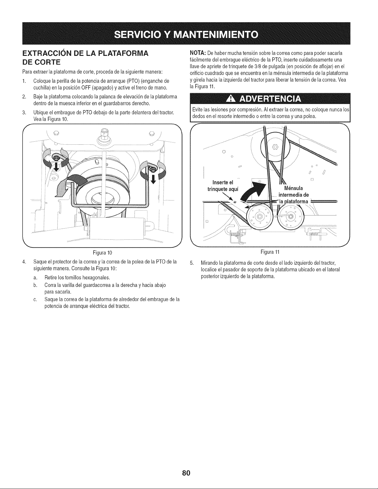
EXTRACCI6N DE LA PLATAFORiVlA
DE CORTE
Para extraerla plataformadecorte, procedade la siguientemanera:
1. Coloquela perillade lapotenciade arranque(PTO) (enganchede
cuchilla)en la posici6nOFF (apagado)y activeel frenode mano.
2. Baje la plataformacolocandola palancade elevaci6nde la plataforma
dentrode la muescainferioren el guardabarrosderecho.
3. Ubiqueelembraguede PTOdebajode la partedelanteradel tractor.
Veala Figura10.
f
i
Figura 10
Saqueel protectorde la correay la correade la poleade la PTOde la
siguientemanera.Consultela Figura 10:
a. Retirelostomilloshexagonales.
b. Corra lavarilla del guardacorreaa la derechay haciaabajo
para sacarla.
c. Saque lacorreade la plataformade alrededordel embraguede la
potenciade arranqueelectricadel tractor.
NOTA: Dehabermucha tensi6nsobre la correacomo para podersacarla
f_cilmentedel embragueelectrico de la PTO,insertecuidadosamenteuna
Navede aprietede trinquetede 3/8de pulgada(en posici6ndeaflojar)en el
orificiocuadradoquese encuentraen la mensulaintermediade laplataforma
y gfrelahaciala izquierdadel tractor para liberarla tensi6nde la correa.Vea
la Figura11.
Evitelas lesionespor compresi6n.AIextraer la correa,no coloque nunca los
dedos en el resorte intermedioo entrela correay unapolea.
0
o
Inserte el k :_
trinquete aquf M_nsula
intermediade
)lataforma
\
8O
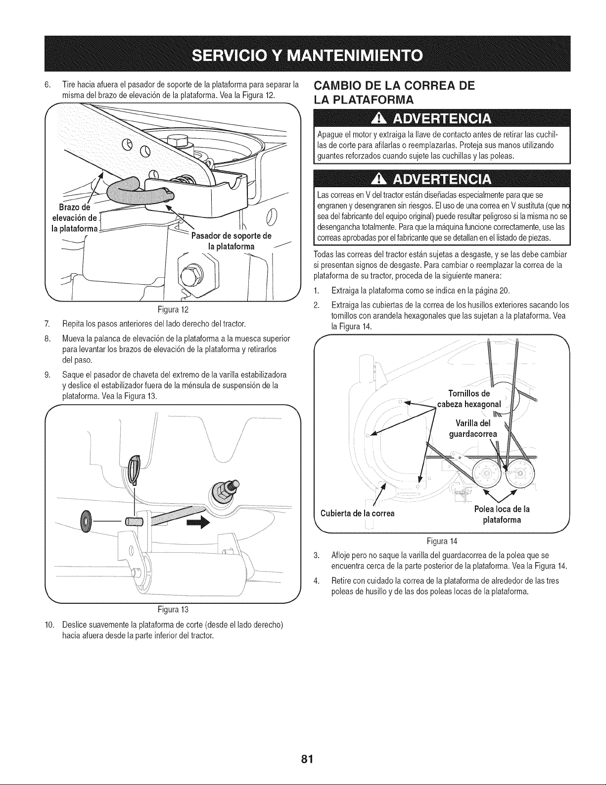
6,
Tire haciaafuerael pasadorde soporte de la plataformaparasepararla
mismadel brazo de elevaci6nde la plataforma.Veala Figura12.
CAiVlBIO DE LA CORREA DE
LA PLATAFORMA
0
de soportede
la plataforma
Figura 12
7. Repita lospasosanterioresdel lado derechodel tractor.
8. Muevala palancade elevaci6nde la plataformaa la muescasuperior
para levantarlos brazosde elevaci6nde la plataformay retirarlos
del paso.
9. Saqueel pasadorde chavetadel extremode lavarilla estabilizadora
y deslice el estabilizadorfuerade la mensulade suspensi6nde la
plataforma.Vea la Figura13.
A
/
!
..............................................................1!
H
/
Figura 13
10. Deslicesuavementela plataformade corte (desdeel lado derecho)
haciaafueradesde la parteinferiordel tractor.
Apagueel motory extraigala lave de contactoantes de retirar lascuchil-
las de corte para afilarlaso reemplazarlas.Protejasus manos utilizando
guantesreforzadoscuandosujetelascuchillas y laspoleas.
Las correasen V deltractorest_ndiseSadasespecialmenteparaquese
engraneny desengranensin riesgos.Elusodeunacorreaen Vsustituta(quenc
seadel fabricantedelequipooriginal)puederesultarpeligrososi lamismano se
desenganchatotalmente.Paraquelam&quinafuncionecorrectamente,uselas
correasaprobadas_orelfabricantequesedetallanen ellistadode piezas.
Todaslascorreasdel tractor est_nsujetasa desgaste,y se las debe cambiar
si presentansignosde desgaste.Paracambiaro reemplazarla correade la
plataformade su tractor,procedade lasiguiente manera:
1. Extraigala plataformacomo se indica en la p£gina20.
2. Extraigalas cubiertasde la correade loshusillosexterioressacandolos
tornilloscon arandela hexagonalesque lassujetana la plataforma.Vea
la Figura14.
Cubiertade la correa
Polea Ioea de [a
Figura14
3. Afloje pero no saque lavarilla del guardacorreade lapolea quese
encuentracercade la parteposteriorde la plataforma.Veala Figura14.
4. Retirecon cuidado la correade la plataformadealrededordelas tres
poleasde husilloy delas dos poleasIocas de laplataforma.
81
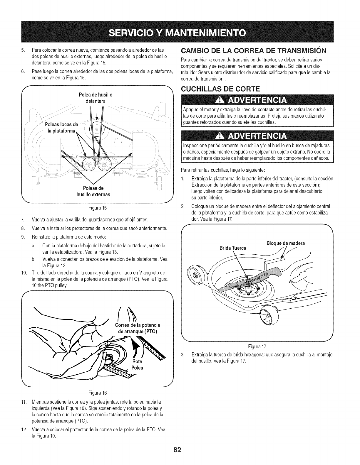
5. Para colocarla correanueva,comiencepas&ndolaalrededorde las
dos poleasde husilloexternas,luegoalrededordela polea de husillo
delantera,como seve en la Figura15.
6. Pase luegola correaalrededorde las dos poleas Iocasde la plataforma,
comose ve en la Figura15.
'• i,,
7,
8.
9.
10.
F
Poleade husillo
delantera
Poleas de
husilloexternas
Figura 15
J
Vuelvaa ajustar la varilladel guardacorreaque afloj6 antes.
Vuelvaa instalarlos protectoresde lacorrea quesac6 anteriormente.
Reinstalela plataformade estemodo:
a. Con la plataformadebajodel bastidorde lacortadora, sujetela
varillaestabilizadora.Veala Figura 13.
b. Vuelvaa conectar losbrazos de elevaci6nde la plataforma.Vea
la Figura12.
Tire del ladoderechode lacorrea y coloqueel lado en V angostode
la mismaen la poleade la potenciadearranque (PTO).Vea la Figura
16.thePTOpulley.
Correa de la potencia
de arranque (PTO)
Polea
CAlVlBIO DE LA CORREA DE TRANSMISION
Paracambiarla correadetransmisi6ndel tractor,se debenretirarvarios
componentesy se requierenherramientasespeciales.Solicite a un dis-
tribuidor Sears uotto distribuidorde serviciocalificadoparaque lecambie la
correade transmisi6n..
CUCHILLAS DE CORTE
Apagueel motory extraigala Ilavede contactoantes de retirar lascuchil-
las de corte para afilarlaso reemplazarlas.Protejasus manos utilizando
guantesreforzadoscuandosujetelas cuchillas.
Inspeccioneperi6dicamentela cuchillay/o el husilloen buscade rajaduras
o da6os, especialmentedespuesde golpear un objetoextra_o.No operela
m_quinahastadespuesde haber reemplazadoloscomponentesdaSados.
Pararetirar lascuchillas,haga Io siguiente:
1. Extraigala plataformade la parteinferiordel tractor,(consultelasecci6n
Extracci6nde la plataformaen partesanterioresde estasecci6n);
luegovoltee con delicadezala plataformapara dejar al descubierto
su parteinferior.
2. Coloque un bloquede maderaentreel deflectordel alojamientocentral
de la plataformay la cuchilladecorte, para que actL_ecomoestabiliza-
dor. Veala Figura17.
f
Brida Tuerca
Bloquede madera
J
Figura17
3. Extraigala tuerca de brida hexagonalqueasegura lacuchillaal montaje
del husillo.Veala Figura17.
.... J
Figura 16
11. Mientrassostiene la correa y la poleajuntas,rote la poleahaciala
izquierda(Vea la Figura16). Siga sosteniendoy rotandola poleay
la correahastaque la correase enrolletotalmenteen la poleade la
potenciade arranque(PTO).
12. Vuelvaa colocar el protectorde la correade lapolea de la PTO.Vea
la Figura10.
82
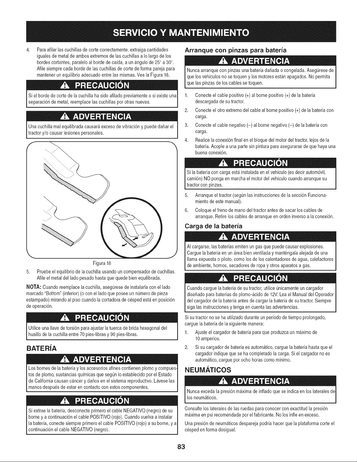
4,
Paraafilar lascuchillasde corte correctamente,extraigacantidades
igualesde metalde ambosextremosde lascuchillasa Io largo de los
hordescortantes,paraleloal hordede ca[da, a un &ngulode 25° a 30°.
Afilesiemprecada bordede las cuchillasde corte de forma parejapara
mantenerun equilibrioadecuadoentrelas mismas.Vea la Figura18.
Si el hordede corte de la cuchilla ha sidoafilado previamenteo si existe una
separaci6nde metal,reemplacelas cuchillaspot otras nuevas.
Unacuchilla mal equilibradacausar&excesode vibraci6ny puededaSarel
tractor y/o causar lesionespersonales.
Figura 18
5. Pruebeel equilibriode lacuchilla usandoun compensadorde cuchillas.
Afileel metal del ladopesadohastaque quedebienequilibrada.
NOTA: Cuando reemplacelacuchilla, asegLiresede instalarlacon ellado
marcado"Bottom"(inferior)(o con el ladoque poseeun nL_merode pieza
estampado)mirandoal pisocuandola cortadorade cesped est_en posici6n
de operaci6n.
Utilice unaIlavede torsi6n para ajustar la tuercade brida hexagonaldel
husillode lacuchillaentre 70 pies-librasy 90 pies-libras.
BATER[A
Los bornesde la bater[ay losaccesoriosalines contienenplomoy compues-
tos de plomo,sustanciasqu[micasque seg0nIo establecidopor el Estado
de Californiacausanc&ncerydaSosen el sistemareproductivo.Laveselas
manosdespuesde estar en contactocon estoscomponentes.
Si extrae la bater[a,desconecteprimeroel cable NEGATIVO(negro)de su I
borney a continuaci6nel cable POSlTIVO(rojo). Cuandovuelvaa instalar
la bater[a,conectesiempreprimeroel cable POSITIVO(rojo) a su borne,y a
cont nuac6n e cab e NEGATVO (negro). I
Arranque con pinzas para bateria
Nuncaarranquecon pinzasuna bater[adaSadao congelada. AsegL_resede
que losveh[culosno se toqueny los motoresest_n apagados.Nopermita
que las pinzasde loscables se toquen.
1. Conecteel cablepositivo (+) al bornepositivo(+) de labater[a
descargadade su tractor.
2. Conecteel otro extremodel cableal borne positivo(+)de la bater[acon
carga.
3. Conecteel cablenegativo(-) al borne negativo(-) de la bater[acon
carga.
4. Realicelaconexi6nfinal en el bloquedel motordel tractor,lejos de la
bater[a.Acople a una partesin pinturapara asegurarsede que hayauna
buenaconexi6n.
Si la bater[aconcarga est&instaladaen elveh[culo(es decirautom6vil,
cami6n)NO ponga en marchael motordel veh[culocuandoarranquesu
tractorcon pinzas.
5. Arranqueel tractor (segQnlasinstruccionesde lasecci6n Funciona-
mientode estemanual).
6. Coloqueel frenode manodel tractor antesde sacar los cables de
arranque.Retirelos cables de arranqueen ordeninversoa la conexi6n.
Carga de la bateria
AI cargarse,las bater[asemitenun gas que puedecausarexplosiones.
Carguela bater[aen un &teabien ventiladay mantengalaalejada de una
llamaexpuestao piloto,comolosde los calentadoresde agua, calefactores
de ambiente,hornos,secadoresde ropay otros aparatosa gas.
Cuandocargue labater[ade sutractor, utiliceOnicamenteun cargador
diseSadopara hater[asde plomo-_cidode 12V.Leael Manualdel Operador
del cargadorde la bater[aantesde cargarla bater[adesu tractor.Siempre
siga las instruccionesy tenga en cuentalasadvertencias.
Si su tractorno se ha utilizadoduranteun per[odode tiempoprolongado,
cargue labater[ade lasiguiente manera:
1. Ajusteel cargadorde bater[apara que produzcaunm_ximode
10amperios.
2. Si su cargadorde bater[aes autom&tico,carguela bater[ahastaque el
cargadorindiqueque se ha completadola carga. Si el cargadorno es
autom_tico,carguepot ocho horascomo m[nimo.
NEUMATICOS
Nuncaexcedala presi6nm_ximade infladoquese indica en los lateralesde
los neum_ticos.
Consultelos lateralesde lasruedasparaconocercon exactitudla presi6n
m_ximaen psi recomendadaporel fabricante.Nolos infleen exceso.
Unapresi6nde neum&ticosdespareja podr[ahacerque la plataformacorte el
cespeden formadesigual.
83
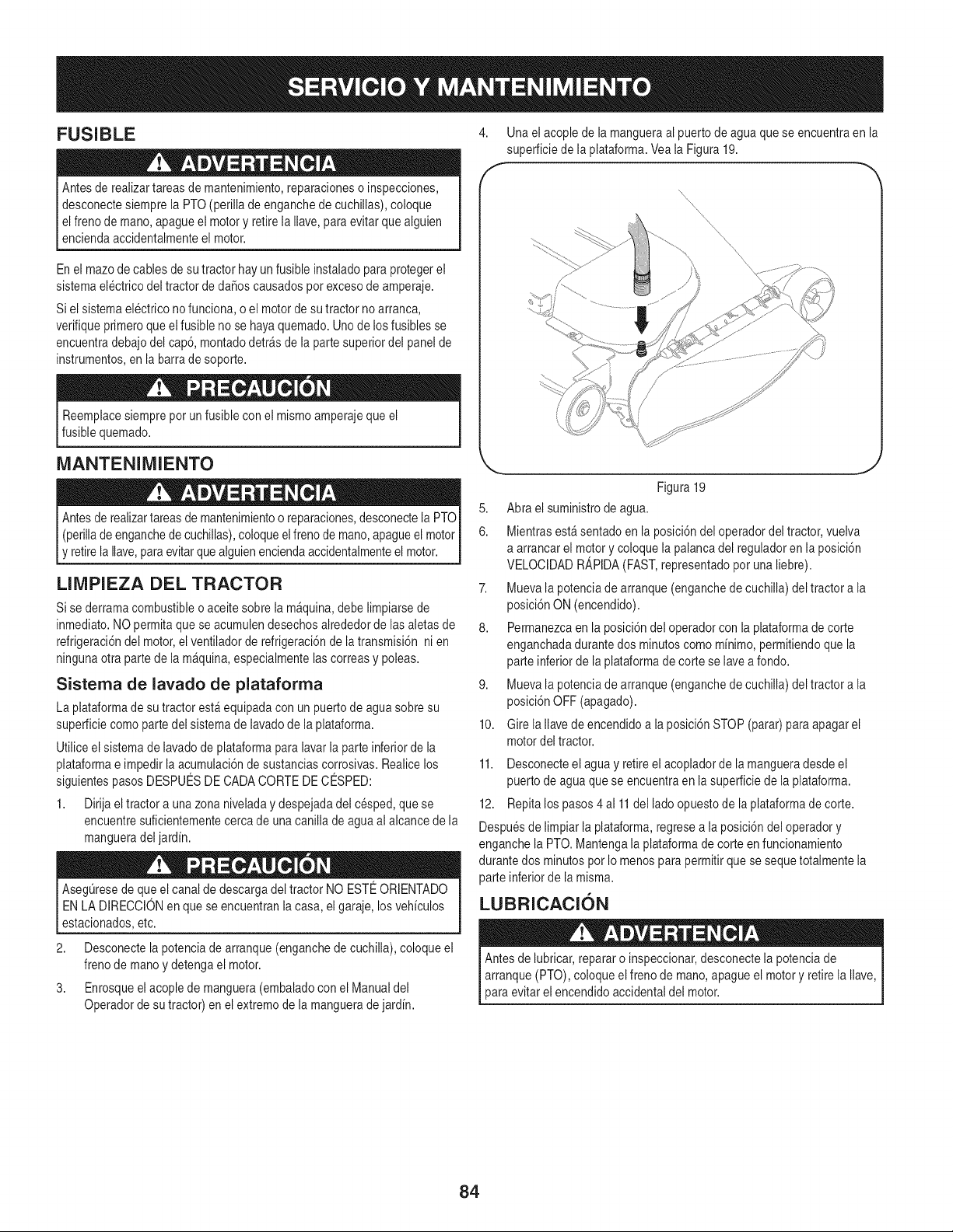
FUSIBLE
Antesde realizartareasde mantenimiento,reparacioneso inspecciones,
desconectesiemprela PTO(perillade enganchede cuchillas),coloque
elfrenode mano,apagueel motory retirela Ilave, paraevitar quealguien
enciendaaccidentalmenteel motor.
En el mazode cables de sutractor hay un fusibleinstaladopara protegerel
sistemaelectricodel tractorde daSoscausadospotexcesode amperaje.
Siel sistemaelectrico nofunciona, o el motorde su tractorno arranca,
verifiqueprimeroqueel fusible no se hayaquemado.Unode losfusibles se
encuentradebajodel cap6,montadodetr_sde la partesuperiordel panel de
instrumentos,en la barrade soporte.
Reemplacesiemprepot un fusible con el mismoamperajequeel
fusiblequemado.
4. Una el acoplede la mangueraal puertode aguaque se encuentraen la
superficiede la plataforma.Veala Figura19.
\
MANTENIMIENTO
Antesde realizartareasde mantenimientoo reparaciones,desconectela PTOI
I (perillade enganchede cuchillas),coloqueelfrenode mano,apagueel motorI
[y retirela Ilave,paraevitarquealguienenciendaaccidentalmenteel motor, j
LIMPIEZA DEL TRACTOR
Sise derramacombustibleo aceitesobre la m_quina,debe limpiarsede
inmediato.NO permitaquese acumulendesechosalrededorde las aletasde
refrigeraci6ndel motor,el ventiladorde refrigeraci6nde latransmisi6n ni en
ningunaotra partede la m&quina,especialmentelascorreasy poleas.
Sisterna de lavado de plataforrna
La plataformade su tractorest&equipadacon unpuertode aguasobre su
superficiecomo partedel sistemade lavadode la plataforma.
Utiliceel sistemade lavadode plataformapara lavarla parte inferiorde la
plataformae impedirla acumulaci6nde sustanciascorrosivas.Realicelos
siguientespasosDESPUESDE CADA CORTEDE CESPED:
1. Dirija el tractora unazonaniveladay despejadadel cesped,quese
encuentresuficientementecercade unacanilla de aguaal alcancede la
mangueradeljardin.
Aseg@esede queel canal de descargadel tractorNO ESTEORIENTADO
ENLA DIRECCIONen que se encuentranla casa, el garaje,losvehiculos
estacionados,etc.
2. Desconectela potenciadearranque (enganchede cuchilla), coloqueel
frenode manoy detengael motor.
3. Enrosqueel acoplede manguera(embaladoconel Manualdel
Operadorde su tractor)en el extremode lamanguerade jardin.
,, j
Figura19
5. Abra el suministrode agua.
6. Mientrasest&sentadoen la posici6ndel operadordel tractor,vuelva
a arrancarel motory coloquela palancadel reguladoren la posici6n
VELOCIDADR_,PIDA(FAST,representadopot unaliebre).
7. Mueva la potenciade arranque(enganchedecuchilla)del tractor a la
posici6nON (encendido).
8. Permanezcaen la posici6ndel operadorcon la plataformade corte
enganchadadurantedosminutoscomo minimo,permitiendoquela
parte inferiorde la plataformadecorte se lave a fondo.
9. Mueva la potenciade arranque(enganchedecuchilla)del tractor a la
posici6nOFF (apagado).
10. Gire laIlavede encendidoa la posici6nSTOP (parar)para apagarel
motordel tractor.
11. Desconecteel agua y retireel acopladorde la mangueradesde el
puerto de agua quese encuentraen la superficiede la plataforma.
12. Repitalos pasos4 a111del ladoopuestode la plataformade corte.
Despuesde limpiar la plataforma,regresea la posici6ndel operadory
enganchela PTO.Mantengala plataformade corte en funcionamiento
durantedos minutospot Io menospara permitirque se sequetotalmentela
parte inferiorde la misma.
LUBRICACI(SN
Antesde lubricar,repararo inspeccionar,desconectela potenciade
arranque(PTO),coloqueel frenode mano,apague el motory retire la Ilave,
para evitarel encendidoaccidentaldel motor.
84
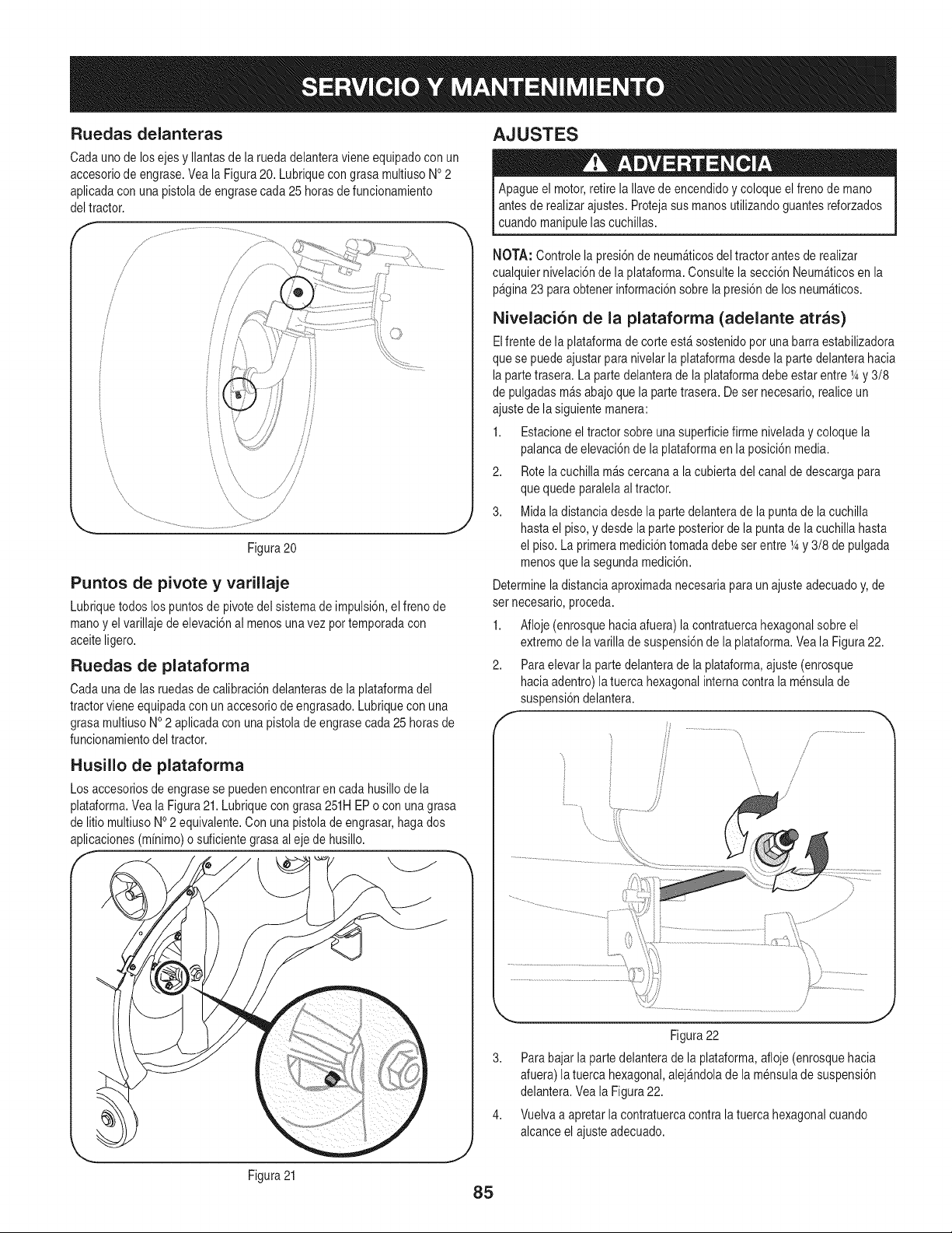
Ruedas delanteras
Cadaunode losejes y Ilantasde la ruedadelanteravieneequipadocon un
accesoriode engrase.Vea la Figura20. Lubriquecongrasa multiusoNo2
aplicadacon una pistolade engrasecada25 horasde funcionamiento
del tractor.
f ,f
/
/
/
J
/
i
\ \
Figura20
Puntos de pivote y varillaje
Lubriquetodos lospuntosde pivotedel sistemade impulsi6n,el frenode
mano y el varillaje de elevaci6nal menosunavez pottemporadacon
aceiteligero.
Ruedas de plataforma
Cadaunade lasruedasde calibraci6ndelanterasde la plataformadel
tractorvieneequipadaconun accesoriode engrasado.Lubriqueconuna
grasa multiusoNO2 aplicadacon unapistola de engrasecada25 horas de
funcionamientodel tractor.
Husillo de plataforma
Los accesoriosde engrasese puedenencontraren cada husillode la
plataforma.Vea la Figura21.Lubriquecon grasa 251HEPo con unagrasa
de litio multiusoNo2 equivalente.Con una pistolade engrasar,haga dos
aplicaciones(minimo)o suficientegrasaal eje de husillo.
f
AJUSTES
Apagueel motor,retirela Ilavede encendidoy coloqueel frenode mano
antesde realizarajustes. Protejasusmanosutilizandoguantesreforzados
cuandomanipulelas cuchillas.
NOTA: Controlela presi6nde neum_ticosdel tractor antesde realizar
cualquiernivelaci6nde la plataforma.Consultela secci6n Neum_ticosen la
pagina23 paraobtener informaci6nsobre la presi6nde los neum_ticos.
Nivelaci6n de la plataforma (adelante arras)
Elfrente de la plataformadecorte est_ sostenidopor una barraestabilizadora
que se puedeajustarpara nivelarla plataformadesde la partedelanterahacia
lapartetrasera. La partedelanteradela plataformadebeestar entre1_y 3/8
de pulgadasm&sabajo quela partetrasera. Deset necesario,realiceun
ajustede lasiguiente manera:
1. Estacioneel tractor sobre unasuperficiefirme niveladay coloquela
palancade elevaci6nde la plataformaen la posici6nmedia.
2. Rotela cuchillam&scercanaa la cubiertadel canalde descargapara
que quede }aralelaaltractor.
3. Midaladistanciadesde la partedelanterade la puntade la cuchilla
hastael piso,y desde la parteposteriorde la puntade lacuchilla hasta
el piso. La )rimeramedici6ntomadadebe set entre 1_y3/8 de pulgada
menosquela segundamedici6n.
Determinela distanciaaproximadanecesariapara unajusteadecuadoy,de
set necesario,proceda.
1. Afloje (enrosquehacia afuera)la contratuercahexagonalsobre el
extremode lavarilla de suspensi6ndela plataforma.Vea la Figura22.
2. Paraelevarla partedelanterade la plataforma,ajuste (enrosque
haciaadentro)la tuercahexagonalinternacontrala mensulade
suspensi6ndelantera.
f
fi
f ...........................
/
/
!
/
J
Figura21
85
Figura22
3. Parabajar la partedelanterade la plataforma,afloje(enrosquehacia
afuera)la tuercahexagonal,alej_ndolade la mensulade suspensi6n
delantera.Veala Figura22.
4. Vuelvaa apretarla contratuercacontra latuerca hexagonalcuando
alcanceel ajusteadecuado.
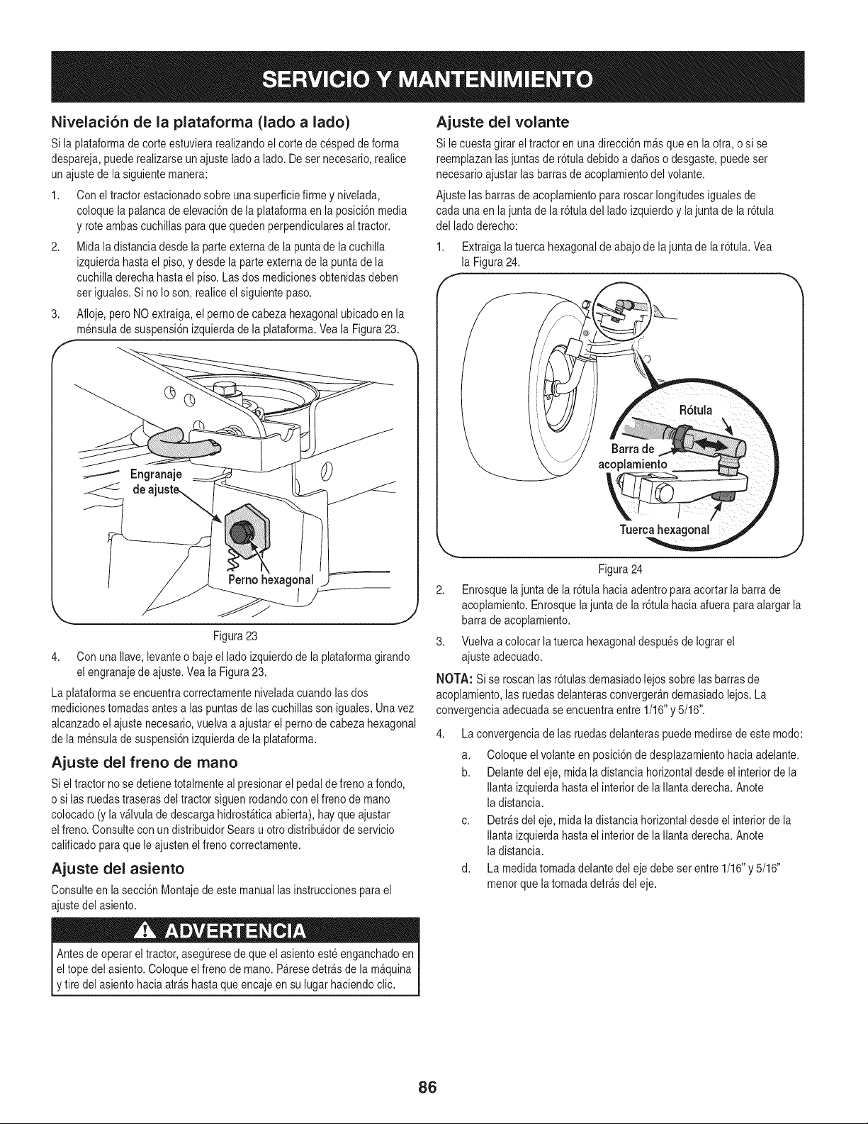
Nivelaci6n de la plataforma (lado a lado)
Si la plataformade corte estuvierarealizandoel corte de cesped de forma
despareja,puederealizarseun ajusteladoa lado. Deser necesario,realice
un ajustede lasiguientemanera:
1. Con eltractor estacionadosobre una superficiefirme y nivelada,
coloquelapalanca de elevaci6nde la plataformaen la posici6nmedia
y roteambascuchillaspara quequeden perpendicularesal tractor.
2. Midala distanciadesde la parteexternadela puntade la cuchilla
izquierdahasta el piso,y desde la parteexternade la punta de la
cuchilladerechahasta el piso.Las dos medicionesobtenidasdeben
set iguales.Si noIo son, realiceelsiguiente paso.
3. Afloje, pero NO extraiga,el pernode cabeza hexagonalubicadoen la
mensulade suspensi6nizquierdade la plataforma.Yeala Figura23.
E
Engranaje
,.. .Y
Figura23
4. Con unaIlave,levanteo bajeel ladoizquierdode la plataformagirando
el engranajede ajuste.Vea la Figura23.
La plataformase encuentracorrectamenteniveladacuandolasdos
medicionestomadasantesalas puntasde lascuchillasson iguales.Unavez
alcanzadoel ajustenecesario,vuelvaa ajustar el pernode cabeza hexagonal
de la mensulade suspensi6nizquierdade la plataforma.
Ajuste del freno de mano
Siel tractor no se detienetotalmenteal presionarel pedaldefrenoa fondo,
o si lasruedastraserasdel tractor siguenrodandocon el freno de mano
colocado(y lav&lvuladedescargahidrost&ticaabierta),hay queajustar
elfreno. Consultecon un distribuidorSears u otro distribuidorde servicio
calificadoparaque le ajustenel frenocorrectamente.
Ajuste del asiento
Consulteen la secci6n Montajedeeste manuallas instruccionespara el
ajustedel asiento.
Ajuste del volante
Si le cuestagirar el tractoren unadirecci6n m&sque en laotra, o si se
reemplazanlasjuntasde r6tuladebidoa daSoso desgaste,puedeset
necesarioajustarlasbarrasde acoplamientodel volante.
Ajustelas barrasde acoplamientopara roscarlongitudesigualesde
cada unaen lajunta de la r6tula del lado izquierdoy la juntade la r6tula
del ladoderecho:
1. Extraigala tuercahexagonalde abajode lajunta de la r6tula.Vea
la Figura24.
Figura24
2. Enrosquelajuntade la r6tula haciaadentropara acortar la barrade
acoplamiento.Enrosquela juntade la r6tulahacia afuera paraalargar la
barra de acoplamiento.
3. Vuelvaa colocar latuerca hexagonaldespuesde Iograrel
ajusteadecuado.
NOTA: Si se roscan lasr6tulas demasiadolejossobre las barrasde
acoplamiento,las ruedasdelanterasconverger_ndemasiadolejos. La
convergenciaadecuadase encuentraentre 1/16"y 5/16".
La convergenciade las ruedasdelanteraspuedemedirsede este modo:
a. Coloqueel volanteen posici6nde desplazamientohaciaadelante.
b. Delantedel eje, mida ladistancia horizontaldesdeel interiorde la
Ilanta izquierdahastael interiorde laIlantaderecha.Anote
la distancia.
c. Detr_sdel eje, midala distanciahorizontaldesde el interiorde la
Ilanta izquierdahastael interiorde laIlantaderecha.Anote
la distancia.
d. La medidatomadadelantedel eje debe set entre 1/16"y 5/16"
menorque la tomadadetr_sdel eje.
,tire del asientohaciaarras hastaque encajeen su lugar haciendoclic.
86
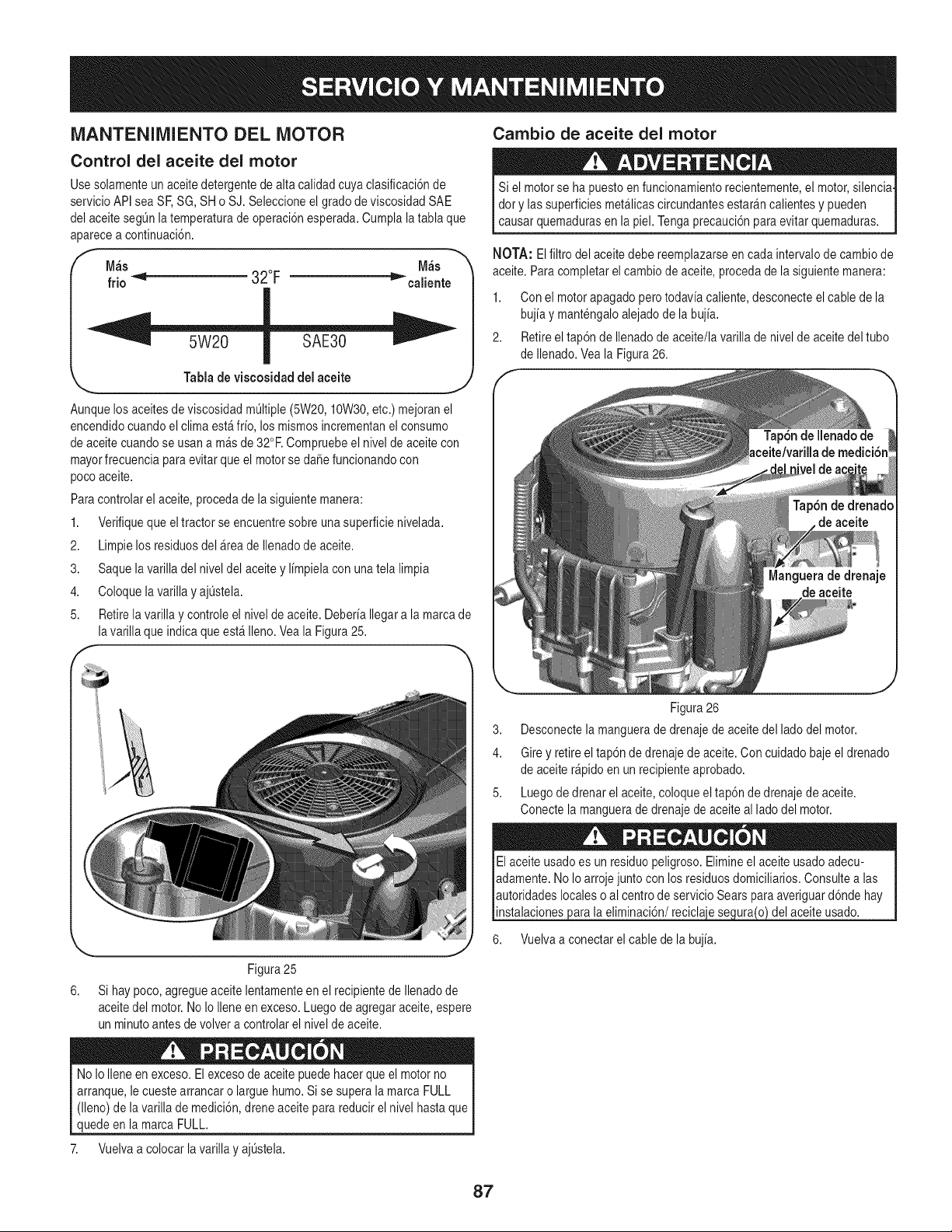
iVlANTENIIVllENTO DEL MOTOR
Control del aceite del motor
Usesolamenteun aceitedetergentede alta calidadcuya clasificaci6nde
servicioAPIsea SF,SG, SH o SJ. Seleccioneel grado de viscosidadSAE
del aceitesegQnlatemperaturade operaci6nesperada.Cumplalatabla que
aparecea continuaci6n.
M_s M_s
frio _ 32°F "l_caliente
Tablade viscosidaddel aceite
J
Aunquelosaceitesde viscosidadmL]ltiple(5W20,10W30,etc.) mejoranel
encendidocuandoel clima est_ frio, los mismosincrementanel consumo
de aceitecuandose usana m&sde 32°R Compruebeel nivel de aceitecon
mayorfrecuenciaparaevitarque el motorse daSefuncionandocon
pocoaceite.
Paracontrolarel aceite,procedade lasiguientemanera:
1. Verifiqueque eltractor se encuentresobre unasuperficienivelada.
2. Limpielos residuosdel _rea de Ilenadode aceite.
3. Saque lavarilla del niveldel aceite y limpielacon unatela limpia
4. Coloquela varillay ajL]stela.
5. Retirelavarilla y controleel nivelde aceite. DeberiaIlegara la marcade
lavarilla que indica queest_ Ileno.Veala Figura25.
Figura25
6. Si hay poco,agregueaceitelentamenteen el recipientede Ilenadode
aceitedel motor.No IoIleneen exceso.Luegode agregaraceite,espere
un minutoantes de volvera controlarel nivelde aceite.
Cambio de aceite del motor
Si el motorse ha puestoen funcionamientorecientemente,el motor,silencia
dory lassuperficiesmet&licascircundantesestar_ncalientesy pueden
causar quemadurasen la piel.Tengaprecauci6nparaevitarquemaduras.
NOTA: Elfiltro del aceitedebe reemplazarseen cada intervalode cambiode
aceite. Paracompletarel cambiode aceite,procedade lasiguientemanera:
1. Con el motorapagadopero todavia caliente,desconecteel cable de la
bujiay mantengaloalejado de la bujia.
2. Retireel tap6n de Ilenadode aceite/lavarillade nivelde aceite deltubo
de Ilenado.Veala Figura26.
Figura26
3. Desconectela manguerade drenajede aceitedel lado del motor.
4. Girey retire el tap6nde drenajede aceite.Con cuidadobaje el drenado
de aceiter_pidoen un recipienteaprobado.
5. Luegode drenar el aceite,coloqueel tap6n de drenajede aceite.
Conecte lamanguerade drenajede aceiteal lado del motor.
instalaciones}arala eliminaci6n/recicla
6. Vuelvaa conectarel cablede la bujia.
del aceiteusado.
No Io Ileneen exceso.El excesode aceite puedehacerqueel motorno
arranque,lecuestearrancaro largue humo.Si se superala marca FULL
(lleno)de lavarilla de medici6n,dreneaceiteparareducirel nivel hastaque
quedeen la marca FULL.
7. Vuelvaa colocarla varillay ajL]stela.
87
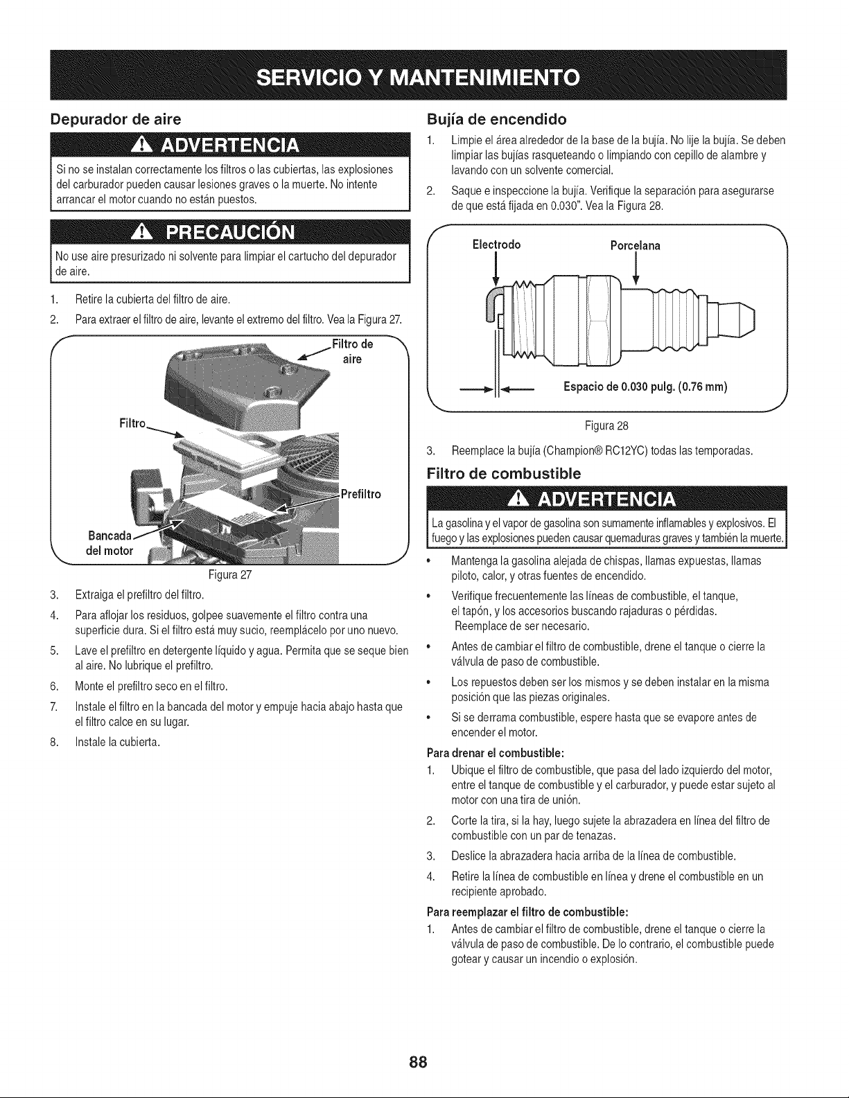
Depurador de aire
Si no se instalancorrectamentelosfiltros o las cubiertas,lasexplosiones
del carburadorpuedencausarlesionesgraveso lamuerte.No intente
arrancarel motorcuandono est_n puestos.
Nouse aire presurizadoni solventepara limpiarel cartuchodel depurador
de aire.
1,
2.
Retirela cubiertadel filtro de aire.
Paraextraerelfiltro de aire,levanteel extremodel filtro.Veala Figura27.
,=_.....fFiltrode "_
aire
dei motor
Figura27
3. Extraigael prefiltrodelfiltro.
4. Para aflojarlos residuos,golpee suavementeel filtrocontrauna
superficiedura. Si el filtroest_ muysucio,reempl_celopotuno nuevo.
5. Laveel prefiltroen detergenteliquidoy agua.Permitaque se sequebien
al aire.No lubriqueel prefiltro.
6. Monte el prefiltroseco en elfiltro.
7. instale el filtroen labancadadel motory empujehacia abajohastaque
elfiltro calce en su lugar.
8. instale la cubierta.
Bujia de encendido
1. Limpieel _rea alrededorde labasede la bujia. No lije la bujia.Se deben
limpiar lasbujias rasqueteandoo limpiandocon cepillode alambrey
lavandocon unsolventecomercial.
f
Saquee inspeccionela bujia.Verifiquelaseparaci6nparaasegurarse
de queest_fijada en 0.030".Veala Figura28.
2,
Eiectrodo
===_
Porceiana
!
_=== Espaciode 0.030pulg. (0.76ram)
Figura28
3. Reemplacelabujia (Champion@RC12YC)todas lastemporadas.
Filtro de combustible
La gasolinay elvaporde gasolinasonsumamenteinflamablesy explosivos.El
fuegoylasexplosionespuedencausarquemadurasgravesy tambienlamuerte.
,, Mantengalagasolina alejadadechispas,llamas expuestas,llamas
piloto,calor,y otrasfuentesde encendido.
,, Verifiquefrecuentementelaslineas de combustible,eltanque,
el tap6n,y losaccesoriosbuscandorajaduraso p@didas.
Reemplacede set necesario.
,, Antesde cambiarel filtro de combustible,drene eltanqueo cierre la
v_lvula de pasode combustible.
,, Los repuestosdebenset losmismosy se debeninstalaren lamisma
posici6nque laspiezas originales.
,, Si se derramacombustible,esperehastaque se evaporeantesde
encenderel motor.
Paradrenar el combustible:
1. Ubiqueel filtrode combustible,que pasadel ladoizquierdodel motor,
entreel tanquede combustibley el carburador,y puedeestar sujetoal
motorcon unatira deuni6n.
2. Corte la tira,si la hay,luegosujetela abrazaderaen linea del filtro de
combustibleconun par de tenazas.
3. Deslice la abrazaderahaciaarribade la linea de combustible.
4. Retirelalinea de combustibleen linea y dreneel combustibleen un
recipienteaprobado.
Parareempiazar el filtro de combustible:
1. Antesde cambiarel filtro de combustible,drene eltanqueo cierre la
v_lvula de pasode combustible.De Iocontrario,elcombustiblepuede
goteary causar un incendioo explosi6n.
88
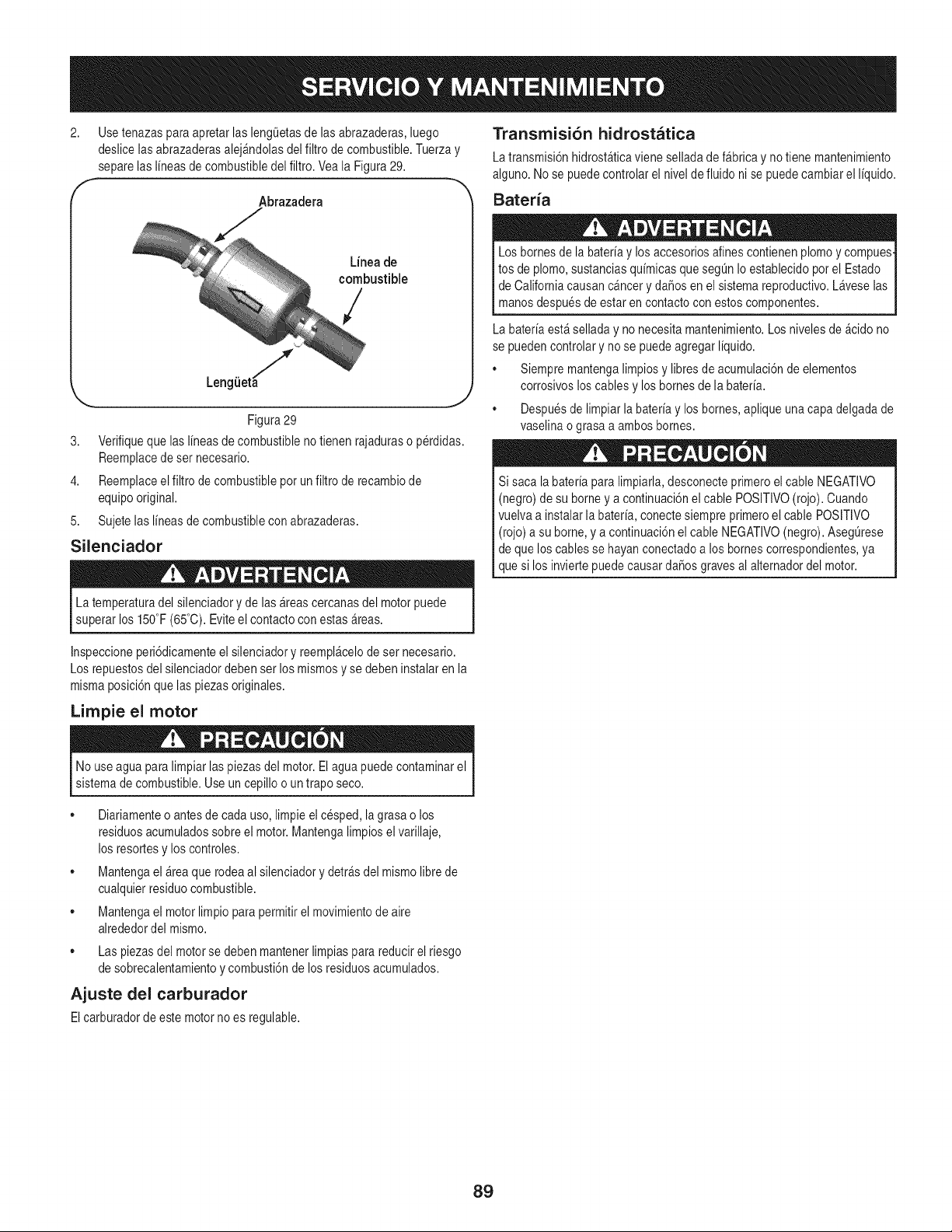
2. Use tenazas paraapretarlas lengQetasde lasabrazaderas,luego
deslice lasabrazaderasalej_ndolasdel filtro de combustible.Tuerzay
separelas I[neasde combustibledel filtro.Veala Figura29.
f Abrazadera h
L[neade
combustible
/
LengiJet!
J
Figura29
3. Verifiqueque lasI[neasdecombustibleno tienen rajaduraso perdidas.
Reemplacede ser necesario.
4. Reemplaceelfiltro de combustiblepot un filtrode recambiode
equipooriginal.
5. Sujetelas I[neasde combustiblecon abrazaderas.
Silenciador
La temperaturadel silenciadory de las_reas cercanasdel motorpuede
superarlos 150°F(65°C).Eviteel contactocon estas areas.
Transrnisi6n hidrostatica
Latransmisi6nhidrost_ticavieneselladade f_brica y notiene mantenimiento
alguno.Nose puedecontrolarel nivelde fluidoni se puedecambiarel I[quido.
Bateria
Los bornesde la bater[ay los accesoriosalines contienenplomoy compues
tos de plomo,sustanciasqu[micasquesegOnIoestablecidoporel Estado
I de Californiacausancancer y daSosen el sistemareproductivo.Laveselas
[ manos despuesde estar en contactocon estos componentes.
La bater[aest&selladay no necesitamantenimiento.Los niveles de _cidono
se puedencontrolary no se puedeagregar I[quido.
• Siempre mantengalimpiosy libresde acumulaci6nde elementos
corrosivosloscablesy los bornesde la bater[a.
• Despuesde limpiarlabater[ay los homes,apliqueuna capadelgadade
vaselinao grasa a ambos bornes.
Si saca la bater[aparalimpiarla,desconecteprimeroel cable NEGATIVO
(negro) de su borney a continuaci6nel cable POSlTIVO(rojo). Cuando
vuelvaa instalarla hater[a,conectesiempreprimeroel cable POSITIVO
(rojo) a su borne,y a continuaci6nel cable NEGATIVO(negro). AsegOrese
de que los cablesse hayan conectadoa los bornescorrespondientes,ya
que si los inviertepuedecausardaSosgravesal alternadordel motor.
Inspeccioneperi6dicamenteel silenciadory reempl&celode sernecesario.
Los repuestosdel silenciadordebenser losmismosy se deben instalaren la
mismaposici6nquelas piezasoriginales.
Lirnpie el motor
Nouse agua para limpiarlas piezasdel motor.El agua puedecontaminarel
sistema de combustible.Use un cepilloo un trapo seco.
• Diariamenteo antes de cada uso,limpieel cesped, lagrasao los
residuosacumuladossobreel motor.Mantengalimpiosel varillaje,
los resortesy loscontroles.
• Mantengael _rea que rodeaal silenciadorydetr_sdel mismolibrede
cualquierresiduocombustible.
• Mantengael motorlimpio para permitirel movimientode aire
alrededordel mismo.
• Las piezasdel motorse debenmantenerlimpias para reducirel riesgo
de sobrecalentamientoy combusti6nde losresiduosacumulados.
Ajuste del carburador
Elcarburadorde este motorno es regulable.
89
Nuncaalmacenelatractor corta cespedcon combustibleen el tanque
en unespaciocerrado o en &teaspocoventiladasdondelos gasesdel
combustiblepuedanIlegara unallama expuesta,unachispao un piloto
como el quetienen algunoshornos,calentadoresde agua,secadoresde
ropao algQnartefactoa gas.
PREPARACION DEL MOTOR
IMPORTANTE: Elcombustiblequequedaen el tanquecuandohacecalor
se deterioray causaproblemasgravesde encendido.
Paraevitar quese formendep6sitosde goma dentrodel carburadordel motor
y posiblesdesperfectosen el motor,elsistemade combustibledebe set
vaciadocompletamente,o se debetratar lagasolinacon un estabilizadorpara
evitarel deterioro.
PREPARACI6N DEL TRACTOR CORTA ClaSPED
• Limpiey lubriqueperfectamenteeltractor comose describeen las
instruccionesdelubricaci6n.
• No utiliceuna lavadoraa presi6no manguerade jardfnpara limpiarsu
unidad.
• Almacenela unidad en unazona limpiay seca.No la almacenecerca de
productoscorrosivoscomo pot ejemplofertilizantes.
Si utilizaun estabilizadorde combustible:
a. Lea las instruccionesy recomendacionesdel fabricantedel
producto.
b. Agreguela cantidadcorrectade estabilizadorpara lacapacidad
del sistemade combustiblea gasolinalimpiay nueva.
c. Lleneel tanquecon combustibletratado y hagafuncionarel motor
2-3 minutospara estabilizarel combustibledentrodel carburador.
Cuandovacfeel sistemade combustible:
a. No drene elcombustiblecuandoel motorest&caliente.Permita
queel motorse enfrfebien. Dreneel combustibledentrode un
recipienteaprobadoy al aire libre,lejosde cualquier
llamaexpuesta.
b. Dreneun granvolumende combustibledel tanque,desconectando
la Ifneadecombustibledel filtro decombustibleen Ifneaquese
encuentracerca del motor.VeaParadrenarel combustibleen
la p&gina26.
La gasolina essumamenteinflamabley puedeset explosivaen ciertas
condiciones.Vacfelaantes de almacenarel equipoduranteperfodos
prolongados.Dreneel combustibleQnicamentedentrode unrecipiente
aprobadoy alaire libre,lejos de cualquierllamaexpuesta.Dejeque el mo-
tor se enfrfe.Antesde drenarel combustible,apaguecigarrillos,cigarros,
pipasy otrasfuentesde combusti6n.Almacenelagasolinaen un recipiente
aprobado,en un lugarseguro.
c. Vuelvaa conectarla Ifneade combustibley hagafuncionar el
motorhastaque comiencea fallar, useentoncesel cebadorpara
mantenerel motoren marchahastaagotartodo el combustible
del carburador.
d. Desconectela Ifneadecombustibley drenela gasolinaque queda
en el sistema.
La gasolinaes unasustanciat6xica.Eliminela gasolinaadecuadamente.
Comunfquesecon lasautoridadeslocalesparaaveriguarcuries son los
metodosadecuadospara eliminarla gasolina.
Extraigala bujfay vierta una (1)onza de aceitepara motorpor el orificio de
la bujfahaciael interiordel cilindro.Hagagirar el motorvariasveces para
distribuirel aceite.Vuelvaa colocar la bujfa.
9O
Antesde realizarcualquiertipo de mantenimientoo servicio,desenganche
todos loscontrolesy detengael motor.Esperea que se detengancompleta-
mentetodas laspiezasm6viles.Desconecteel cablede la bujia y p6ngalo
haciendomasacontrael motorparaevitarque se enciendaaccidental-
mente.Utilice siempreanteojosde seguridadduranteelfuncionamientoo
mientrasajustao reparaeste equipo.
En esta secci6n se analizan problemas menores de servicio. Para ubicar el Centro de Servicio Sears m_s eercano o para programarun servicio,
simplementeeomuniquesecon Searsal tel_fono 1-800-4-MY-HOME®.
El motorno arranca
El motorfuncionade
maneraerrHtica
El motorrecalienta
1. Palancadeenganchede cuchillaconectada.
2. No estHcolocado elfreno de mano.
3. Se ha desconectadoel cablede la bujia.
4. La palanca de control del regulador/cebadorno
estHen laposici6nde arranquecorrecta.
5. El tanquede combustibleestHvacio o el
combustiblese ha echadoa perder.
6. La linea del combustibleestHbloqueada.
7. Labujia no funcionacorrectamente.
8. Motorahogado.
1,
2.
3.
4.
5.
6.
Launidad estHfuncionandocon el
cebadoractivado.
Los cablesde la bujia estHnflojos.
La linea del combustibleestHtapadao el
combustiblese ha echadoa perder.
La ventilaci6nde la tapadel combustible
estHobstruida.
Hayaguao suciedaden el sistemade
combustible.
Eldepuradorde aireestHsucio.
1. El nivelde aceitedel motorestHbajo
2. Flujodeairerestringido
El motorvacila a altas 1. Pocaseparaci6nde los electrodosde la bujia 1.
revoluciones
1. Coloquela palancaen posici6nde apagado(OFF).
2. Coloqueelfreno de mano.
3. Conecteelcable a la bujia.
4. Coloquela palancadel regulador/cebadoren la posici6n
FAST(r@ido).
5. Lleneel tanquecon gasolinalimpia y nueva
(de menosde 30 dias).
6. Limpiela linea de combustibley reemplaceel filtrode
combustible.Veala secci6nde Servicioy Mantenimiento.
7. Limpieo cambiela bujia o ajustela separaci6n.
8. Arranqueel motorcon el reguladoren posici6nFAST
(velocidadr@ida).
1. Muevala palancadel regulador/cebadorparasacarlode
la posici6nde cebador.
2. Conecteyajuste loscablesde la bujia.
3. Limpiela linea de combustible;Ileneeltanque con gaso-
linalimpia y nuevay reemplaceelfiltro decombustible.
4. Destapelaventilaci6no reemplacelatapa si estHda_ada.
5. Vacieel tanquedecombustible.Lleneel tanquecon
gasolinalimpiay nueva.
6. Reemplaceelelementode papeldel depuradorde aireo
limpieel prefiltrode espuma.
1. Lleneel motorcon la cantidady tipo de aceiteadecuado.
2. Eliminelos recortesde cespedy losdesechosde
alrededorde lasaletasde enfriamientodel motory de la
carcasadel soplador.
Extraigalabujia y regulela separaci6n.
91
Elmotorfuncionarealen
marchalenta
Vibraci6nexcesiva
La cortadorade c_spedno
procesalos recortescomoabono
Cortedesigual
1,
2.
1.
2.
1.
La buj[ade encendidoesta sucia
Eldepuradorde aireesta sucio
Las cuchillasdecorte estanflojas o
desbalanceadas
La cuchillade corteesta da_ada,
desafiladao doblada
La velocidaddel motores demasiadolenta.
2. Pastomojado.
3. C_speddemas[adoalto.
4. Cuchilladesafilada.
1. La plataformano esta correctamentenivelada.
2. Cuchilladesafilada.
3. Presi6nde neumaticosdesigual.
1. Extraigala buj[ay regulela separaci6n.
2. Reemplaceelelementodepuradorde airey/o limpie
el prefiltro.
1. Apriete lacuchillay el husillo. Estabilicela cuchilla.
2. Reemplacelacuchilla.
1. Coloque el controldel estrangulador/cebadorenla
posici6nFAST(velocidadrapida,representadapot
unaliebre).
2. Noproceseabonocuandoel pastoestamojado.
3. Corte unavez con altura de corte elevaday luegovuelva
a cortarel c_speda la alturadeseada,o hagauna pasada
de corte m_.sangosta.
4. Afile ocambie lacuchilla.
1. Haga un ajustede la plataformade ladoa lado.
2. Afile ocambie la cuchilla.
3. Verifiquela presi6nde los cuatroneumaticos.
o Este y los manualesde todos sus otros productoslos encontrar_en linea.
o Suspreguntasser_nrespondidaspor nuestro equipode especialistas.
o Obtengaun plan de mantenimientopersonalizadopara su hogar.
o Encuentreinformaci6ny herramientasquelo ayudar_ncon los proyectosdom#sticos.
maHage home
presestadopos Seass
92
Felicitacionespor haberrealizadounaadquisici6ninteligente.El
productoCraftsman@queha adquiridoest_ dise_adoy fabricado
parabrindarrnuchosa_osde funcionarnientoconfiable.Perocorno
todoslos productosa vecespuederequerirde reparaciones.Esen
esernornentocuandoel disponerde unAcuerdode protecci6npara
reparacionesle puedeahorrardineroy problernas.
A continuaci6nsedetallanlos puntosincluidosenel Acuerdo:
• Servicio experto prestadopor nuestros10,000especialistasen
reparacionesprofesionales
• Servicio ilirnitadosin cargoparalaspiezasy la rnanodeobraen
todaslas reparacionescubiertas
• Reernplazodel productohasta 1500d61aressi no es posible
repararel productocubierto
• Descuentode 10%del precionormaldel servicioy delas piezas
relacionadascon el rnisrnoqueno est_ncubiertasporel acuerdo;
adern&s,10%del precionormalde la verificaci6nde rnantenirniento
preventivo
• Ayudar_pida pottel_fono- IoIlarnarnosResoluci6nR_pida- el
apoyotelef6nicode un Charnuscaal representante.Pienseen
nosotroscornoel manual"de undue_ohablador."
Unavezadquiridoel Acuerdo,puedeprograrnarel serviciocon
tan s61orealizarunaIlarnadatelef6nica.PuedeIlarnaren cualquier
mornentodeldia o dela nocheo prograrnarun servicioen linea.
ElAcuerdode Protecci6nde Reparaci6nes una cornprasin riesgo.
Siustedanula poralguna raz6nduranteel periodode garantiade
producto,proporcionarernosun reernbolsoIleno.O,un reernbolso
prorrateadoencualquiermornentodespu_sdelperiodode garantia
de productoexpira, iAdquieraboysu acuerdode protecci6npara
reparaciones!
Seaplican deterrninadaslirnitaciones y exclusiones.Paraobtener
inforrnaci6nadicional y preciosen los Estados UnidosIlarne al
1-800-827-6655.
El*Coverage en Canad_variaen algunosarticulos. Paradetalles
Ilenosla IlarnadaCharnuscaCanad_en 1-800-361-6665.
Servicio de instalaci6nde Sears
Sideseasolicitarla instalaci6nprofesionalde Searsde aparatos
dorn_sticos,dispositivosparaabrirportones,calentadoresde agua
y otrosarficulosdorn_sticosirnportantes,en los EstadosUnidoso
Canad_Ilarneal 1-800-4-MY-HOME®.
93
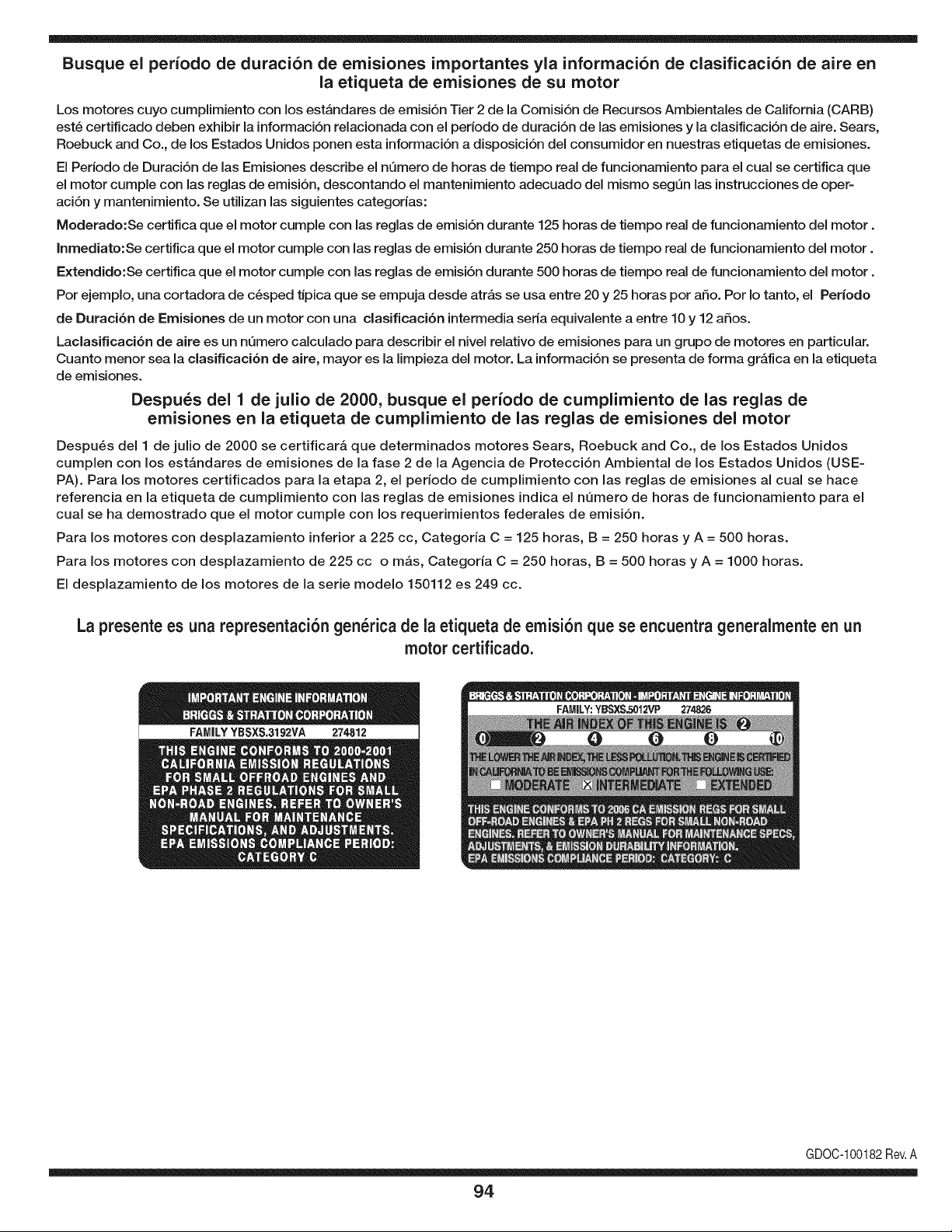
Busque el periodo de duraci6n de emisiones importantes yla informaci6n de clasificaci6n de aire en
la etiqueta de emisiones de su motor
Los motores cuyo cumpiimiento con los estAndares de emisi6n Tier 2 de la Comisi6n de Recursos Ambientales de California (CARB)
est6 certificado deben exhibir la informaci6n relacionada con el perJodo de duraci6n de las emisiones y la clasificaci6n de aire. Sears,
Roebuck and Co., de los Estados Unidos ponen esta informaci6n a disposici6n deJ consumidor en nuestras etiquetas de emisiones.
El Periodo de Duraci6n de las Emisiones describe el nQmero de horas de tiempo real de funcionamiento para el cual se certifica que
el motor cumple con las reglas de emisi6n, descontando el mantenimiento adecuado deJmismo segQn las instrucciones de oper-
aci6n y mantenimiento. Se utilizan las siguientes categorias:
Moderado:Se certifica que el motor cumpie con las reglas de emisi6n durante 125 horas de tiempo real de funcionamiento deJ motor.
Inmediato:Se certifica que el motor cumple con las reglas de emisi6n durante 250 horas de tiempo real de funcionamiento deJ motor.
Extendido:Se certifica que el motor cumple con las reglas de emisi6n durante 500 horas de tiempo real de funcionamiento deJ motor.
Por ejemplo, una cortadora de c6sped tJpica que se empuja desde atrAs se usa entre 20 y 25 horas por afio. Por Io tanto, el Periodo
de Duraci6n de Emisiones de un motor con una clasificaci6n intermedia seria equivalente a entre 10 y 12 afios.
Laclasificaci6n de aJre es un nQmero calculado para describir eJnivel reiativo de emisiones para un grupo de motores en particular.
Cuanto menor sea Jaclasificaci6n de aire, mayor es JaJimpieza deJ motor. La informaci6n se presenta de forma gr&fica en Jaetiqueta
de emisiones.
Despu_s del 1 de julio de 2000, busque el periodo de cumplimiento de las reglas de
emisiones en la etiqueta de cumplimiento de las reglas de emisiones del motor
Despu_s deJ 1 de julio de 2000 se certificar_, que determinados motores Sears, Roebuck and Co., de los Estados Unidos
cumpien con los estAndares de emisiones de la fase 2 de la Agencia de Protecci6n Ambiental de los Estados Unidos (USE-
PA). Para los motores certificados para la etapa 2, el periodo de cumpiimiento con las reglas de emisiones al cual se hace
referencia en la etiqueta de cumpiimiento con las reglas de emisiones indica el nQmero de horas de funcionamiento para el
cuaJ se ha demostrado que el motor cumpie con los requerimientos federales de emisi6n.
Para los motores con desplazamiento inferior a 225 cc, Categoria C = 125 horas, B = 250 horas y A = 500 horas.
Para los motores con desplazamiento de 225 cc o mAs, Categoria C = 250 horas, B = 500 horas y A = 1000 horas.
El despiazamiento de los motores de la serie modelo 150112 es 249 cc.
La presente es una representaci6n gen_rica de la etiqueta de emisi6n que se encuentra generaimente en un
motor certificado.
GDOC-100182Rev.A
94
(Esta p_.ginase aplica s61oen EE.UU. y Canada.).
Sears, Roebuck and Co., U.S.A. (Sears), el Consejo de Recursos Arnbientales de California (CARB)
y la Agencia de Protecci6n Arnbiental de los Estados Unidos (EPA)
Declaraci6n de garantia del sistema de control de emisiones (derechos y obligaciones de la garantia de defectos del propi=
etario)
LA COBERTURADE LA GARANTJADE CONTROLDE EMISIONESES Y PARALOSMODELOSCERTIFICADOSDELANO 1997YPOSTERIORES,
APLIOABLEA LOS MOTORESCERTIFICADOSCOMPRADOSENCALIFOR- QUESE COMPRENY UTILICENENCUALQUIERPARTEDE LOS ESTADOS
NIA EN1995Y POSTERIORMENTE,QUESE UTILIZANENCALIFORNIA, UNIDOS(Y A PARTIRDEL 1 DE ENERODE2001 EN CANADA).
Declaraci6n de garanfia sobre defectos en el control de ernJsiones para California y los Estados UnJdos
ElConsejode RecursosAmbientalesde California(CARB),la EPA(Agencia
de Protecci6nAmbientalde los EE.UU.)y Searstienenel gusto de explicarla
garantiadel sistemade control de emisionespara motoresdela_o 2000y para
elfuturo con relaci6na motorespeque_ostodo terreno(SORE).En California,
los nuevosmotorespeque_ostodo terrenodebenestar dise_ados,construidos
y equipadosparacumplirconlas rigurosasnormasanti-smogdelestado.En
el restodelos EstadosUnidos,losmotoresnuevostodoterrenode encendido
porchispacertificadosparael a_o 1997debencumplirest_ndaressimilares
establecidospot la EPA.Sears debegarantizarel sistemade control de emi-
sionesde su motorparalosperiodosde tiempoenumeradosa continuaci6n,
siemprequeno hayaabuso,negligenciao mantenimientoindebidode su
motortodoterrenopeque_o.Su sistemade controlde emisionespuedeincluir
piezastalescomoel carburador,el filtrode aire, elsistemade encendido,el
silenciadoryel conversorcatalitico.Tambienpuedeincluirconectoresy otras
unidadesrelacionadascon lasemisiones.Dondeexistaunacondici6ncubierta
por la garantia,Searsreparar_su peque6omotortodo terrenosin costo alguno
incluyendodiagn6stico,piezasy manode obra
Cobertura de la garantJa Sears para defectos en el control de ernJsiones
Los motorestodo terrenopeque6osest_ngarantizadosen Io relativoalcontrol alas disposicionesque se indiquena continuaci6n.Si una partede su motor
de emisionesparadefectosen piezasduranteun per[odode dos a_os,sujeto cubiertapot lagaranfiaes defectuosa,Sears reparar_o sustituir_dichaparte.
Responsabilidades del propietario en relacibn con la garantia
Comopropietariodel motortodo terrenopeque_o,Ud.es responsablede la
realizaci6ndel mantenimientorequeridoquese incluyeen las instrucciones
de operaci6ny mantenimiento.Searsrecomiendaquese conserventodoslos
recibosrelativosal mantenimientode su motortodoterrenopeque_o,pero
no pude denegarla garantiasimplementepor la faltade los mismos,o por su
incumplimientodel mantenimientoprogramatic.Comopropietariodel motor
peque_otodoterrenodebe saberque, sin embargo,Searslepuedenegar
lacoberturade lagarantiasi su motortodoterrenopeque6oouna piezadel
mismohanfalladodebido a abuso,negligencia,mantenimientoindebidoo
a modificacionesnoaprobadas.Ud.es responsablede presentarsu motor
todoterrenopeque6oa un distribuidorde serviciosSearsautorizadotan pronto
comoaparezcaun problema.Las reparacionesde la garantiasinconflicto
debencompletarseen unplazode tiemporazonable,no superiora 30 dias.Si
tienealguna preguntarespectoa sus derechosy responsabilidadesreferentes
a lagarantia,debe contactarcon un representantede serviciosSearsal 1--
800--469--4663.La garantiade emisioneses unagarantiapordefectos.Los
defectosse juzgande acuerdocon elfuncionamientonormalde un motor.La
garantiano est_relacionadacon unapruebade emisionesen uso.
Disposiciones de la garantJa Sears para defectos en el control de emJsiones
Las siguientesson disposicionesespecificasrelacionadascon la coberturade lagarantia paradefectosenel controlde emisiones.Esun a_adidoa lagarantiade
motorSearspara motoresno reguladosque seencuentraen lasinstruccionesde funcionamientoy mantenimiento.
1. Piezascon garantia
La coberturade esta garantiase extiendeL]nicamentealas piezas
queaparecena continuaci6n(las partesde lossistemasde control de
emisiones),siempreque dichas piezasestuvieranya en el motoren el
momentode su compra.
a. Sistemademedici6n de combustible
• Sistema de enriquecimientopara arranqueen frio
• Carburadory partesinternas
• Bombade combustible
b. Sistemadeinducci6nde aire
• Filtrode aire
• Colector de admisi6n
c. Sistemadeencendido
• Bujia(s)de encendido
• Sistema de encendidomagneto
d. Sistemadelcatalizador
• Convertidorcatalitico
• Colector de escape
• Sistema de inyecci6nde aireo v_lvulade impulsos
e. Elementosvariadosusadosenlos sistemasanteriores
• Wlvulas de vacio,sensiblesa temperatura,posici6ny tiempo
e interruptores
• Conectoresy montajes
2. AIcancede la cobertura
Searsgarantizaal poseedorinicialy a loscompradoressubsiguientes
quelas piezascon garantiano tendr_ndefectosen materialesni mano
de obraque provoquenla falla de las mismasduranteun periodode
dos aSosa partirde la fechaen queel motorse entregaa un comprador
particular.
3. Sin cargo
La reparaci6no reemplazode cualquierpartecon garantia se realizar_
sin cargo algunoparael poseedor,incluyendotareasde diagn6sticoque
permitandeterminarsi una partecon garantiaes defectuosa,siempreque
dichodiagn6sticose realiceen un distribuidor de serviciosSearsautoriza-
do. Parael servicio de lagarantia de emisiones,contacteal distribuidorde
serviciosSearsautorizadom_scercanoincluidoen las"P_ginasamarillas"
en lascategorias"Motores,gasolina","Motoresde gasolina","Podadoras
de cesped",o similares.
4. Reclamacionesy exclusionesa la cobertura
Las reclamacionesde lagarantia debenenviarsede acuerdocon las
disposicionesde la politica de garantia paramotoresSears.La cobertura
de lagarantia excluir_defectosen piezascongarantia queno sean partes
originalesSears,o abuso,negligenciao mantenimientoincorrecto,tal y
como se estableceen lapolitica de garantia para motoresSears.Sears no
es responsablede lasfallas en piezas con garantia provocadaspor el uso
de partesa_adidas,que no seanoriginaleso quese hayan modificado.
5. Mantenimiento
Cualquierpartecon garantiaque no esteprogramadaparaset reempla-
zadacomo mantenimientorequerido,o que s61odeba inspeccionarse
regularmentealefecto de "inspeccioneo reemplacesegL]nsea necesario",
estar_garantizadacontradefectosduranteel periodode la garantia.Todas
las piezasgarantizadasqueesten programadaspara su reemplazopara
cumplir con los requisitosde mantenimientoestar_ngarantizadass61o
por el periodoanterioral primerreemplazoprogramaticparadicha pieza.
Cualquierpiezade recambioquesea equivalenteenfuncionamientoy
durabilidadpuedeusarse para realizarmantenimientoo reparaciones.El
propietarioes responsablede realizartodoel mantenimientorequerido,tal
y comose define en las instruccionesde funcionamientoy mantenimiento
Sears
6. Coberturaindirecta
Porla presente,la coberturase extiendea la falla de cualquiercomponente
de motorprovocadapot lafalla de unapieza con garantiaque este todavia
en periodode garantia.
En los EstadosUnidosy Canad_hay unalinea de atenci6nde 24 horas,1-800-469--4GG3,quecuentacon unmenL]con mensajespre-grabadosque contienen
informaci6npara el mantenimientode motores.
DECLARACIONFEDERALy/oDECALIFORNIASOBRE GARANTJAS EN EL CONTROL DE EIVIISIONES
SUS DERECHOS Y OBLIGACIONES EN CUANTO A LA GARANTJA
MTDConsumerGroupInc, laAgencia de Protecci6nMedioambientalde los EstadosUnidos(EPA),y paraaquellosproductoscertificadosparasu ventaen el es-
tadode California,el Departamentode los Recursosdel Aire de California(CARB)secomplacenenexplicarla garanfiaque cubre al sistemade control (ECS)de
emisiones(evaporativasy/o de escape)de su equipoy motor(motorde equiposde exteriores)deencendidopot chispaparatodo terreno,peque_o,de exteriores
del a_o2006 y a_osposterioresEn California,losnuevosmotoresdeequipos de exterioresdebenestar dise_ados,construidosy equipadospara cumplircon las
estrictasnormasantipoluci6ndel Estado(en otrosestados,losequipos del a_o 1997y modelosposterioresdebenser estar dise_ados,construidosy equipados
para cumplircon las regulacionesdemotoresdeencendidopor chispa paratodoterrenopeque_osde laAgencia de Protecci6nMedioambientalde los Estados
Unidos,(EPA).MTDConsumerGroupInc. debe garantizarel sistemade control de emisiones(ECS) de su motorde equipos de exteriorespot el periodode
tiempo indicadom_sabajo,siemprey cuando no existausoincorrecto,negligenciao mantenimientoinadecuadodedicho motor.
Su ECSpuedeincluir piezastales como el carburador,el sistemade inyecci6nde combustible,el sistemade encendido,el convertidorcatalitico,los dep6sitos
de combustible,laslineas de combustible,lostaponesde combustible,lasv_lvulas, contenedores,filtros, manguerasde vapor,abrazaderas,conectoresyotros
componentesafinesrelacionadoscon lasemisiones.
Dondeexista unacondici6ncubiertapor la garantia,MTDConsumerGroup Inc. reparar_su motorde equiposde exterioressincostoalguno incluyendoel
diagn6stico,las piezasy la mano de obra.
COBERTURA DE LA GARANTJA DEL FABRICANTE:
Este sistemade control de emisionesse garantizaporel t@minode dos aSos.Si algunapiezarelacionadacon lasemisionesde su motorde equiposde
exterioreses defectuosa,MTDCONSUMERGROUPINC.reparar_o sustituir_dichapieza.
RESPONSABILIDADES DEL PROPIETARIO SEGUN LA GARANTJA:
En su car_cterdepropietariodel motorde equipos de exteriores,usted es responsabledel mantenimientorequeridoquese especificaen el manualdel propieta-
rio.MTDConsumerGroupInc le recomiendaque conservetodos losrecibos quecubrenel mantenimientode su motor,noobstanteIo cual MTDConsumerGroup
Inc no podr_denegarel cumplimientode lagarantia Qnicamentepor lafalta de los recibos.
Comopropietariodel motorde equiposde exteriores,usteddebe saberqueMTDConsumerGroupInc. puededenegarlacoberturade lagarantia si su motoro
unapieza del mismofallandebido a uso incorrecto,negligencia,mantenimientoindebidoo a modificacionesno aprobadas.
Ustedes responsablede presentarsu motoral centrode distribuci6no serviciotecnico de MTDConsumerGroupInc. tan prontocomo aparezcael problema.Las
reparacionescubiertaspor la garantiase deben Ilevara caboen un lapsorazonableque no excedade 30 dias. Sitiene alguna preguntarespectode lacobertura
de la garantia,p6ngaseen contactocon el Departamentodel ServicioT@nicode MTDConsumerGroupInc. al telefono1-800-800-7310o pot correoelectr6nico
en http://support.mtdproducts.com
COBERTURA DE LA GARANTJA DE EMISIONES GENERALES:
MTDConsumerGroupIncgarantizaal compradorfinal y a cadacompradorsubsiguienteque el motordeequiposde exteriores:est_ dise_ado,construidoy
equipadode modo de cumplir contodas las regulacionesaplicablesy quese encuentralibrede defectosde materialesy de fabricaci6nque pudierencausarla
falla de una piezagarantizadaidentica,en todos los aspectos materialesa la piezadescriptaen la solicitudde certificaci6nde MTDConsumerGroupInc.
El periodode garantiacomienzaen la fechade entregadel motoral compradorfinal o en lafecha en que la m_quinase pone en funcionamientopot primeravez.
El periodode garantiaes de dos aSos.
Sujetoa ciertas condicionesyexclusionesquese indicana continuaci6n,lagarantia de las piezasrelacionadascon lasemisioneses la siguiente:
1. Cualquierpiezagarantizadaque no esteprogramadaparaser reemplazadacomo partedel mantenimientorequeridoen lasinstruccionesescritassuminis-
tradasse garantizaporel periodo de garantiaarriba mencionado.Si la piezafalla duranteel periodo de coberturade lagarantia,la mismaser_reparada
o reemplazadapor MTDConsumerGroupInc. de acuerdo con el parrafo(4) a continuaci6n.Cualquierpiezareparadao reemplazadasegQnlagaranfia se
garantizar_potel resto del periodode garantia.
2. Cualquierpiezagarantizadaqueeste programadasolamentepara inspecci6nregularenlas instruccionesescritassuministradassegarantiza potel periodo
de garantia arribamencionado.Cualquierpiezareparadao reemplazadasegQnla garantiase garantizar_pot el restodel periodo.
3. Cualquierpiezagarantizadaqueeste programadapara reemplazosegQnel mantenimientorequeridode conformidadcon lasinstruccionesescritassuminis-
tradas,se garantizaporel periodode tiempo anteriora la primerafecha de reemplazoprogramadapara esa pieza.Si la piezafalla antes del primerreemplazo
programado,la mismaser_ reparadao reemplazadapot MTDConsumerGroupInc. de acuerdo con el parrafo(4) a continuaci6n.Cualquierpiezareparadao
reemplazadabajogarantia se garantizar_pot el resto del periodoanterioral primerreemplazoprogramaticpuntualpara esa pieza.
4. La reparaci6no el reemplazodecualquierpieza garantizadade conformidadcon lasdisposicionesde lagarantia queaqui se estipulase deben realizarenun
centrode garantiasin costo alguno para el propietario.
5. Noobstantelas disposicionesque aquise estipulan,losservicioso reparacionesbajo garantiase suministrar_nen todos nuestroscentrosde distribuci6nbajo
franquiciademantenimientopara los motoreso equiposen cuesti6n.
6. El propietariodel motorde equiposde exterioresno deber_pagarel trabajode diagn6sticodirectamenteasociadocon unapiezagarantizadadefectuosaen
relaci6ncon las emisiones,siempreycuandodichotrabajode diagn6sticose realiceen un centrocubiertopot la garantia.
7. MTDConsumerGroupInces responsablepot da6os causadosa otros componentesde motoreso equipos derivadosde lafalla bajo garantiadecualquier
piezagarantizada.
8. Durantelatotalidaddelperiododegarantiadelmotoryequipoparatodoterrenoarribamencionado,MTDConsumerGroupIncmantendr_unsuministro
depiezasbajogarantiasuficienteparasatisfacerlademandaesperadadetalespiezas.
9. Cualquierpiezadereemplazosepodr_usarparaelcumplimientodelmantenimientoolasreparacionesbajogarantiaysesuministrar_nsincargopara
elpropietario.Dichousonoreducir_lasobligacionesdegarantiadeMTDConsumerGroupInc.
10.Nosepodr_nusarpiezasadicionalesnimodificadasquenoestenexentasdeacuerdoconelDepartamentodelosRecursosdelAire(AirResourcesBoard).
Elusodecualquierpiezaadicionalomodificadanoexentaporelcompradorfinalser_causaldeinvalidezdelosreclamosbajogaranfia.MTDConsumer
GroupIncnotendr_responsabilidadpotlagarantiadefallasdepiezasgarantizadasquefuerencausadaspotelusodeunapiezaadicionalnoexenta
omodificada.
PIEZAS GARANTIZADAS:
La reparaci6no el reemplazodecualquierpieza garantizadaquede otto modo pudieseestar cubiertapot lagarantia podr_set excluidadetal coberturade
garantiasi MTDConsumerGroupIncdemuestraqueel motores objeto de uso incorrecto,negligenciao mantenimientoinadecuado,y que tal uso incorrecto,
negligenciao mantenimientoinadecuadofue causadirectade la necesidadde reparaci6no reemplazode dichapieza.No obstanteIo antedicho,cualquierajuste
de un componentecon un dispositivode limitaci6nde ajusteinstaladoen f_brica y quefuncioneadecuadamente,podr_set cubiertopot la garantia.Adem_s,
la coberturabajoesta garantiase extiendesolo a piezasqueestuvieronpresentesen el motory equipotodo terrenoadquiridos.
Est_ncubiertaslas siguientespiezascon garanfia para emisiones(decorresponder):
(1) Sistemade medici6nde combustible
• Sistemade mejorapara inicio en frio (cebadosuave)
• Carburadory piezasinternas(o sistemade inyecci6npotcombustible)
• Bombade combustible
• Dep6sitode combustible
(2) Sistemade inducci6ndeaire
• Purificadordeaire
• Colectordeadmisi6n
(3) Sistemade encendido
• Bujia(s) deencendido
• Sistemade encendidopot magneto
(4) Sistemade encendido
• Convertidorcatalitico
• SAl(v_lvula Reed)
(5) Componentesvariosutilizadosen el sistemaanterior
• Wlvulas e interruptoresde vacio,temperatura,posici6nsensiblesal tiempo
• Conectoresy montajes
(6) Controlevaporativo
• Manguerade combustible
• Abrazaderasde la manguerade combustible
• Tap6ndel combustibleatadopot correa
• Cajadecarbono
• Lineas de vapor
GDOC-100223

98

99

Riding Equipment
questions or problems?
Satisfaction with your purchase
is our number one concern!
To troubleshoot problems,
get answers to questions, order parts,
or schedule repair service for your
Riding Equipment, call the number below.
Para respuestas a preguntas o problemas,
y ordenar piezas o pedir servicio para la
reparacibn de su equipo, Ilame el nt_mero abajo.
1-800-659-5917
Craftsman Help Line
www.craftsman.com
TM
® Registered Trademark / Trademark of KCD IP, LLC in the United States, or Sears Brands, LLC in other countries
® Marca Registrada / TMMarca de Fabrica de KCD IP, LLC en Estados Unidos, o Sears Brands, LLC in otros paises


