Loading ...
Loading ...
Loading ...
SAW INSTALLATION
Positioning the saw on a level surface (shimming may be
required) will improve stability and accuracy and prevent
warpage and failure of cast components and welds. Level the
saw using shims or machine mounts. The stationary saw's
base is fitted with four mounting holes. The holes are located
within an orange recess. Use these holes to secure stationary
saw to the floor. This saw should be permanently fastened to
the floor. This will decrease vibration and increase stability.
GUARD SUPPORT ROD INSTALLATION
Refer to Figure 8, page 20.
• Install guard support rod (No. 36). Insert rod through hole
in rear trunnion (No. 31) and secure with lock washer and
nut (Nos. 29 and 30). Upper rear spreader support is slot-
ted for adjustment of the blade guard assembly. Alignment
and final tightening of support rod (No. 36) will occur when
blade guard is installed.
ARBOR EXTENSION INSTALLATION
Refer to Figure 7, page 18.
• Wipe clean taper and threads of arbor extension (No. 41).
It is recommended when installing that a dry lubricant be
used on taper end of arbor extension.
• Install arbor extension (No. 41) into arbor (No. 39).
Standard arbor extension for 12" saw (228030) is 1" O.D.
x 3" long. By hand, thread arbor extension by inserting
8mm hex wrench (not shown) into 8ram socket at outboard
end of extension and tighten. Arbor itself is held in place
with spanner wrench (No. 10). Place spanner wrench on
inside blade flange with two prongs on spanner wrench
inserted into two holes in flange. Seat arbor extension
firmly. However, it is not necessary to excessively tighten.
NOTE: To remove an arbor extension, follow the preceding
steps in reverse order.
BLADE INSTALLATION
Refer to Figure 7, page 18.
NOTE: Blade is not supplied with saw.
• Remove arbor nut and blade flange (Nos. 43 and 42) from
the arbor.
• Check that arbor diameter matches mounting hole of
blade. 12" saw, 228030, is supplied with a 1" standard
arbor extension. 10" saw, 228050, is supplied with a %"
standard arbor extension. If necessary, remove incorrect
arbor extension using spanner wrench (No. 10) and hex
wrench supplied.
• Mount required arbor extension to arbor; be sure that
arbor and arbor extension are clean and free of dirt, chips,
etc. Tighten arbor extension securely in arbor.
• Mount blade onto the arbor extension. Be sure blade is
mounted so that it spins in proper direction. Replace arbor
flange and nut. Tighten nut securely.
IMPORTANT: Blade rotates towards front of saw. When
installing blade, make sure teeth are pointing towards front of
the saw.
NOTE: Do not over tighten arbor nut. Use the arbor wrench to
just "snug" it.
• Handwheels are attached to tilt adjustment shaft (Fig. 8,
No. 4) and height adjustment shaft (Fig. 8, No. 24).
• Place key (Fig. 8, No. 6) in keyway. Assemble handwheel
to shaft engaging set screw (Fig. 9, No. 28) with key in
shaft. Position handwheel onto shaft as far as possible
without interfering with movement. Tighten set screw.
• Install locking knobs (Fig. 9, No. 23). Insert threaded por-
tion of knobs into end of shafts. Gently hand tighten until it
stops. This is locked position. To unlock, back out knob
three complete turns. For now, leave handwheels unlocked.
NOTE: Do not over tighten locking knobs.
CHECK TABLE ALIGNMENT
Refer to Figures 3 and 9, page 22.
• Saws are shipped from the factory with the table adjusted
so the miter gauge slots are parallel to the saw blade.
However, in order to obtain the best results from the saw, it
is suggested this adjustment be checked before operating.
• A simple method of checking alignment is as follows: Bolt
or clamp a dowel rod or similar object to miter gauge (a
combination square can be substituted).Pick out a tooth
on front of blade and set the dowel to it so it is just touch-
ing. Move same tooth to back of blade.
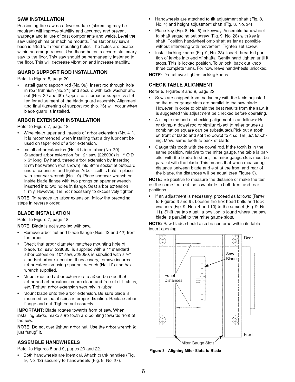
• Gauge this tooth with the dowel rod. If the tooth is in the
same position, relative to the miter gauge, the table is par-
allel with the blade. In short, the miter gauge slots must be
parallel with the blade. This means that when measuring
distance between blade and slot at the front and rear of
the blade, the distances will be equal (see Figure 3).
NOTE: Be positive to measure the distance or make the test
on the same tooth of the saw blade in both front and rear
positions.
• If an adjustment is necessary, proceed as follows: (Refer
to Figures 3 and 9). Loosen the hex head bolts and lock
washers (Fig. 9, Nos. 4 and 10) to the cabinet (Fig. 9, No.
11). Shift the table until a position is found where the saw
blade is parallel to the miter gauge slots.
NOTE: Saw blade should also be centered within its table
insert opening.
Rear
Front
ASSEMBLE HANDWHEELS
Refer to Figures 8 and 9, pages 20 and 22.
• Both handwheels are identical. Attach crank handles (Fig.
9, No. 13) securely to handwheels (Fig. 9, No. 27).
Miter Gauge Slots
Figure 3 - Aligning Miter Slots to Blade
6
Loading ...
Loading ...
Loading ...