Loading ...
Loading ...
Loading ...
ALLURE + QS3 SERmES
RANGE HOOD
®
Page 4
PREPARE THE HOOD PREPARE THE HOOD
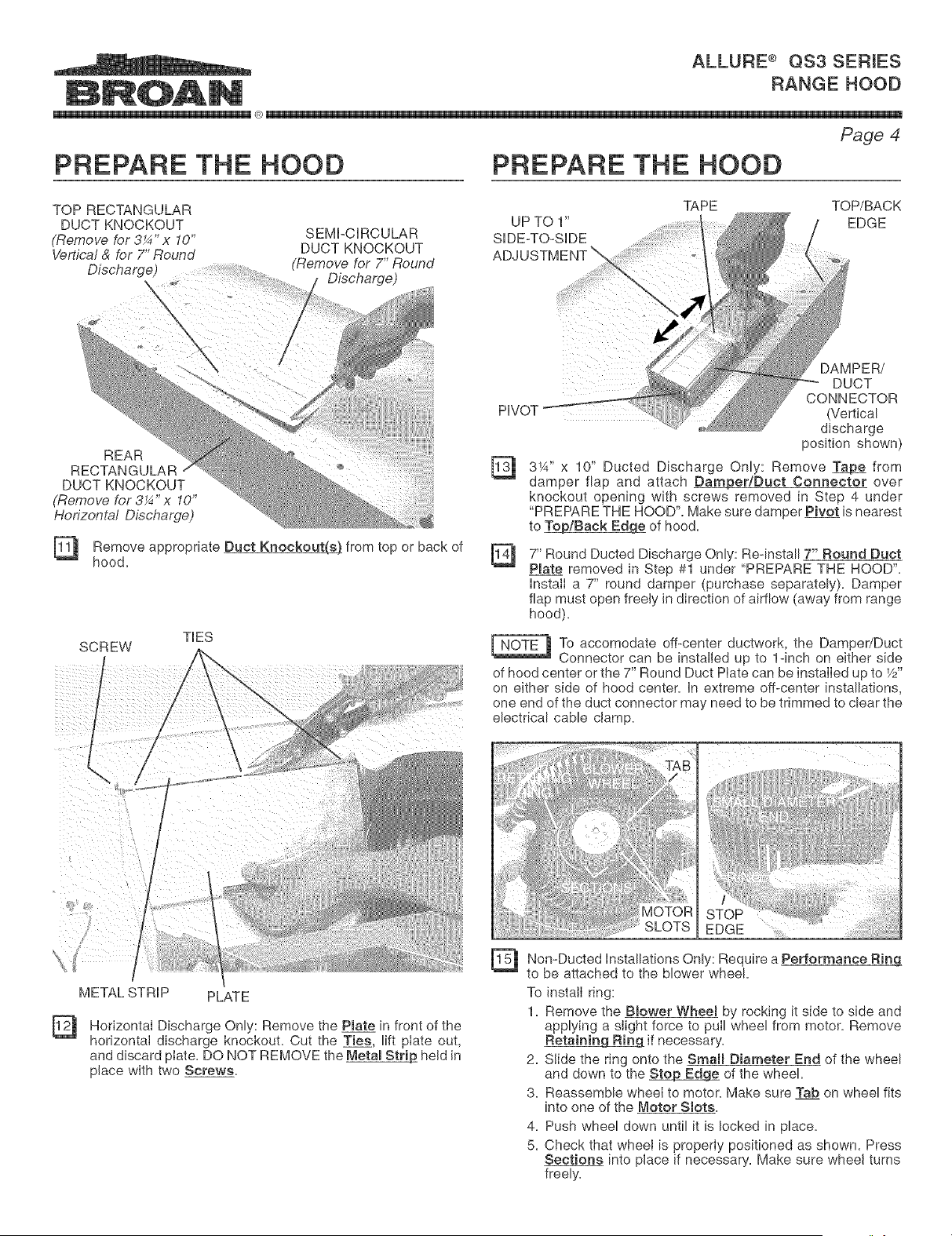
TOP RECTANGULAR TAPE TOP/BACK
DUCT KNOCKOUT UP TO 1" EDGE
(Remove for 3¼" x 10" SEMI+CIRCULAR SDE-TO-SDE
Vertical & for 7" Round DUCT KNOCKOUT
Discharge) (Remove for 7" Round
Discharge)
HVOT
REAR
RECTANGULAR
DUCT KNOCKOUT
(Remove for 3¼" x 10"
Horizontal Discharge)
[_ Remove appropriate Duct Knockouts(A). from or back of
hood. top [_
SCREW
/
/
/
TES
l
/
t
/
/
"--. /
/
METAL STRIP PLATE
Horizontal Discharge Only: Remove the Pmatein front of the
horizontal discharge knockout. Cut the Ties, lift plate out,
and discard plate. DO NOT REMOVE the Metal Strip held in
place with two Screws.
DAMPER/
DUCT
CONNECTOR
(Vertical
discharge
position shown)
3¼" x 10" Ducted Discharge Only: Remove _ from
damper flap and attach Damper/Duct Connector over
knockout opening with screws removed in Step 4 under
"PREPARE THE HOOD". Make sure damper Pivot is nearest
to B/Back Edge of hood.
7" Round Ducted Discharge Only: Re-install 7" Round Duct
Plate removed in Step #1 under "PREPARE THE HOOD".
InstalI a 7" round damper (purchase separately). Damper
flap must open freely in direction of airflow (away from range
hood).
_To accomodate off-center ductwork, the Damper/Duct
Connector can be installed up to 1-inch on either side
of hood center or the 7" Round Duct Plate can be installed up to _/z"
on either side of hood center. In extreme off-center installations,
one end of the duct connector may need to be trimmed to clear the
electrical cable clamp.
SLOTS EDGE ....
[1_ Non-Ducted Installations Only: Require a Performance Ring
to be attached to the blower wheel.
To install ring:
1. Remove the Blower WheeB by rocking it side to side and
applying a slight force to pull wheel from motor. Remove
Retainin_ if necessary.
2. Slide the ring onto the Small Diameter End of the wheel
and down to the _ of the wheel.
3. Reassemble wheel to motor. Make sure Tab on wheel fits
into one of the Motor Slots.
4. Push wheel down until it is locked in place.
5. Check that wheel is properly positioned as shown. Press
Sections into place if necessary. Make sure wheel turns
freely.
Loading ...
Loading ...
Loading ...