Loading ...
Loading ...
Loading ...
Page5
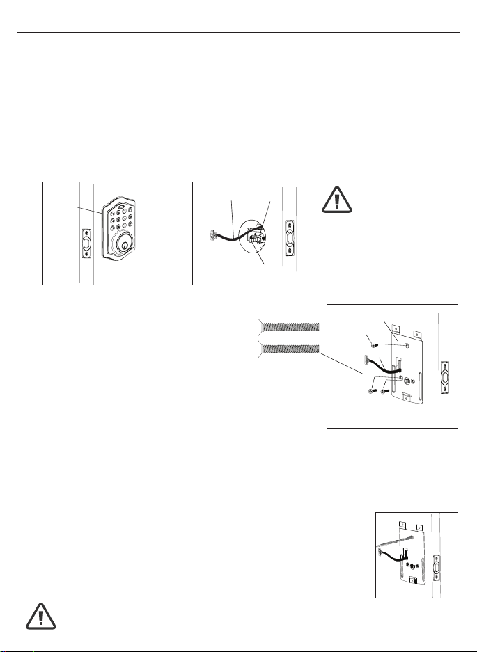
2. SECURING THE EXTERIOR ASSEMBLY TO THE DOOR
a.Fromthesidemarked“Thissideagainst
door”,routetheControlWirethroughthe
rectangular slot in the Mounting Plate
(Figure2a).
b.PlaceMountingPlateagainstdoorwithtailpiecepassing
throughthecenterholeinthethreeholeset(Figure2b).
c.SecuretheMountingPlatetotheExteriorAssemblyusing
two1”(25mm)Screws(Figure2c).
d.HandtightenwithaPhillipsScrewdriverleavinglooselyconnected(Figure2d).
e. Check that the Rubber Gasket is properly aligned and correct as necessary
(Figure2e).
f.Checkverticalalignmentofthelock(Figure2f).
g.TightensecurelywithahandheldPhillipsScrewdriver.DO NOT OVER TIGHTEN
3. OPTIONAL INSTALLATION
a.Usinga1/16”(2mm)drillbit,drillapilotholeinyourdoorusingthe
MountingPlateupperholeasaguide(Figure3a).
b. Insert one 3/4”(19mm)screwandtighten.
1. INSTALLING THE EXTERIOR ASSEMBLY
WorkwiththeDoorOpenforeasyaccess.
a.UnpacktheExteriorAssembly.Usecaretonotscratchthegreencircuitboard
during handling and installation.
b.CheckthattheRubberGasketisproperlyseatedontheExteriorAssembly
(Figure1a).
c.InserttheExteriorAssemblyontothedoorwiththetailpiecegoingthroughthe
Deadbolt Latch Set cross shaped spindle connector in the VERTICAL POSITION.
RoutetheControlWirethroughthedoorovertheDeadboltLatchSet(Figure1b).
NOTE: Deadbolt Latch must be retracted when installing
NOTE: Tailpiece must be
positioned vertically
NOTE: You are standing outside the door
INSTALLINGEXTERIORASSEMBLY
Right handed door view
Rubber
Gasket
Control
Wire
Tailpiece
(Vertical)
Latch
Hole
Mounting Plate
3/4”(19mm)screw
(OptionalInstallation)
1”(25mm)screws
Control Wire
Figure1a Figure1b
Figure3a
Figure2a-2f
NOTE: Lock and unlock using the key to see if
the Deadbolt Latch is opening and closing easily.
Loading ...
Loading ...
Loading ...