Loading ...
Loading ...
Loading ...
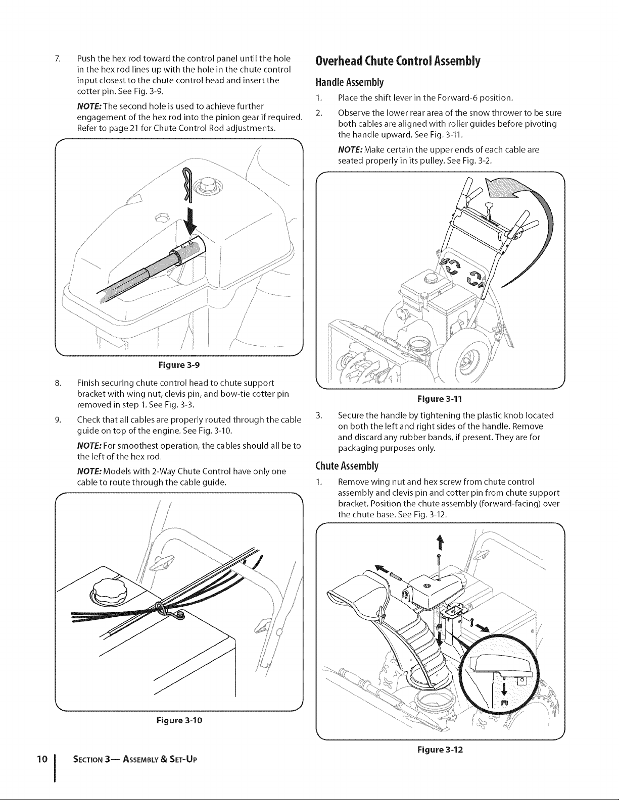
Push the hex rod toward the control panel until the hole
in the hex rod lines up with the hole in the chute control
input closest to the chute control head and insert the
cotter pin. See Fig. 3-9.
NOTE:The second hole is used to achieve further
engagement of the hex rod into the pinion gear if required.
Refer to page 21 for Chute Control Rod adjustments.
/
//'
/
,/
,//
/
..................................
/
/
Figure 3-9
8_
9_
Finish securing chute control head to chute support
bracket with wing nut, clevis pin, and bow-tie cotter pin
removed in step 1. See Fig. 3-3.
Check that all cables are properly routed through the cable
guide on top of the engine. See Fig. 3-10.
NOTE: For smoothest operation, the cables should all be to
the left of the hex rod.
NOTE:Models with 2-Way Chute Control have only one
cable to route through the cable guide.
J
Figure 3-10
SECTION 3-- ASSEMBLY& SET-UP
OverheadChuteControl Assembly
HandleAssembly
1. Place the shift lever in the Forward-6 position.
2. Observe the lower rear area of the snow thrower to be sure
both cables are aligned with roller guides before pivoting
the handle upward. See Fig. 3-11.
NOTE: Make certain the upper ends of each cable are
seated properly in its pulley. See Fig. 3-2.
f
Figure 3-11
3_
Secure the handle by tightening the plastic knob located
on both the left and right sides of the handle. Remove
and discard any rubber bands, if present. They are for
packaging purposes only.
ChuteAssembly
1. Remove wing nut and hex screw from chute control
assembly and clevis pin and cotter pin from chute support
bracket. Position the chute assembly (forward-facing) over
the chute base. See Fig. 3-12.
J
Figure 3-12
Loading ...
Loading ...
Loading ...