Loading ...
Loading ...
Loading ...
W415-2197 / 12.05.16
45
EN
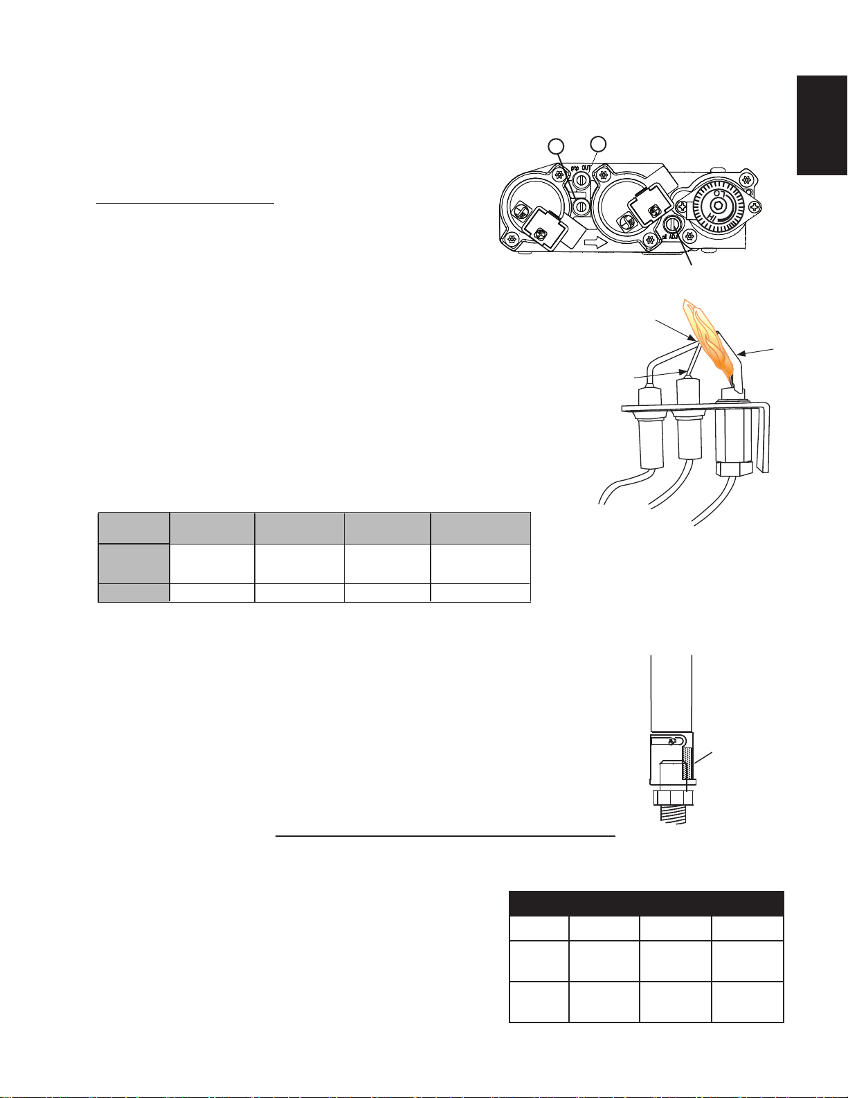
This appliance has an air shutter that has been factory set open according
to the chart below:
Regardless of venturi orientation, closing the air shutter will cause a more
yellow flame, but can lead to carbonization. Opening the air shutter will
cause a more blue flame, but can cause flame lifting from the burner ports.
The flame may not appear yellow immediately; allow 15 to 30 minutes for
the final flame colour to be established.
AIR SHUTTER ADJUSTMENT MUST ONLY BE DONE BY A QUALIFIED
INSTALLER!
AIR
SHUTTER
OPENING
VENTURI
BURNER
ORIFICE
49.1
To access the air shutter, remove the control access panel, remove the glass door assembly and carefully remove
the log set. Remove the four screws attached to the burner pan. Slide the burner pan to the left roughly 1” (25mm)
then lift up.
Air shutters have been factory set open according to the Venturi
Adjustment Chart. These settings are for (maximum) horizontal
termination. Adjustment may be required depending on fuel type,
vent configuration and altitude.
VENTURI ADJUSTMENT CHART
FUEL HD35-1 HD40-1 HD46-1
NG 1/8"
(3mm)
1/8"
(3mm)
1/8"
(3mm)
P 3/8"
(10mm)
7/16"
(11mm)
3/8"
(10mm)
10.0 ADJUSTMENT
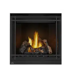
10.1 PRESSURE ADJUSTMENT
10.2 VENTURI ADJUSTMENT
Adjust the pilot screw to provide properly sized flame. Turn in a
clockwise direction to reduce the gas flow.
Check Pressure Readings:
Inlet pressure can be checked by turning screw (A) counter-clock-
wise 2 or 3 turns and then placing pressure gauge tubing over the
test point. Gauge should read as described on the chart below.
Check that main burner is operating on “HI”.
Outlet pressure can be checked the same as above using screw (B). Gauge
should read as described on the chart below. Check that main burner is operat-
ing on “HI”.
AFTER TAKING PRESSURE READINGS, BE SURE TO TURN SCREWS
CLOCKWISE FIRMLY TO RESEAL. DO NOT OVER TORQUE.
Leak test with a soap and water solution.
Prior to pilot adjustment, ensure that the pilot assembly has not been painted. If
overspray or painting of the pilot assembly has occurred remove the paint from
the pilot assembly, or replace. Fine emery cloth or sandpaper can be used to
remove the paint from the pilot hood, electrode and flame sensor.
*Maximum inlet pressure not to exceed 13”.
Pressure
Inlet
Outlet
Natural Gas
(inches)
Natural Gas
(millibars)
Propane
(inches)
Propane
(millibars)
*7"
(MIN. 4.5”)
3.5"
13"
(MIN. 11")
10"
17.4mb
(MIN. 11.2mb)
8.7mb
32.4mb
(MIN. 27.4mb)
24.9mb
FLAME MUST ENVELOP UPPER
3/8” (9.5mm) TO 1/2” (12.7mm)
OF FLAME SENSOR
PILOT
BURNER
FLAME
SENSOR
ELECTRODE
A
B
PILOT SCREW
Loading ...
Loading ...
Loading ...