Loading ...
Loading ...
Loading ...
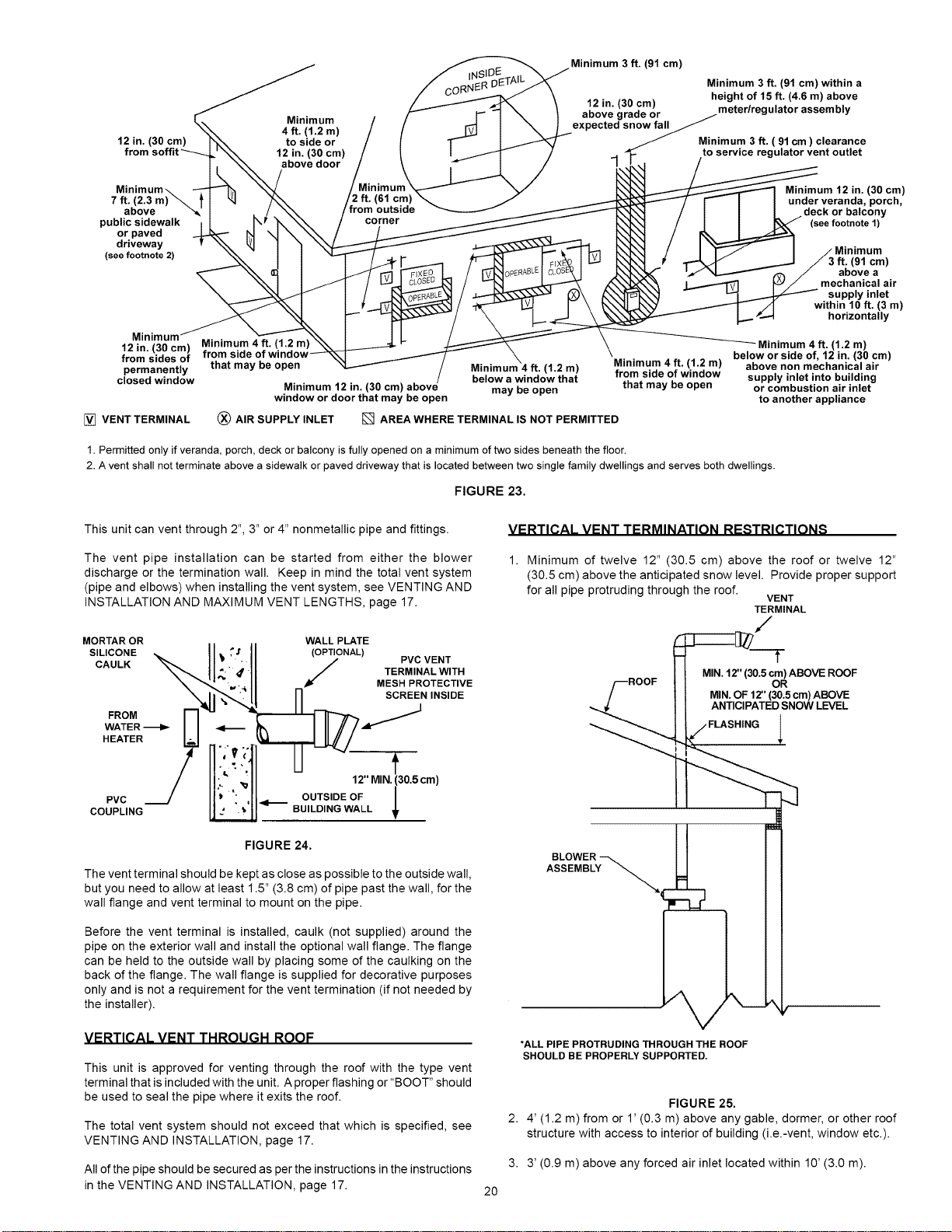
Minimum3 ft. (91 cm)
Minimum 3ft. (91 cm) within a
• height of 15 ft. (4.6 m) above
a12o_/_(30_n) r meter/regulator assembly
Minimum expected snowfall J
12 in. (30 cm) r'_ to side or _ Minimum3 ft. ( 91cm) clearance
from soffit'_---_L ' _ 12 in. (30 cm) _ _ , /to service regulator vent outlet
l-k_ ibovedoor _\_,,._ /__7_ /_
Minimum\ _ _ / li imul , [_. _....._ Minimum12 in. (30 cm)
7 ft. (2.3 m) _. _ I _ _k,_ /2 ft. (61 cml ["-- I I under veranda,porch,
above " _"_' I L J._ //from outsiae __XI / I I I .deck or balcony
publicsidewalk I I r_r "Ix _ / corner ___ kX_k_ / I I _ (seefootnote1)
orpaved _ N \1 \ \\ / / __ _ _._X,"t / _ I
(seder_Vetnway 2) _ i / N _ _ _ _/ _ _'_ Mi'n9r_Umm
ab(_vea )
\ \\ I I / Jt / L_ 1 CLW_ / _-[X] _ _.\X_-_--'_ I% _/ mechanical air
_XI_.--_ 1 / _, _E / _ _)\ _'_'_ _ _ _ supply inlet
"_'-_. I i __ / _ L_, I- \ _J..._'X_ / _..--------'-"F- ./I within l0 ft. (3 m)
i- "_ /_..__ I..,,..'_--"1 horizontally
12Mi/?lfl_m) Minimum 4_. (1.2 m)_'_ _ I-- _ \ _ Minimum 4ft. (1.2 m)
_°mm_idenSt_yffr_h_¢imdey°bfeWopd°w __ Minimum 4 ft. (1.2 m) MiTAmum4_t_il"2mw) bela_W°rSiode°_J2a_Gc_OCm)
closed window below awindow that o sae o ao supply inlet intobuilding
Minimum 12 in.(30 cm) above may be open that may be open or combustionair inlet
window ordoor that may be open to another appliance
[] VENT TERMINAL (_) AIR SUPPLYINLET [] AREAWHERE TERMINAL IS NOT PERMITTED
1. Permitted only if veranda, porch, deck or balcony is fully opened on a minimum of two sides beneath the floor.
2. A vent shall not terminate above a sidewalk or paved driveway that is located between two single family dwellings and serves both dwellings.
FIGURE 23.
This unit can vent through 2", 3" or 4" nonmetallic pipe and fittings.
The vent pipe installation can be started from either the blower
discharge or the termination wall. Keep in mind the total vent system
(pipe and elbows) when installing the vent system, see VENTING AND
INSTALLATION AND MAXIMUM VENT LENGTHS, page 17.
MORTAR OR
SILICONE
CAULK
FROM
WATER
HEATER
PVC
COUPLING
_;t. i
_; 4.!
'_ ° _
• °. i
WALL PLATE
(OPTIONAL)
J PVC VENT
TERMINAL WITH
MESH PROTECTIVE
_N INSIDE
12"MIN.(30.5cm)
OUTSIDE OF L
_1_ BUILDING WALL
FIGURE 24.
The vent terminal should be kept as close as possible to the outside wall,
but you need to allow at least 1.5" (3.8 cm) of pipe past the wall, for the
wall flange and vent terminal to mount on the pipe.
Before the vent terminal is installed, caulk (not supplied) around the
pipe on the exterior wall and install the optional wall flange. The flange
can be held to the outside wall by placing some of the caulking on the
back of the flange. The wall flange is supplied for decorative purposes
only and is not a requirement for the vent termination (if not needed by
the installer).
VERTICAL VENT THROUGH ROOF
This unit is approved for venting through the roof with the type vent
terminal that is included with the unit. A proper flashing or "BOOT" should
be used to seal the pipe where it exits the roof.
The total vent system should not exceed that which is specified, see
VENTING AND INSTALLATION, page 17.
VERTICAL VENT TERMINATION RESTRICTIONS
1. Minimum of twelve 12" (30.5 cm) above the roof or twelve 12"
(30.5 cm) above the anticipated snow level. Provide proper support
for all pipe protruding through the roof.
VENT
TERMINAL
/--ROOF _0.5 C_R)ABOVEROOF
/ II MIN°OF12"(30.5cm)ABOVE
I I ANTICIPATEDSNOWLEVEL
*ALL PIPE PROTRUDING THROUGH THE ROOF
SHOULD BE PROPERLY SUPPORTED.
FIGURE 25.
2. 4' (1.2 m) from or 1' (0.3 m) above any gable, dormer, or other roof
structure with access to interior of building (i.e.-vent, window etc.).
3. 3' (0.9 m) above any forced air inlet located within 10' (3.0 m).
All of the pipe should be secured as per the instructions in the instructions
in the VENTING AND INSTALLATION, page 17.
20
Loading ...
Loading ...
Loading ...