Loading ...
Loading ...
Loading ...
1.Placeboilerinlhe selectedlocation(asnearchimneyaspossible.)Your
boilerisshippedassembled.YouneedonlytoinstallIheBeliefValveand
a drainlinetocarryanywateror steamtoadrain.
2. InstallRebelValveintothe3/+,,pipeonthetopoftheboiler.SeeFigure5.
Use3/4"Pipeandanelbow(notfurnished)tocarrythewaterorsteamto
a nearbydrain.Donotconnectdirectlytoadrainbutleaveanairgap.No
shutoffofanydescriptionshallbeplacedbetweenthesafetyreliefvalve
andtheboiler,or ondischargepipesbetweensuchsafetyvalvesandthe
atmosphere.Installationol thesafetyreliefvalveshallconformto lhe
requirementsof the ANSI/ASMEBoiler and PressureVesselCode,
SectionIV.Themanufactureris notresponsibleforanywaterdamage.
InstallDrainValvein lowerleftsideof boilerasmarked.
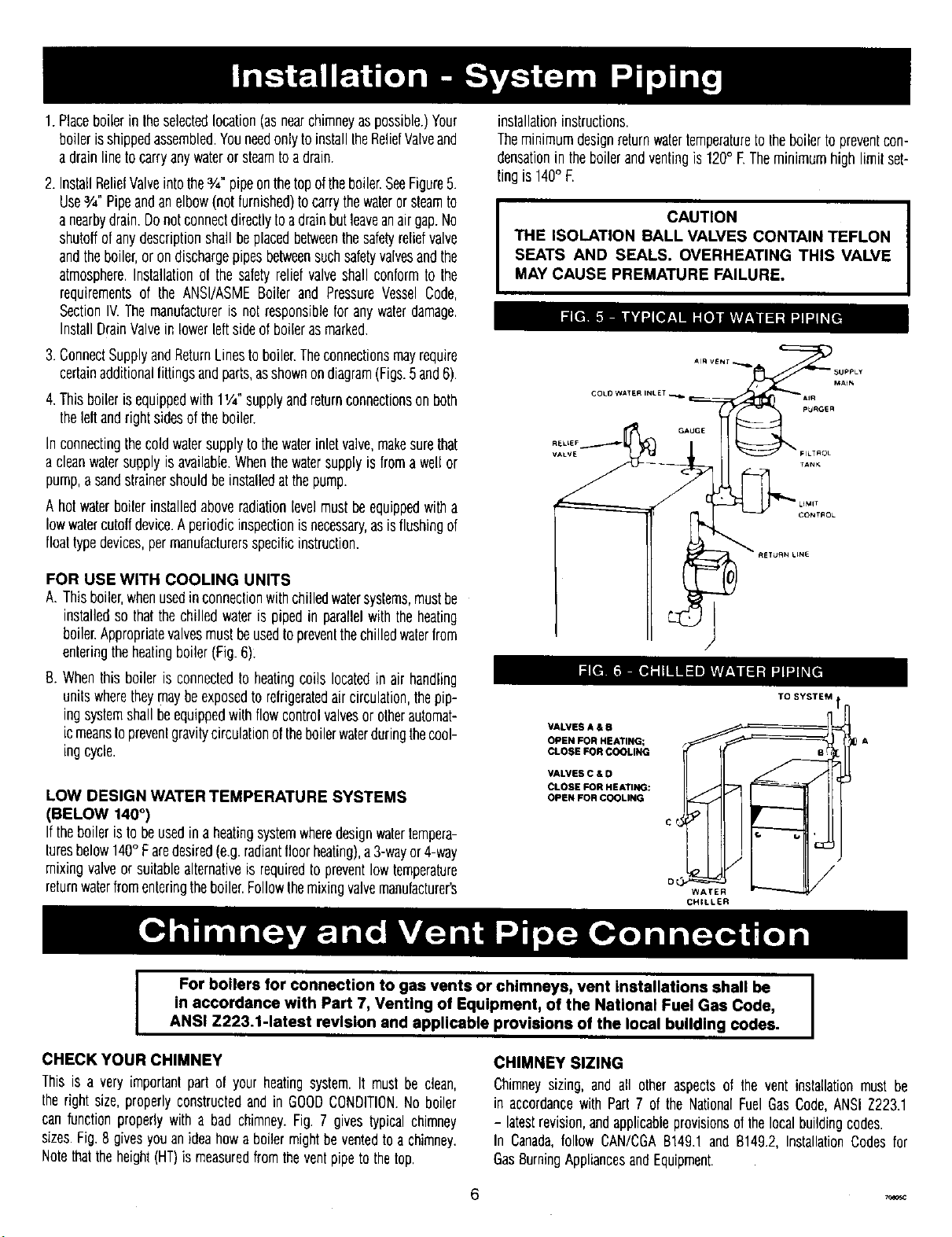
3.ConnectSupplyandReturnLinestoboiler.Theconnectionsmayrequire
certainadditionalfittingsandparts,asshownondiagram(Figs.5and6).
4.Thisboilerisequippedwith 11/4"supplyandreturnconnectionsonboth
theleltandrightsidesoftheboiler.
Inconnectingthecoldwatersupplytothewaterinlelvalve,makesurethat
a cleanwatersupplyisavailable.Whenthewatersupplyisfroma wellor
pump,a sandstrainershouldbeinstalledatthepump.
A hotwaterboilerinstalledaboveradiationlevelmustbeequippedwitha
lowwatercutoffdevice.A periodicinspectionisnecessary,asisflushingof
floatlypedevices,permanufacturersspecificinstruction.
FOR USE WITH COOLING UNITS
A.Thisboiler,whenusedinconnectionwithchilledwatersystems,mustbe
installedsothatthechilledwateris pipedin parallelwiththeheating
boiler.Appropriatevalvesmustbeusedtoprevenlthechilledwaterfrom
enteringtheheatingboiler(Fig.6)_
B.Whenthis boiler is connectedto heatingcoils locatedin air handling
unitswheretheymaybeexposedto relrigeratedair circulation,thepip-
ingsystemshallbeequippedwithflowcontrolvalvesor otherautomat-
icmeanstopreventgravitycirculationoftheboilerwaterduringthecool-
ingcycle.
LOW DESIGN WATER TEMPERATURE SYSTEMS
(BELOW 140+)
If theboileristo beusedina heatingsystemwheredesignwalertempera-
luresbelow140° Faredesired(e.g.radiantfloorheating),a3-wayor4-way
mixingvalveor suitablealternativeis requiredto preventlowtemperature
returnwaterfromenteringtheboiler.Followthemixingvalvemanufacturer's
installationinstructions.
Theminimumdesignreturnwatertemperaturetotheboilertopreventcon-
densationin theboilerandventingis 120° E Theminimumhighlimit set-
tingis140° E
I CAUTION
THE ISOLATION BALL VALVES CONTAIN TEFLON
SEATS AND SEALS. OVERHEATING THIS VALVE
MAY CAUSE PREMATURE FAILURE.
COLD WATER INLET --
RELLEFJ[
VALVES A & B
OPEN FOR HEATING;
CLOSE FOR COOLING
VALVES C & D
CLOSE FOR HEATING:
OPEN FOR COOLING
TO SYSTEM
CHILLER
IDA
For boilers for connection to gas vents or chimneys, vent installations shall be
in accordance with Part 7, Venting of Equipment, of the National Fuel Gas Code,
ANSI Z223.1-1atest revision and applicable provisions of the local building codes.
CHECK YOUR CHIMNEY
This is a very importantpart of your heatingsystem.It mustbe clean,
the rightsize,properlyconstructedandin GOODCONDITION.Noboiler
canfunctionproperlywith a bad chimney.Fig. 7 givestypicalchimney
sizes.Fig.8 givesyouanideahowa boilermightbe ventedtoa chimney.
Notethattheheight(HT)is measuredfromtheventpipetothetop.
CHIMNEY SIZING
Chimneysizing, and all otheraspectsof the vent installationmustbe
in accordancewith Part7 of the NationalFuelGasCode,ANSIZ223.1
- latestrevision,andapplicableprovisionsofthelocalbuildingcodes.
In Canada,follow CAN/CGAB149.1andB149.2,InstallationCodesfor
GasBurningAppliancesandEquipment.
Loading ...
Loading ...
Loading ...