OPERATOR'S MANUAL
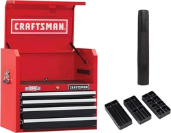
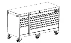
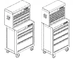
STANDARD DUTY TOOL CHESTS
• Periodically the drawer fronts, drawer trim, and other surfaces
should be cleaned with a mild detergent and water.
• Auto wax will preserve the unit's luster finish. Apply the wax as
to a car. The wax will also help protect the unit against scratch-
es.
• Grease and oil can be removed with most standard cleaning
fluids. For safety, use a nonflammable cleaning fluid.
• If drawer liners are supplied, it is recommended they are used
to protect the finish inside the drawers and to make the drawers
easier to clean. The drawer liners may be cleaned with soap and
water.
* Product you purchased may vary from picture shown
CALL 1=800-833-4405 FOR SERVICE PARTS. Please have
model number ready at time of call.
LOCATING MODEL # iNFORMATiON
Model number and other information required for service parts is
on a label located on the interior right side of the top most drawer.
• The maximum weight for each drawer should be no more than
30 pounds.
• The maximum product weight, including contents, should be no
more than 500 pounds for cabinets; maximum including con-
tents, 300 pounds for tool centers.
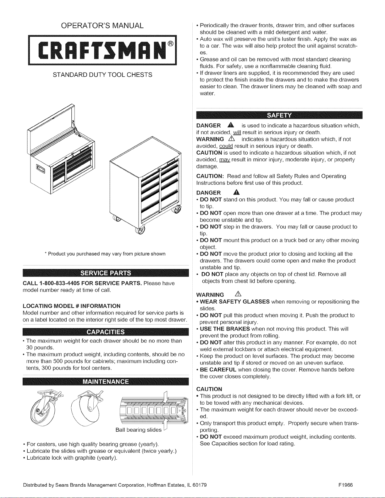
• For casters, use high quality bearing grease (yearly).
• Lubricate the slides with grease or equivalent (twice yearly.)
• Lubricate lock with graphite (yearly).
DANGER ,_ is used to indicate a hazardous situation which,
if not avoided, will result in serious injury or death.
WARNING ,4X indicates a hazardous situation which, if not
avoided, could result in serious injury or death.
CAUTION is used to indicate a hazardous situation which, if not
avoided, m_m.g_V_result in minor injury, moderate injury, or property
damage.
CAUTION: Read and follow all Safety Rules and Operating
Instructions before first use of this product.
DANGER ,_,
• DO NOT stand on this product. You may fall or cause product
to tip.
• DO NOT open more than one drawer at a time. The product may
become unstable and tip.
• DO NOT step in the drawers. You may fall or cause product to
tip.
• DO NOT mount this product on a truck bed or any other moving
object.
• DO NOT move the product prior to closing and locking all the
drawers. The drawers could come open and make the product
unstable and tip.
• DO NOT place any objects on top of chest lid. Remove all
objects from chest lid before opening.
WARNING Z_
• WEAR SAFETY GLASSES when removing or repositioning the
slides.
• DO NOT pull this product when moving it. Push the product to
prevent personal injury.
• USE THE BRAKES when not moving this product. This will
prevent the product from rolling.
• DO NOT alter this product in any manner. For example, do not
weld external Iockbars or attach electrical equipment.
• Keep the product on level surfaces. The product may become
unstable and tip if stored or moved on an uneven surface.
• BE CAREFUL when closing the cover. Remove hands before
the cover closes completely.
CAUTION
This product is not designed to be directly lifted with a fork lift, or
to be towed with any mechanical devices.
• The maximum weight for each drawer should never be exceed-
ed.
• Only transport this product empty. Properly secure when trans-
porting.
• DO NOT exceed maximum product weight, including contents.
See Capacities section for load rating.
Distributed by Sears Brands Management Corporation, Hoffman Estates, IL 60179 F1966
Tools Required:
3/8 inch wrench Screwdriver
7/16-in wrench 5/16-inch drill bit
CABINET HARDWARE INCLUDED:
1/4 - 20 x 5/8" Screw (Qty: 16)
1/4- 20 Nut (Qty: 16)
1/4 - 20 x 5/8" Screw (Qty: 16)
1/4 - 20 Nut (Qty: 16)
7/16-in Wrench
3/8-in Wrench
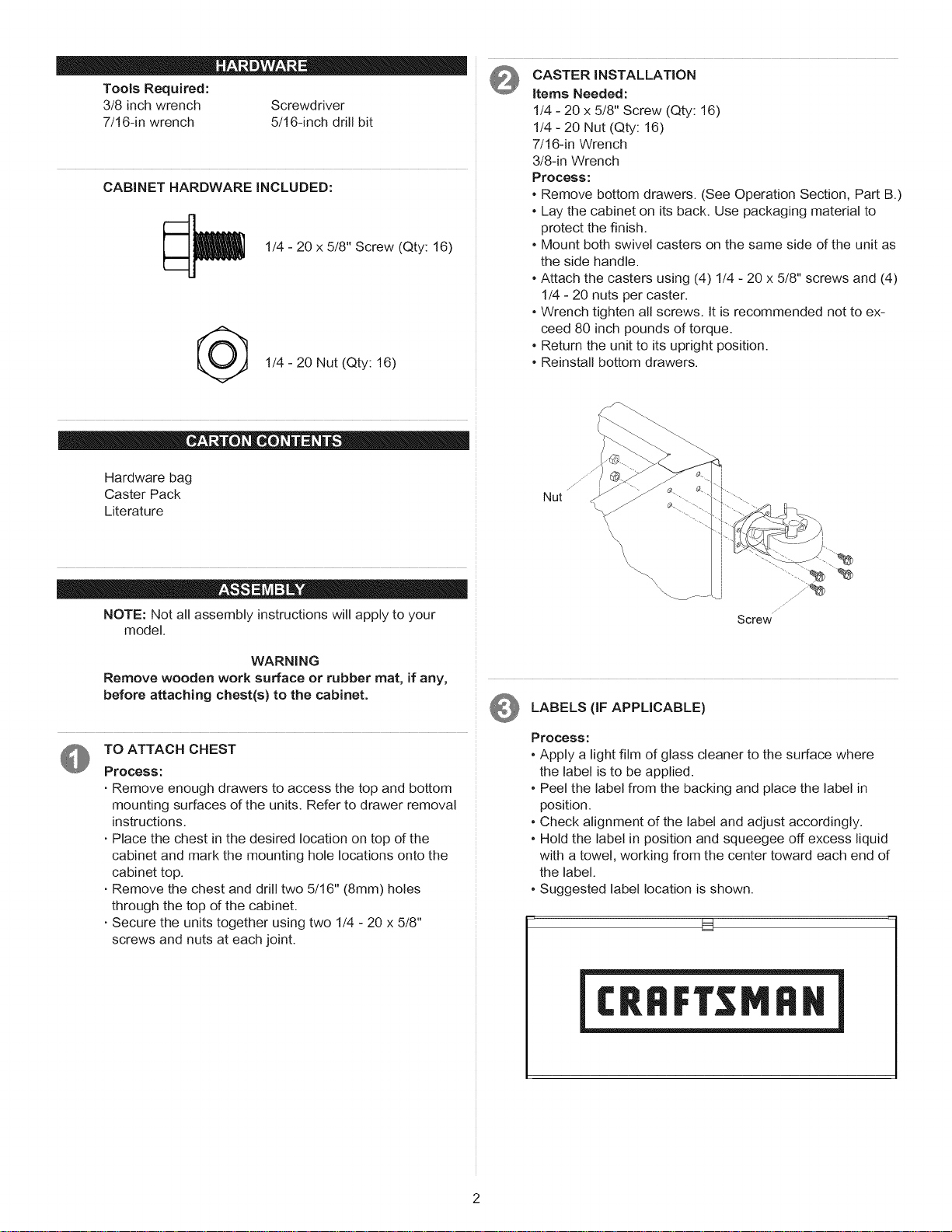
Process:
• Remove bottom drawers. (See Operation Section, Part B.)
• Lay the cabinet on its back. Use packaging material to
protect the finish.
• Mount both swivel casters on the same side of the unit as
the side handle.
• Attach the casters using (4) 1/4 - 20 x 5/8" screws and (4)
1/4 - 20 nuts per caster.
• Wrench tighten all screws. It is recommended not to ex-
ceed 80 inch pounds of torque.
• Return the unit to its upright position.
• Reinstall bottom drawers.
Hardware bag
Caster Pack
Literature
NOTE: Not all assembly instructions will apply to your
model.
WARNING
Remove wooden work surface or rubber mat, if any,
before attaching chest(s) to the cabinet.
TO ATTACH CHEST
Process:
. Remove enough drawers to access the top and bottom
mounting surfaces of the units. Refer to drawer removal
instructions.
. Place the chest in the desired location on top of the
cabinet and mark the mounting hole locations onto the
cabinet top.
. Remove the chest and drill two 5/16" (8mm) holes
through the top of the cabinet.
. Secure the units together using two 1/4 - 20 x 5/8"
screws and nuts at each joint.
\,
\
\
\
Screw
LABELS (IF APPLICABLE)
Process:
° Apply a light film of glass cleaner to the surface where
the label is to be applied.
• Peel the label from the backing and place the label in
position.
• Check alignment of the label and adjust accordingly.
• Hold the label in position and squeegee off excess liquid
with a towel, working from the center toward each end of
the label.
• Suggested label location is shown.
U
NOTE: Not all operation instructions will relate to your
model.
TO LOCK CHEST
Process:
• Make sure drawers are fully closed.
• Insert the Iockbar (which stores in the top tray), tabbed
end up, into the slot in the top tray and down into the slot
in the base.
• Close the cover and lock with the key.
TO UNLOCK CHEST
• Reverse above procedure.
THE LOCKBAR FOR THE ROLLER CABINET IS
STORED IN A SLOT IN THE TOP FRONT CORNER OF
THE UNIT.
TO LOCK ROLLER CABINET
Process:
• Insert the straight end of the Iockbar into the slot in the
base.
• Move the Iockbar toward the unit until the bent end fits
into the slot near the lock.
• Lock with the key.
TO UNLOCK ROLLER CABINET
• Reverse above procedure.
NOTE: If your unit is equipped with a storage compartment
with a panel at the bottom, pull panel out, lift up and push
panel back into unit to gain access to compartment.
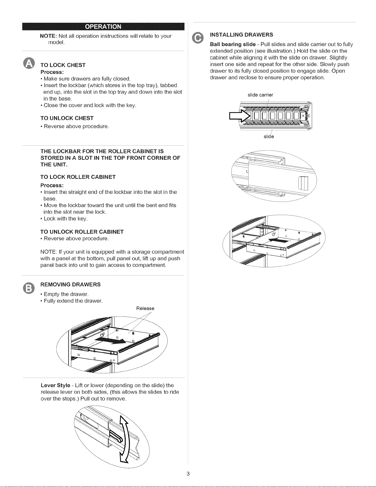
REMOVING DRAWERS
• Empty the drawer.
• Fully extend the drawer.
Release
INSTALLING DRAWERS
Ball bearing slide - Pull slides and slide carrier out to fully
extended position (see illustration.) Hold the slide on the
cabinet while aligning it with the slide on drawer. Slightly
insert one side and repeat for the other side. Slowly push
drawer to its fully closed position to engage slide. Open
drawer and reclose to ensure proper operation.
slide carrier
slid'e
Lever Style - Lift or lower (depending on the slide) the
release lever on both sides, (this allows the slides to ride
over the stops.) Pull out to remove.
\
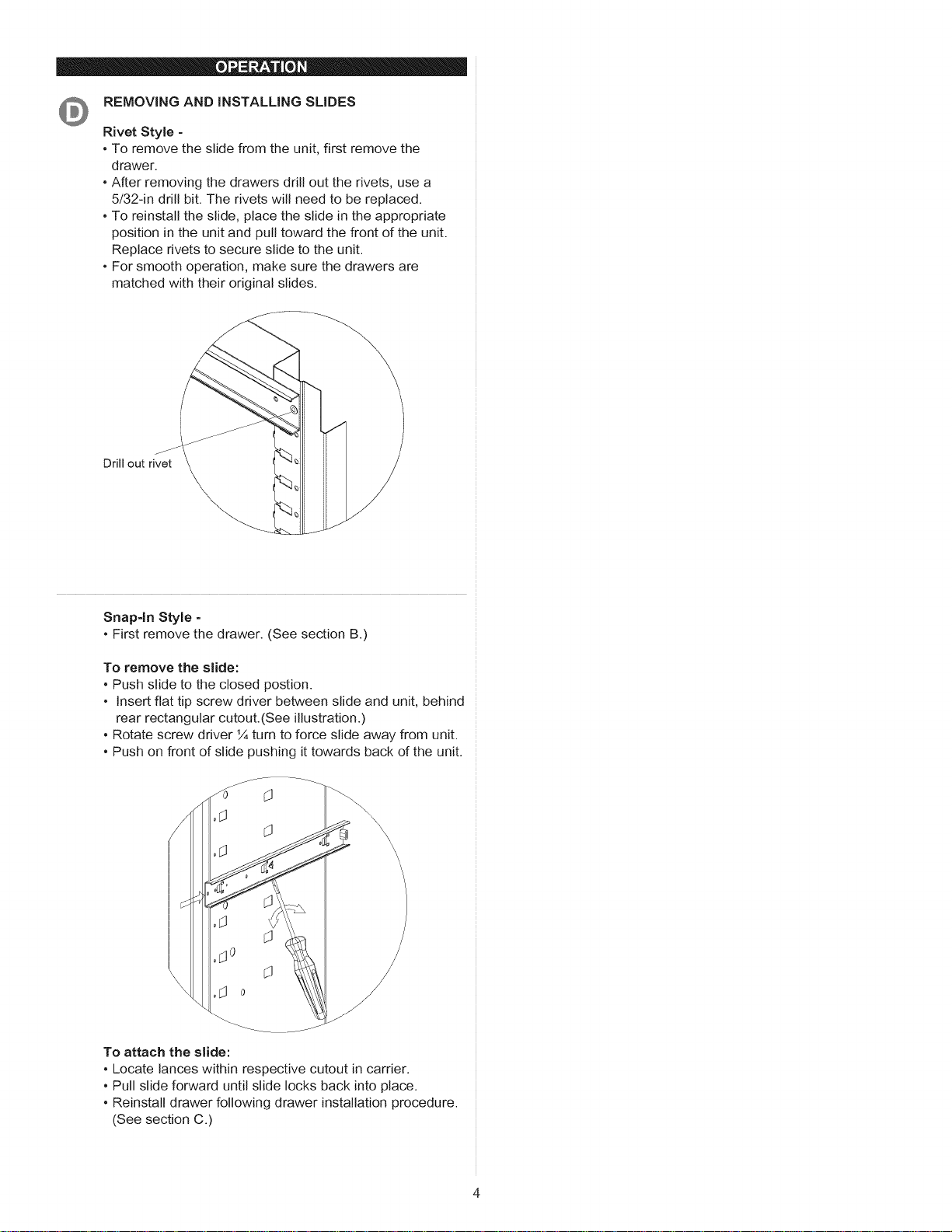
REMOVING AND iNSTALLiNG SLIDES
Rivet Style -
• To remove the slide from the unit, first remove the
drawer.
• After removing the drawers drill out the rivets, use a
5/32-in drill bit. The rivets will need to be replaced.
• To reinstall the slide, place the slide in the appropriate
position in the unit and pull toward the front of the unit.
Replace rivets to secure slide to the unit.
• For smooth operation, make sure the drawers are
matched with their original slides.
Drill out rivet
\
Snap-in Style -
• First remove the drawer. (See section B.)
To remove the slide:
• Push slide to the closed postion.
• Insert flat tip screw driver between slide and unit, behind
rear rectangular cutout.(See illustration.)
• Rotate screw driver ¼ turn to force slide away from unit.
• Push on front of slide pushing it towards back of the unit.
\
\
\
To attach the slide:
• Locate lances within respective cutout in carrier.
• Pull slide forward until slide locks back into place.
• Reinstall drawer following drawer installation procedure.
(See section C.)
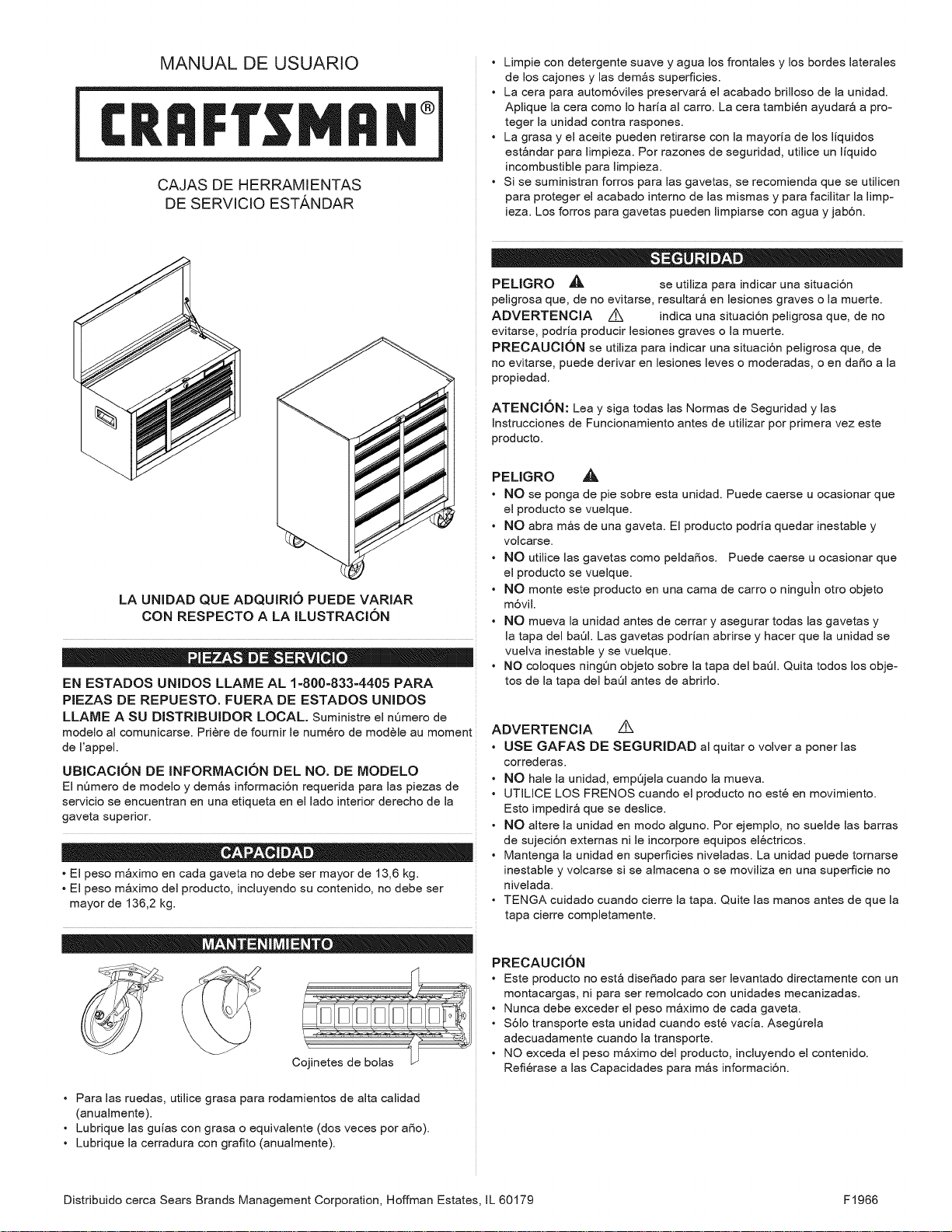
MANUAL DE USUARIO
CAJAS DE HERRAMIENTAS
DE SERVlClO ESTA,NDAR
LA UNIDAD QUE ADQUIRIO PUEDE VARIAR
CON RESPECTO A LA ILUSTRACION
EN ESTADOS UNIDOS LLAME AL 1=800=833-4405 PARA
PIEZAS DE REPUESTO. FUERA DE ESTADOS UNIDOS
LLAME A SU DISTRIBUIDOR LOCAL. SumJnistre el nQmero de
modelo al comunicarse. Pri@e de fournir le num@o de module au moment
de ['appe[.
UBICAClON DE INFORMAClON DEL NO. DE MODELO
El nQmero de modelo y demos informaci6n requerida para las piezas de
servicio se encuentran en una etiqueta en el lado interior derecho de la
gaveta superior.
• El peso m_ximo en cada gaveta no debe ser mayor de 13,6 kg.
• El peso m_ximo del producto, incluyendo su contenido, no debe ser
mayor de 136,2 kg.
• Para las ruedas, utilice grasa para rodamientos de alta calidad
(anualmente).
• Lubrique las guias con grasa o equivalente (dos veces por aSo).
• Lubrique la cerradura con grafito (anualmente).
• Limpie con detergente suave y agua los frontales y los bordes laterales
de los cajones y las demos superficies.
• La cera para autom6viles preservar_ el acabado brilloso de la unidad.
Aplique la cera como Io hada al carro. La cera tambi6n ayudar_ a pro-
teger la unidad contra raspones.
• La grasa y el aceite pueden retirarse con la mayoda de los liquidos
est_ndar para limpieza. Por razones de seguridad, utilice un liquido
incombustible para limpieza.
• Si se suministran forros para las gavetas, se recomienda que se utilicen
para proteger el acabado interno de las mismas y para facilitar la limp-
ieza. Los forros para gavetas pueden limpiarse con agua y jab6n.
PELIGRO J_, se utilJza para Jndicar una situaci6n
peligrosa que, de no evitarse, resultar_ en lesiones graves o la muerte.
ADVERTENClA /K indioa una situaci6n peligrosa que, de no
evitarse, podria producir Jesiones graves o Jamuerte.
PREOAUOKSN se utiliza para indicar una situaci6n peligrosa que, de
no evitarse, puede derivar en lesiones leves o moderadas, o en daSo a la
propiedad.
ATENClON: Lea y siga todas las Normas de Seguridad y las
InstruccJones de Funcionamiento antes de utilizar por primera vez este
producto.
PELIGRO J_,
• NO se ponga de pie sobre esta unidad. Puede caerse u ocasionar que
el producto se vuelque.
• NO abra m_s de una gaveta. El producto podria quedar inestable y
volcarse.
• NO utilice las gavetas como peldaSos. Puede caerse u ocasionar que
el producto se vuelque.
• NO monte este producto en una cama de carro o ninguin otro objeto
m6vil.
• NO mueva la unidad antes de cerrar y asegurar todas Jasgavetas y
la tapa del baOl. Las gavetas podrian abrirse y hacer que la unidad se
vuelva inestable y se vuelque.
• NO coloques ningOn objeto sobre la tapa del baOl. Quita todos los obje-
tos de la tapa del baOl antes de abrirlo.
ADVERTENCIA /K
• USE GAFAS DE SEGURIDAD al quitar o volver a poner las
correderas.
• NO hale la unJdad, empQjela cuando la mueva.
• UTILICE LOS FRENOS cuando el producto no est6 en movimiento.
Esto impedir_ que se deslice.
• NO altere la unJdad en modo alguno. Por ejemplo, no suelde las barras
de sujeci6n externas nile incorpore equipos el6ctricos.
• Mantenga la unidad en superficies niveladas. La unidad puede tornarse
inestable y volcarse si se almacena o se moviliza en una superficie no
nivelada.
• TENGA cuidado cuando cierre la tapa. Quite las manos antes de que la
tapa cierre completamente.
PRECAUCION
• Este producto no est_ dJseSado para ser levantado directamente con un
montacargas, ni para ser remolcado con unidades mecanizadas.
• Nunca debe exceder el peso m_ximo de cada gaveta.
• $61o transporte esta unidad cuando est6 vacia. AsegQrela
adecuadamente cuando la transporte.
• NO exceda el peso m_ximo del producto, incluyendo el contenido.
Refi@ase alas Capacidades para m_s informaci6n.
Distribuido cerca Sears Brands Management Corporation, Hoffman Estates, IL 60179 F1966
HERRAMIENTAS NECESARIAS:
Llave Inglesa de 3/8 inch
Llave Inglesa de 7/16 inch
Destornillador, punta de cruz
Broca de 5/16- in
TORNILLERiA INCLUiDA PARA EL GABINETE
Tornillo 1/4-20 x .625-in HW
(Cant: 16)
Tuerca Hexagonal de 1/4-20
(Cant: 16)
Bolsa de accesorios
Paquete de ruedas
Material impreso
NOTA: No todas las instrucciones de uso se refieren a tu
modelo.
ADVERTENCIA
Si el gabinete cuenta con alguna superficie de trabajo
de madera o goma, remuevala antes de montar el
cofre sobre este.
FIJACION DEL BAUL:
Proceso:
• Saca las gavetas necesarias para poder alcanzar el tope
y el fondo de las superficies de montaje de las unidades.
Consulta las instrucciones para sacar las gavetas.
• Coloca el ba01en el sitio elegido encima del gabinete y
marca los orificios de montaje en el tope del gabinete.
• Quite el ba01y taladre dos 5/16-in agujeros (de 8 mm)
pot la cumbre del gabinete o baQl intermedio.
• Fija las unidades en cada union con (2) tomillos 1/4 - 20
x 5/8-in y (2) tuercas 1/4 - 20.
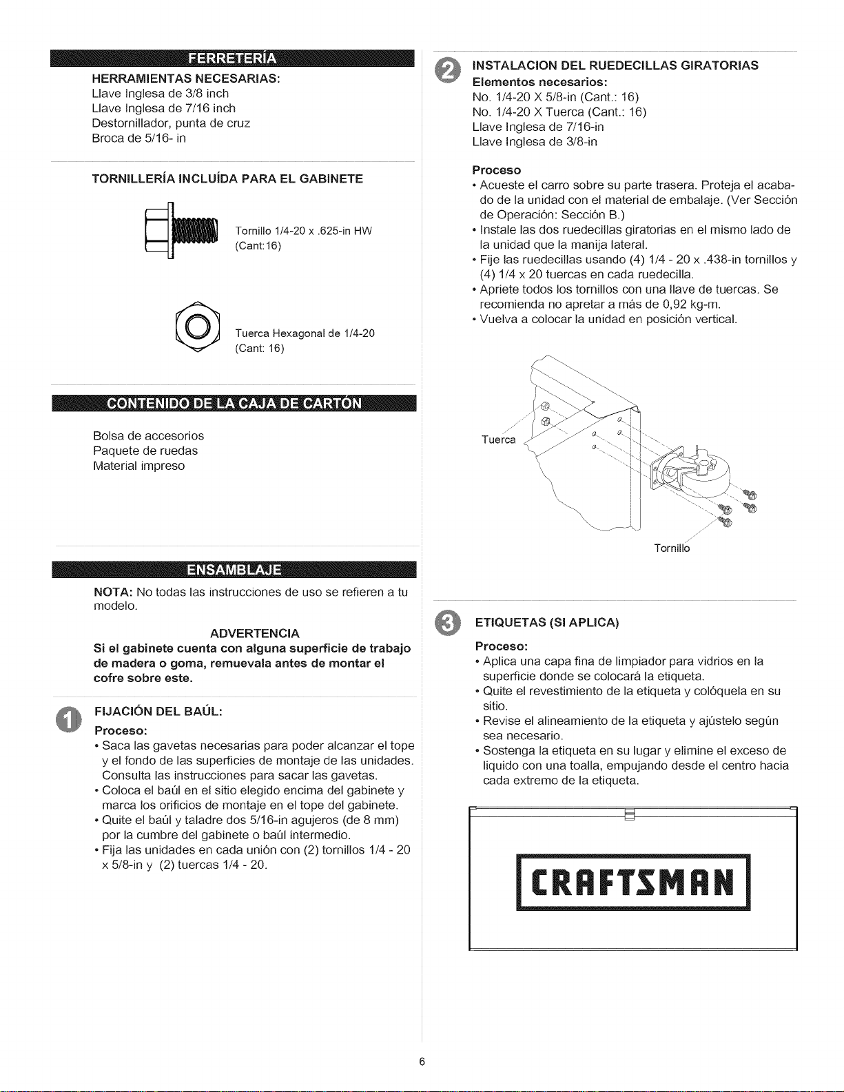
INSTALACION DEL RUEDECILLAS GIRATORIAS
Elementos necesarios:
No. 1/4-20 X 5/8-in (Cant.: 16)
No. 1/4-20 X Tuerca (Cant.: 16)
Llave Inglesa de 7/16-in
Llave Inglesa de 3/8-in
Proceso
• Acueste el carro sobre su parte trasera. Proteja el acaba-
do de la unidad con el material de embalaje. (Vet SecciOn
de OperaciOn: Secci0n B.)
• Instale las dos ruedecillas giratorias en el mismo lado de
la unidad que la manija lateral.
• Fije las ruedecillas usando (4) 1/4 - 20 x .438-in tomillos y
(4) 1/4 x 20 tuercas en cada ruedecilla.
• Apriete todos los tornillos con una Ilave de tuercas. Se
recomienda no apretar a mas de 0,92 kg-m.
• Vuelva a colocar la unidad en posiciOn vertical.
jJ
Tuerca ......
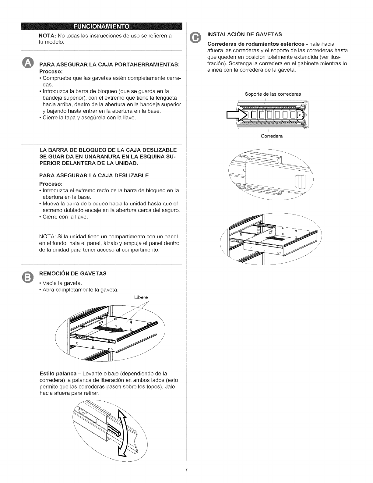
ETIQUETAS (Sl APMCA)
Proceso:
• Aplica una capa fina de limpiador para vidrios en la
superficie donde se colocar& la etiqueta.
° Quite el revestimiento de la etiqueta y colOquela en su
sitio.
° Revise el alineamiento de la etiqueta y ajOstelo segOn
sea necesario.
° Sostenga la etiqueta en su lugar y elimine el exceso de
liquido con una toalla, empujando desde el centro hacia
cada extremo de la etiqueta.
U
NOTA: No todas las instrucciones de uso se refieren a
tu modelo.
PARA ASEGURAR LA CAJA PORTAHERRAMIENTAS:
Proceso:
• Compruebe que las gavetas est6n completamente cerra-
das.
• Introduzca la barra de bloqueo (que se guarda en la
bandeja superior), con el extremo que tiene la lengQeta
hacia arriba, dentro de la abertura en la bandeja superior
y bajando hasta entrar en la abertura en la base.
• Cierre la tapa y asegOrela con la Ilave.
LA BARRA DE BLOQUEO DE LA CAJA DESMZABLE
SE GUAR DA EN UNARANURA EN LA ESQUINA SU-
PERIOR DELANTERA DE LA UNIDAD.
PARA ASEGURAR LA CAJA DESMZABLE
Proceso:
• Introduzca el extremo recto de la barra de bloqueo en la
abertura en la base.
• Mueva la barra de bloqueo hacia la unidad hasta que el
estremo doblado encaje en la abertura cerca del seguro.
• Cierre con la Ilave.
INSTALACI6N DE GAVETAS
Correderas de rodamientos esf_ricos - hale hacia
afuera las correderas y el soporte de las correderas hasta
que queden en posici6n totalmente extendida (ver ilus-
traciOn). Sostenga la corredera en el gabinete mientras Io
alinea con la corredera de la gaveta.
Soporte de Uascorrederas
/
/
Corredera
NOTA: Si la unidad tiene un compartimento con un panel
en el rondo, hala el panel, &lzalo y empuja el panel dentro
de la unidad para tener acceso al compartimento.
REMOCION DE GAVETAS
• Vacie la gaveta.
• Abra completamente la gaveta.
Libere
Estilo palanca - Levante o baje (dependiendo de la
corredera) la palanca de liberaciOn en ambos lados (esto
permite que las correderas pasen sobre los topes). Jale
hacia afuera para retirar.
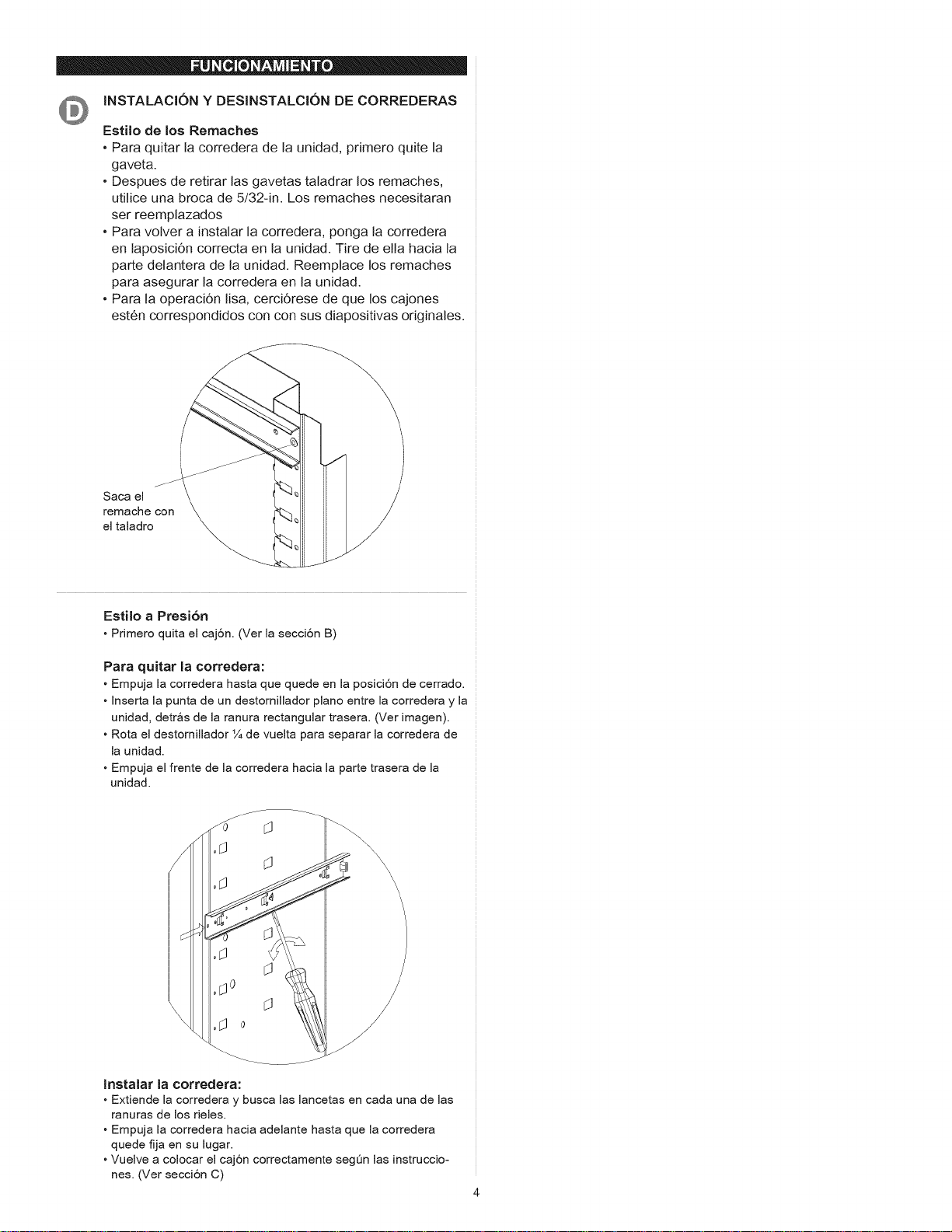
INSTALACION Y DESINSTALCION DE CORREDERAS
Estilo de los Remaches
• Para quitar la corredera de la unidad, primero quite la
gaveta.
• Despues de retirar las gavetas taladrar los remaches,
utilice una broca de 5/32-in. Los remaches necesitaran
ser reemplazados
• Para volver a instalar la corredera, ponga la corredera
en laposiciOn correcta en la unidad. Tire de ella hacia la
parte delantera de la unidad. Reemplace los remaches
para asegurar la corredera en la unidad.
• Para la operaci6n lisa, cerci6rese de que los cajones
est6n correspondidos con con sus diapositivas originales.
J
Saca el
remache con
el taladro
Estilo a Presi6n
• Primero quita el caj6n. (Ver la secci6n B)
Para quitar la corredera:
• Empuja la corredera hasta que quede en la posici6n de cerrado.
• Inserta la punta de un destomillador piano entre la corredera y la
unidad, detr_s de la ranura rectangular trasera. (Ver imagen).
• Rota el destomillador 1/4de vuelta para separar la corredera de
la unidad.
• Empuja el frente de la corredera hacia la parte trasera de la
unidad.
Instalar la corredera:
• Extiende la corredera y busca las lancetas en cada una de las
ranuras de los rieles.
• Empuja la corredera hacia adelante hasta que la corredera
quede fija en su lugar.
• Vuelve a colocar el caj6n correctamente segQn las instruccio-
nes. (Ver secci6n C)