
INSTALLATION
INSTRUCTIONS
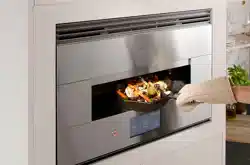
Indoor Hearth Oven
ZEP30FR
ENGLISH/ESPAÑOL.
MONOGRAM.COM
2 31-2001053 Rev. 0
Safety Information
READ AND SAVE THESE INSTRUCTIONS
FOR YOUR SAFETY
• Be sure your oven is installed properly by a qualified
installer or service technician.
• Be sure the oven is securely installed in a cabinet that
is firmly attached to the house structure. Never allow
anyone to climb, sit, stand or hang on the oven.
• Make sure the cabinets and wall coverings around
the oven can withstand the temperatures (up to
200°F [93.3°C]) generated by the oven.
WARNING
The electrical power to the
oven supply line must be shut off while line
connections are being made. Failure to do so
could result in serious injury or death.
ELECTRICAL REQUIREMENTS
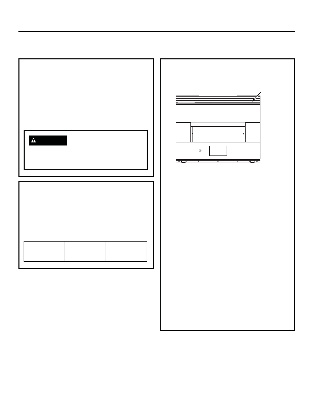
Rating plate is located on the top right of the front
panel.
We recommend you have the electrical wiring
and hookup of your oven connected by a qualified
electrician. After installation, have the electrician show
you how to disconnect power from the range.
Check with your local utilities for electrical codes
which apply in your area. Failure to wire your oven
according to governing codes could result in a
hazardous condition. If there are no local codes,
your oven must be wired and fused to meet the
requirements of the National Electrical Code, NFPA
No. 70–Latest Edition, available from the National Fire
Protection Association.
Effective January 1, 1996, the National Electrical
Code requires that new, but not existing, construction
utilize a four-conductor connection to an electric oven.
When installing an electric oven in new construction,
a mobile home, recreational vehicle or an area where
local codes prohibit grounding through the neutral
conductor, follow the instructions in the section on
NEW CONSTRUCTION AND FOUR-CONDUCTOR
BRANCH CIRCUIT CONNECTION.
You must use a single-phase 120/208 VAC or 120/240
VAC, 60 hertz electrical system. If you connect
to aluminum wiring, properly installed connectors
approved for use with aluminum wiring must be used.
ELECTRICAL REQUIREMENTS
This appliance must be supplied with the proper
voltage and frequency, and connected to an individual,
properly grounded branch circuit, protected by a circuit
breaker or fuse. See the rating plate located on the
bottom of the front panel to determine the rating of
the product. The chart below shows the minimum
recommended dedicated circuit protection.
KW Rating 240V KW Rating 208V
Required Circuit
Size (Dedicated)
9.7 KW–12.0 KW 8.4 KW–10.4 KW 50 Amp
Rating Plate Location
Have a question or need assistance with your appliance? Try the Monogram website 24 hours a day, any day of the year!
You can also shop for more great Monogram products and take advantage of all our on-line support services designed for
your convenience. In the US: monogram.com or call 800.444.1845.

31-2001053 Rev. 0 3
Contents
CONTENTS
Safety Information .......................................................2
Design Information
Product Dimensions (With Trim) ...................................4
Pre-Installation Checklist ...............................................5
Installation Information
Parts Included ...............................................................6
Materials Needed (not provided) ...................................6
Tools Needed ................................................................6
Installation
1A: Cutout for Hearth Oven - Standard Installation ......7
1B: Hearth Oven - Flush Inset Installation ....................8
1C: Hearth Oven Over Wall Oven –Standard Installation
With A Minimum Gap Between ..............................9
1D: Hearth Oven Over Wall Oven – Flush-Inset
Installation With A Minimum Gap Between ..........10
1E: Hearth Oven Over Wall Oven –Standard Installation
With A 2” Platform Between .................................11
1F: Hearth Oven Over Wall Oven – Flush Inset
Installation With A 2” Platform Between ...............12
1G: Hearth Oven Over French Door Wall Oven –
Standard Installation With A Minimum Gap
Between ...............................................................13
1H: Hearth Oven Over French Door Wall Oven –
Standard Installation With A 2” Platform
Between ................................................................14
1I: Hearth Oven Over Steam Oven –Standard
Installation With A Minimum Gap Between............15
1J: Hearth Oven Over Steam Oven – Flush-Inset
Installation With A Minimum Gap Between...........16
1K: Hearth Oven Over Steam Oven –Standard
Installation With A 2” Platform Between ...............17
1L: Hearth Oven Over Steam Oven – Flush-Inset
Installation With A 2” Platform Between ...............18
1M: Hearth Oven Over Warming Drawer –Standard
Installation With A Minimum Gap Between..........19
1N: Hearth Oven Over Warming Drawer – Flush-Inset
Installation With A Minimum Gap Between ..........20
1O: Hearth Oven Over Warming Drawer –Standard
Installation With A 2” Platform Between...............21
1P: Hearth Oven Over Warming Drawer – Flush-Inset
Installation With A 2” Platform Between ...............22
1Q: Hearth Oven Platform For Minimum Gap Between
Appliances: Dado & Mechanical Fastener
Concept ................................................................ 23
1R: Hearth Oven Platform For Minimum Gap Between
Appliances: Tenon & Mechanical Fastener
Concept ................................................................24
1S: Side-By-Side Combo Installation ..........................25
2. Electrical Connections .............................................26
3. Installing the Oven in the Cabinet ...........................28
PRE-TEST CHECKLIST ............................................. 29
OPERATION CHECKLIST .........................................29
4 31-2001053 Rev. 0
Design Information
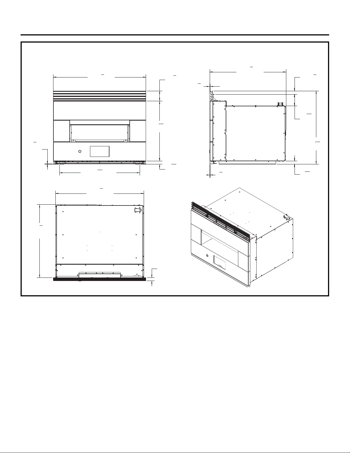
PRODUCT DIMENSIONS (WITH TRIM)
29
3
4
"
Overall At Front
1
8
"
Trim Offset
Foot To
Bottom Trim
3
1
4
"
Upper Trim
Height
19
5
16
"
Front Height
1
1
32
"
Foot to
Front Bottom
25
27
32
"
Outside Feet Overall
24
1
2
"
Overall Front
To Back Spacer
1
8
"
Trim Offset
1
8
"
Trim Offset
23
9
16
"
Foot To Top Trim
1
1
8
"
Offset To Spacer
1
1
16
"
Foot To Case Bottom
3
21
32
"
Case Top
To Spacer
28
3
8
"
Case Width
At Side Spacers
1"
Front Depth
23
1
2
"
Back Of Top Trim
To Back Spacer
31-2001053 Rev. 0 5
Design Information
PRE-INSTALLATION CHECKLIST
ALL INSTALLATION INFORMATION ON
THE FOLLOWING PAGES IS TO BE USED
FOR ELECTRIC INDOOR HEARTH OVEN
INSTALLATION!
Remove packaging materials and literature pack.
Remove Installation Instructions from literature pack
and read them carefully before you begin.
Be sure to place all literature, Owner’s Manual,
Installations, etc. in a safe place for future reference.
Place the oven on a table or platform even
with the cutout opening. Platform must support
200 lbs. (91 Kg).
The Hearth Oven may be installed in a cabinet
alone, above or next to approved models. See label
on top of the oven for approved models or go to
geappliances.com/combinations.
CAUTION
Installing the oven below the
minimum height of 45 inches creates a burn
hazard for children. Do not install below the
minimum height.
Literature Pack
Included Trim
Hearth Oven
Be
f
ore you be
gin
-
R
e
a
d
t
h
e
s
e
in
s
t
ru
c
t
io
ns
c
o
m
ple
te
l
y
a
n
d
c
a
re
fully
.
IM
PO
RT
AN
T-
Sa
ve
t
he
s
e
i
n
s
t
ru
ct
io
n
s
f
o
r
l
o
ca
l
in
sp
e
c
t
or'
s
us
e
.
I
M
PO
RT
AN
T-
O
B
SE
R
V
E
A
L
L
GO
VE
RN
I
N
G CO
DE
S
AN
D
OR
DI
AN
C
E
S.
No
te
t
o
Inst
a
l
l
e
r-
B
e
su
re
to
le
a
v
e
these i
n
st
r
u
ct
io
n
s
w
i
t
h
th
e co
ns
u
me
r.
O
W
NE
R-
Ke
e
p
th
e
s
e
in
st
r
u
c
t
io
ns
fo
r
futu
re
re
fe
re
nc
e.
N
o
te
-
Th
is
a
ppl
i
an
ce
mu
st
be
p
roper
ly
g
rou
nd
ed
(
i
f
a
p
plic
a
ble
).
Be
f
ore yo
u
be
gin-
Re
ad
t
h
ese
in
s
t
ru
c
t
ion
s
c
o
mp
le
t
e
ly
an
d
ca
re
ful
ly
.
I
M
PO
RTA
N
T-
Sa
ve
th
es
e
in
st
ru
c
t
io
n
s
f
o
r
lo
ca
l
in
sp
e
c
t
or
'
s
us
e
.
IM
PO
RT
AN
T-
OB
S
ERVE
ALL
GO
V
E
RN
IN
G
C
O
DE
S
AN
D
O
R
D
I
AN
CE
S.
No
te
to
Inst
a
l
le
r-
B
e
s
u
r
e
to
le
av
e
th
es
e in
st
ru
ct
i
o
ns
wi
th
th
e
co
ns
u
mer
.
O
W
NE
R
-
Ke
ep
the
s
e
i
n
st
ru
c
t
i
o
ns
f
or f
u
tu
re
re
fe
r
enc
e.
No
te-
This
a
ppli
a
n
ce
mus
t
b
e
pr
o
pe
r
ly
g
rou
nd
e
d
(
i
f
a
ppl
i
c
a
ble
).
FO
R
YO
U
R
S
A
FE
T
Y
Be
f
ore
you
b
e
gin
-
Re
a
d
th
e
s
e in
s
t
ru
c
t
io
ns
c
o
m
ple
te
ly
a
n
d
c
a
re
fully
.
IM
PO
RT
AN
T-
Sa
ve
t
hes
e
i
n
s
t
ru
ctio
n
s
fo
r
lo
c
a
l
in
sp
e
c
t
o
r
'
s
us
e.
I
M
PO
RT
AN
T-
O
B
SER
VE
A
L
L
GO
V
E
RN
I
N
G
CO
DE
S
AN
D
O
R
DI
AN
C
E
S.
No
te
to
In
st
a
l
le
r
-
B
e
su
re to
le
av
e th
es
e
i
n
st
r
u
ctio
n
s
w
i
th
th
e
c
o
ns
u
me
r.
OW
NER-
Ke
e
p
th
es
e
in
st
r
u
c
t
io
ns
fo
r
futu
re
re
fe
renc
e.
N
o
te
-
Thi
s
a
p
pl
i
a
n
ce
mu
st
be
p
rop
e
rly
g
rou
nd
ed
(if
a
pplic
ab
le
).
Be
f
ore
you
be
gin
-
Re
a
d
t
h
e
s
e
in
s
t
ru
c
t
io
ns
c
o
m
ple
te
ly
a
n
d
ca
re
fully
.
IM
PO
RT
AN
T-
Sa
ve
th
es
e
i
n
st
ru
ctio
n
s
fo
r
lo
c
a
l
in
s
p
e
c
t
or'
s
us
e
.
I
M
PO
RT
AN
T
-
O
B
SERV
E
A
LL
GO
VE
RN
I
N
G C
O
DE
S
AN
D
OR
DI
AN
CE
S.
N
o
te
to
In
st
al
le
r-
B
e
su
r
e
to
le
a
v
e
th
es
e i
n
st
r
u
ction
s
w
i
th
th
e
co
ns
u
me
r
.
OW
NE
R-
Ke
e
p
th
e
s
e
in
st
ru
c
t
io
ns
fo
r
futu
re refe
renc
e.
N
o
t
e
-
Thi
s
appl
i
a
n
ce
must
be
p
roper
ly
g
rou
nd
e
d
(if
a
pplic
a
ble
).
EL
EC
TRI
C
AL
RE
QU
IR
EM
EN
T
S
B
e
f
ore y
o
u
be
gin-
Re
ad
th
es
e
i
n
s
t
ru
ctions
co
mp
le
t
e
ly
an
d
ca
r
e
f
u
l
ly
.
I
M
PO
RT
AN
T
-
S
a
ve
th
es
e
i
ns
t
ru
ct
io
ns
fo
r
lo
c
a
l
in
s
pec
t
or'
s
us
e.
IM
PO
RTAN
T
-
OB
SERV
E
A
L
L
GO
VE
RN
IN
G
CO
D
E
S
AN
D
OR
DI
AN
C
E
S.
No
te
t
o
I
n
st
alle
r-
Be
su
re to
le
a
v
e
th
es
e
in
st
ru
c
t
io
ns
wi
th
th
e
c
o
n
s
u
mer
.
O
W
N
E
R-
K
eep
thes
e
in
st
ru
ctio
n
s
fo
r
f
u
tu
re refe
r
en
c
e.
No
te-
Th
is
a
p
plia
nc
e
mu
st
be
prop
er
ly
g
round
ed
(i
f
a
ppl
i
ca
ble
).
B
e
f
or
e
you
be
g
i
n-
Re
a
d
th
es
e
in
st
ru
c
t
io
ns
c
o
mp
le
te
ly
an
d
c
a
re
f
u
l
l
y
.
IM
PO
R
T
A
N
T-
Sa
ve
th
e
s
e
i
n
st
ru
c
t
io
ns
fo
r
lo
ca
l
i
n
sp
e
c
t
or'
s
us
e.
IM
PO
RT
A
N
T
-
O
B
SERV
E
A
L
L
GO
VE
RN
I
N
G CO
DE
S
AN
D
OR
D
I
AN
CE
S.
N
o
te
to
In
st
a
l
le
r-
Be
su
re to
le
a
v
e
th
es
e
in
st
r
u
c
t
ion
s
w
i
th
t
h
e co
ns
u
me
r.
OW
NE
R
-
K
e
ep
th
e
s
e
in
s
t
ru
cti
o
ns
f
or
futu
re r
e
f
e
rence
.
No
te
-
Thi
s
a
p
pli
an
ce
mu
st
be
prop
e
r
ly
g
r
ound
e
d
(if
a
p
pli
ca
bl
e
).
B
e
f
or
e
yo
u be
gin
-
Re
a
d
th
e
s
e
in
st
r
u
c
t
io
ns
co
mp
l
e
te
ly
an
d
c
a
re
fully
.
IM
PO
RT
AN
T
-
Sa
ve
th
es
e
in
st
ru
c
t
io
ns
f
o
r
l
o
ca
l
in
sp
e
c
t
or'
s
us
e.
I
M
PO
RT
A
N
T
-
OB
SERV
E
A
LL
G
O
VE
RN
I
N
G
CO
D
E
S
A
N
D
O
R
DI
AN
CE
S.
No
t
e
to
I
n
s
t
al
le
r-
B
e
su
r
e
to
l
e
av
e
th
ese i
n
st
ru
ctio
n
s
wi
t
h
th
e
c
o
ns
u
me
r.
OW
NER
-
K
eep
t
h
e
s
e
i
n
s
t
ru
c
ti
o
ns
f
or
futu
re ref
e
renc
e.
No
te
-
Th
i
s
a
ppli
an
ce
mus
t
b
e
prop
e
rly
g
rounde
d
(if
a
ppli
c
a
ble
).
Be
f
ore you be
gin
-
Re
ad
th
e
s
e
inst
ru
c
t
io
ns
c
om
ple
tely
a
n
d
ca
re
fully
.
IM
PO
RT
AN
T-
Sa
ve
th
ese i
n
st
ru
ct
io
n
s
fo
r
lo
c
a
l
in
s
p
e
c
t
or'
s
us
e
.
I
M
PO
RT
AN
T
-
O
B
SERV
E
A
LL
GOV
E
RN
I
N
G
C
O
DE
S
AN
D
O
R
DI
AN
CES.
No
te
to
Inst
a
l
le
r-
B
e
su
re to
le
av
e
th
es
e
i
n
st
ru
ction
s
w
i
t
h
th
e co
ns
u
me
r
.
OW
NE
R-
Ke
e
p
th
e
s
e
in
st
ru
c
t
io
ns
fo
r
futu
re
re
fe
re
nc
e.
N
o
te
-
Th
i
s
a
ppl
i
a
n
ce
mu
st
be
p
rop
e
r
ly
g
ro
u
nd
e
d
(if
a
pplic
ab
le
).
Be
f
ore yo
u
be
gin-
Re
ad
t
h
ese
in
s
t
ru
c
t
ion
s
c
o
mp
le
t
e
ly
an
d
ca
re
ful
ly
.
I
M
PO
RTA
N
T-
Sa
ve
th
es
e
in
st
ru
c
t
io
n
s
f
o
r
lo
ca
l
in
sp
e
c
t
or
'
s
us
e
.
IM
PO
RT
AN
T-
OB
S
ERVE
ALL
GO
V
E
RN
IN
G
C
O
DE
S
AN
D
O
R
D
I
AN
CE
S.
No
te
to
Inst
a
l
le
r-
B
e
s
u
r
e
to
le
av
e
th
es
e in
st
ru
ct
i
o
ns
wi
th
th
e
co
ns
u
mer
.
O
W
NE
R
-
Ke
ep
the
s
e
i
n
st
ru
c
t
i
o
ns
f
or f
u
tu
re
re
fe
r
enc
e.
No
te-
This
a
ppli
a
n
ce
mus
t
b
e
pr
o
pe
r
ly
g
rou
nd
e
d
(
i
f
a
ppl
i
c
a
ble
).
FO
R
YO
U
R
S
A
FE
T
Y
Be
f
ore
you
b
e
gin
-
Re
a
d
th
e
s
e in
s
t
ru
c
t
io
ns
c
o
m
ple
te
ly
a
n
d
c
a
re
fully
.
IM
PO
RT
AN
T-
Sa
ve
t
hes
e
i
n
s
t
ru
ctio
n
s
fo
r
lo
c
a
l
in
sp
e
c
t
o
r
'
s
us
e.
I
M
PO
RT
AN
T-
O
B
SER
VE
A
L
L
GO
V
E
RN
I
N
G
CO
DE
S
AN
D
O
R
DI
AN
C
E
S.
No
te
to
In
st
a
l
le
r
-
B
e
su
re to
le
av
e th
es
e
i
n
st
r
u
ctio
n
s
w
i
th
th
e
c
o
ns
u
me
r.
OW
NER-
Ke
e
p
th
es
e
in
st
r
u
c
t
io
ns
fo
r
futu
re
re
fe
renc
e.
N
o
te
-
Thi
s
a
p
pl
i
a
n
ce
mu
st
be
p
rop
e
rly
g
rou
nd
ed
(if
a
pplic
ab
le
).
Be
f
ore
you
be
gin
-
Re
a
d
t
h
e
s
e
in
s
t
ru
c
t
io
ns
c
o
m
ple
te
ly
a
n
d
ca
re
fully
.
IM
PO
RT
AN
T-
Sa
ve
th
es
e
i
n
st
ru
ctio
n
s
fo
r
lo
c
a
l
in
s
p
e
c
t
or'
s
us
e
.
I
M
PO
RT
AN
T
-
O
B
SERV
E
A
LL
GO
VE
RN
I
N
G C
O
DE
S
AN
D
OR
DI
AN
CE
S.
N
o
te
to
In
st
al
le
r-
B
e
su
r
e
to
le
a
v
e
th
es
e i
n
st
r
u
ction
s
w
i
th
th
e
co
ns
u
me
r
.
OW
NE
R-
Ke
e
p
th
e
s
e
in
st
ru
c
t
io
ns
fo
r
futu
re refe
renc
e.
N
o
t
e
-
Thi
s
appl
i
a
n
ce
must
be
p
roper
ly
g
rou
nd
e
d
(if
a
pplic
a
ble
).
EL
EC
TRI
C
AL
RE
QU
IR
EM
EN
T
S
B
e
f
ore y
o
u
be
gin-
Re
ad
th
es
e
i
n
s
t
ru
ctions
co
mp
le
t
e
ly
an
d
ca
r
e
f
u
l
ly
.
I
M
PO
RT
AN
T
-
S
a
ve
th
es
e
i
ns
t
ru
ct
io
ns
fo
r
lo
c
a
l
in
s
pec
t
or'
s
us
e.
IM
PO
RTAN
T
-
OB
SERV
E
A
L
L
GO
VE
RN
IN
G
CO
D
E
S
AN
D
OR
DI
AN
C
E
S.
No
te
t
o
I
n
st
alle
r-
Be
su
re to
le
a
v
e
th
es
e
in
st
ru
c
t
io
ns
wi
th
th
e
c
o
n
s
u
mer
.
O
W
N
E
R-
K
eep
thes
e
in
st
ru
ctio
n
s
fo
r
f
u
tu
re refe
r
en
c
e.
No
te-
Th
is
a
p
plia
nc
e
mu
st
be
prop
er
ly
g
round
ed
(i
f
a
ppl
i
ca
ble
).
B
e
f
or
e
you
be
g
i
n-
Re
a
d
th
es
e
in
st
ru
c
t
io
ns
c
o
mp
le
te
ly
an
d
c
a
re
f
u
l
l
y
.
IM
PO
R
T
A
N
T-
Sa
ve
th
e
s
e
i
n
st
ru
c
t
io
ns
fo
r
lo
ca
l
i
n
sp
e
c
t
or'
s
us
e.
IM
PO
RT
A
N
T
-
O
B
SERV
E
A
L
L
GO
VE
RN
I
N
G CO
DE
S
AN
D
OR
D
I
AN
CE
S.
N
o
te
to
In
st
a
l
le
r-
Be
su
re to
le
a
v
e
th
es
e
in
st
r
u
c
t
ion
s
w
i
th
t
h
e co
ns
u
me
r.
OW
NE
R
-
K
e
ep
th
e
s
e
in
s
t
ru
cti
o
ns
f
or
futu
re r
e
f
e
rence
.
No
te
-
Thi
s
a
p
pli
an
ce
mu
st
be
prop
e
r
ly
g
r
ound
e
d
(if
a
p
pli
ca
bl
e
).
B
e
f
or
e
yo
u be
gin
-
Re
a
d
th
e
s
e
in
st
r
u
c
t
io
ns
co
mp
l
e
te
ly
an
d
c
a
re
fully
.
IM
PO
RT
AN
T
-
Sa
ve
th
es
e
in
st
ru
c
t
io
ns
f
o
r
l
o
ca
l
in
sp
e
c
t
or'
s
us
e.
I
M
PO
RT
A
N
T
-
OB
SERV
E
A
LL
G
O
VE
RN
I
N
G
CO
D
E
S
A
N
D
O
R
DI
AN
CE
S.
No
t
e
to
I
n
s
t
al
le
r-
B
e
su
r
e
to
l
e
av
e
th
ese i
n
st
ru
ctio
n
s
wi
t
h
th
e
c
o
ns
u
me
r.
OW
NER
-
K
eep
t
h
e
s
e
i
n
s
t
ru
c
ti
o
ns
f
or
futu
re ref
e
renc
e.
No
te
-
Th
i
s
a
ppli
an
ce
mus
t
b
e
prop
e
rly
g
rounde
d
(if
a
ppli
c
a
ble
).
Be
f
ore you be
gin
-
R
e
a
d
t
h
e
s
e
in
s
t
ru
c
t
io
ns
c
o
m
ple
te
l
y
a
n
d
c
a
re
fully
.
IM
PO
RT
AN
T-
Sa
ve
t
he
s
e
i
n
s
t
ru
ct
io
n
s
f
o
r
l
o
ca
l
in
sp
e
c
t
or'
s
us
e
.
I
M
PO
RT
AN
T-
O
B
SE
R
V
E
A
L
L
GO
VE
RN
I
N
G CO
DE
S
AN
D
OR
DI
AN
C
E
S.
No
te
t
o
Inst
a
l
l
e
r-
B
e
su
re
to
le
a
v
e
these i
n
st
r
u
ct
io
n
s
w
i
t
h
th
e co
ns
u
me
r.
O
W
NE
R-
Ke
e
p
th
e
s
e
in
st
r
u
c
t
io
ns
fo
r
futu
re
re
fe
re
nc
e.
N
o
te
-
Th
is
a
ppl
i
an
ce
mu
st
be
p
roper
ly
g
rou
nd
ed
(
i
f
a
p
plic
a
ble
).
Be
f
ore yo
u
be
gin-
Re
ad
t
h
ese
in
s
t
ru
c
t
ion
s
c
o
mp
le
t
e
ly
an
d
ca
re
ful
ly
.
I
M
PO
RTA
N
T-
Sa
ve
th
es
e
in
st
ru
c
t
io
n
s
f
o
r
lo
ca
l
in
sp
e
c
t
or
'
s
us
e
.
IM
PO
RT
AN
T-
OB
S
ERVE
ALL
GO
V
E
RN
IN
G
C
O
DE
S
AN
D
O
R
D
I
AN
CE
S.
No
te
to
Inst
a
l
le
r-
B
e
s
u
r
e
to
le
av
e
th
es
e in
st
ru
ct
i
o
ns
wi
th
th
e
co
ns
u
mer
.
O
W
NE
R
-
Ke
ep
the
s
e
i
n
st
ru
c
t
i
o
ns
f
or f
u
tu
re
re
fe
r
enc
e.
No
te-
This
a
ppli
a
n
ce
mus
t
b
e
pr
o
pe
r
ly
g
rou
nd
e
d
(
i
f
a
ppl
i
c
a
ble
).
FO
R
YO
U
R
S
A
FE
T
Y
Be
f
ore
you
b
e
gin
-
Re
a
d
th
e
s
e in
s
t
ru
c
t
io
ns
c
o
m
ple
te
ly
a
n
d
c
a
re
fully
.
IM
PO
RT
AN
T-
Sa
ve
t
hes
e
i
n
s
t
ru
ctio
n
s
fo
r
lo
c
a
l
in
sp
e
c
t
o
r
'
s
us
e.
I
M
PO
RT
AN
T-
O
B
SER
VE
A
L
L
GO
V
E
RN
I
N
G
CO
DE
S
AN
D
O
R
DI
AN
C
E
S.
No
te
to
In
st
a
l
le
r
-
B
e
su
re to
le
av
e th
es
e
i
n
st
r
u
ctio
n
s
w
i
th
th
e
c
o
ns
u
me
r.
OW
NER-
Ke
e
p
th
es
e
in
st
r
u
c
t
io
ns
fo
r
futu
re
re
fe
renc
e.
N
o
te
-
Thi
s
a
p
pl
i
a
n
ce
mu
st
be
p
rop
e
rly
g
rou
nd
ed
(if
a
pplic
ab
le
).
Be
f
ore
you
be
gin
-
Re
a
d
t
h
e
s
e
in
s
t
ru
c
t
io
ns
c
o
m
ple
te
ly
a
n
d
ca
re
fully
.
IM
PO
RT
AN
T-
Sa
ve
th
es
e
i
n
st
ru
ctio
n
s
fo
r
lo
c
a
l
in
s
p
e
c
t
or'
s
us
e
.
I
M
PO
RT
AN
T
-
O
B
SERV
E
A
LL
GO
VE
RN
I
N
G C
O
DE
S
AN
D
OR
DI
AN
CE
S.
N
o
te
to
In
st
al
le
r-
B
e
su
r
e
to
le
a
v
e
th
es
e i
n
st
r
u
ction
s
w
i
th
th
e
co
ns
u
me
r
.
OW
NE
R-
Ke
e
p
th
e
s
e
in
st
ru
c
t
io
ns
fo
r
futu
re refe
renc
e.
N
o
t
e
-
Thi
s
appl
i
a
n
ce
must
be
p
roper
ly
g
rou
nd
e
d
(if
a
pplic
a
ble
).
EL
EC
TRI
C
AL
RE
QU
IR
EM
EN
T
S
B
e
f
ore y
o
u
be
gin-
Re
ad
th
es
e
i
n
s
t
ru
ctions
co
mp
le
t
e
ly
an
d
ca
r
e
f
u
l
ly
.
I
M
PO
RT
AN
T
-
S
a
ve
th
es
e
i
ns
t
ru
ct
io
ns
fo
r
lo
c
a
l
in
s
pec
t
or'
s
us
e.
IM
PO
RTAN
T
-
OB
SERV
E
A
L
L
GO
VE
RN
IN
G
CO
D
E
S
AN
D
OR
DI
AN
C
E
S.
No
te
t
o
I
n
st
alle
r-
Be
su
re to
le
a
v
e
th
es
e
in
st
ru
c
t
io
ns
wi
th
th
e
c
o
n
s
u
mer
.
O
W
N
E
R-
K
eep
thes
e
in
st
ru
ctio
n
s
fo
r
f
u
tu
re refe
r
en
c
e.
No
te-
Th
is
a
p
plia
nc
e
mu
st
be
prop
er
ly
g
round
ed
(i
f
a
ppl
i
ca
ble
).
B
e
f
or
e
you
be
g
i
n-
Re
a
d
th
es
e
in
st
ru
c
t
io
ns
c
o
mp
le
te
ly
an
d
c
a
re
f
u
l
l
y
.
IM
PO
R
T
A
N
T-
Sa
ve
th
e
s
e
i
n
st
ru
c
t
io
ns
fo
r
lo
ca
l
i
n
sp
e
c
t
or'
s
us
e.
IM
PO
RT
A
N
T
-
O
B
SERV
E
A
L
L
GO
VE
RN
I
N
G CO
DE
S
AN
D
OR
D
I
AN
CE
S.
N
o
te
to
In
st
a
l
le
r-
Be
su
re to
le
a
v
e
th
es
e
in
st
r
u
c
t
ion
s
w
i
th
t
h
e co
ns
u
me
r.
OW
NE
R
-
K
e
ep
th
e
s
e
in
s
t
ru
cti
o
ns
f
or
futu
re r
e
f
e
rence
.
No
te
-
Thi
s
a
p
pli
an
ce
mu
st
be
prop
e
r
ly
g
r
ound
e
d
(if
a
p
pli
ca
bl
e
).
B
e
f
or
e
yo
u be
gin
-
Re
a
d
th
e
s
e
in
st
r
u
c
t
io
ns
co
mp
l
e
te
ly
an
d
c
a
re
fully
.
IM
PO
RT
AN
T
-
Sa
ve
th
es
e
in
st
ru
c
t
io
ns
f
o
r
l
o
ca
l
in
sp
e
c
t
or'
s
us
e.
I
M
PO
RT
A
N
T
-
OB
SERV
E
A
LL
G
O
VE
RN
I
N
G
CO
D
E
S
A
N
D
O
R
DI
AN
CE
S.
No
t
e
to
I
n
s
t
al
le
r-
B
e
su
r
e
to
l
e
av
e
th
ese i
n
st
ru
ctio
n
s
wi
t
h
th
e
c
o
ns
u
me
r.
OW
NER
-
K
eep
t
h
e
s
e
i
n
s
t
ru
c
ti
o
ns
f
or
futu
re ref
e
renc
e.
No
te
-
Th
i
s
a
ppli
an
ce
mus
t
b
e
prop
e
rly
g
rounde
d
(if
a
ppli
c
a
ble
).
Installation
Instructions
BEFORE YOU BEGIN
Read these instructions carefully and completely.
•
IMPORTANT — Save these instructions
for local inspector’s use.
•
IMPORTANT — Observe all governing
codes and ordinances.
• Note to Installer – Be sure to leave these
instructions with the consumer.
• Note to Consumer – Keep these instructions for
future reference.
• Proper installation is the responsibility of the
installer and product failure due to improper
installation is NOT covered under warranty.
• Note – This appliance must be properly grounded.
•
ATTENTION INSTALLER
All electric wall ovens must be hard wired (direct
wired) into an approved junction box. A plug and
receptacle is NOT permitted on these products.
Indoor Hearth Oven
ZEP30
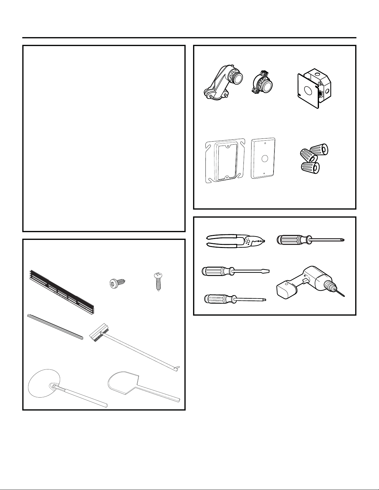
MATERIALS NEEDED
TOOLS NEEDED
TRIM KIT PARTS
(Included with ZEP30F)
PARTS INCLUDED
(Appearance will vary)
If you have questions, call GE Appliances at 800.GE.CARES (800.432.2737)
or visit our website at: GEAppliances.com.
31-11062 Rev. 3 03-19 GEA
Strain Relief Clamp
for 1/2” conduit
Plaster Ring
(Option 1)
Wire Strippers
3/4” Phillips
Screws (4)
Side Trim
Junction Box
(1 1/2 Depth Max.)
Phillips #2
Screwdriver
Flathead
Screwdriver
Drill and 3/32” drill bit
Wire Nuts
Brush
Option 1
Option 2
Metal Peel
Wooden Peel
1” Drywall Screw
5/8” Phillips
Case Screw
Tether
Top Grille
Bottom Grille
6 31-2001053 Rev. 0
Installation Information
BEFORE YOU BEGIN
Read these instructions carefully and completely.
• IMPORTANT — Save these instructions
for local inspector’s use.
• IMPORTANT — Observe all governing
codes and ordinances.
• Note to Installer – Be sure to leave these
instructions with the consumer.
• Note to Consumer – Keep these instructions for
future reference.
• Proper installation is the responsibility of the installer
and product failure due to improper installation is
NOT covered under warranty.
• Note – This appliance must be properly grounded.
• ATTENTION INSTALLER
All electric wall ovens must be hard wired (direct
wired) into an approved junction box. A plug and
receptacle is NOT permitted on these products.
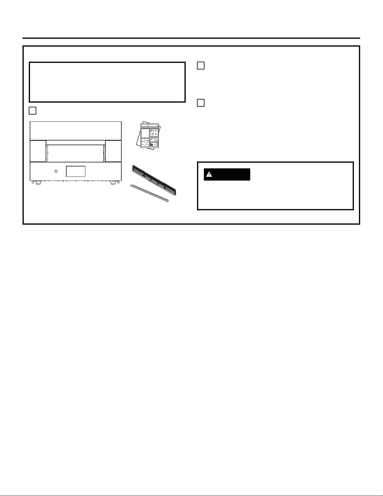
PARTS INCLUDED
(Appearance will vary)
Brush
Metal Peel
Top Grille
Assembly
Bottom
Grille
Wooden Peel
Upper &
Lower Grille
1/2” T20 Torx
(8)
3/4” Phillips
Screws (2)
MATERIALS NEEDED
TOOLS NEEDED
Strain Relief Clamp
for 1/2” conduit
Plaster Ring and Cover
(Option 1)
Wire Strippers
Junction Box
(1 1/2 Depth Max.)
Phillips #2
Screwdriver
Flathead
Screwdriver
T20 Torx Screwdriver
Drill and 3/32” drill bit
Wire Nuts
Option 1
Option 2
31-2001053 Rev. 0 7
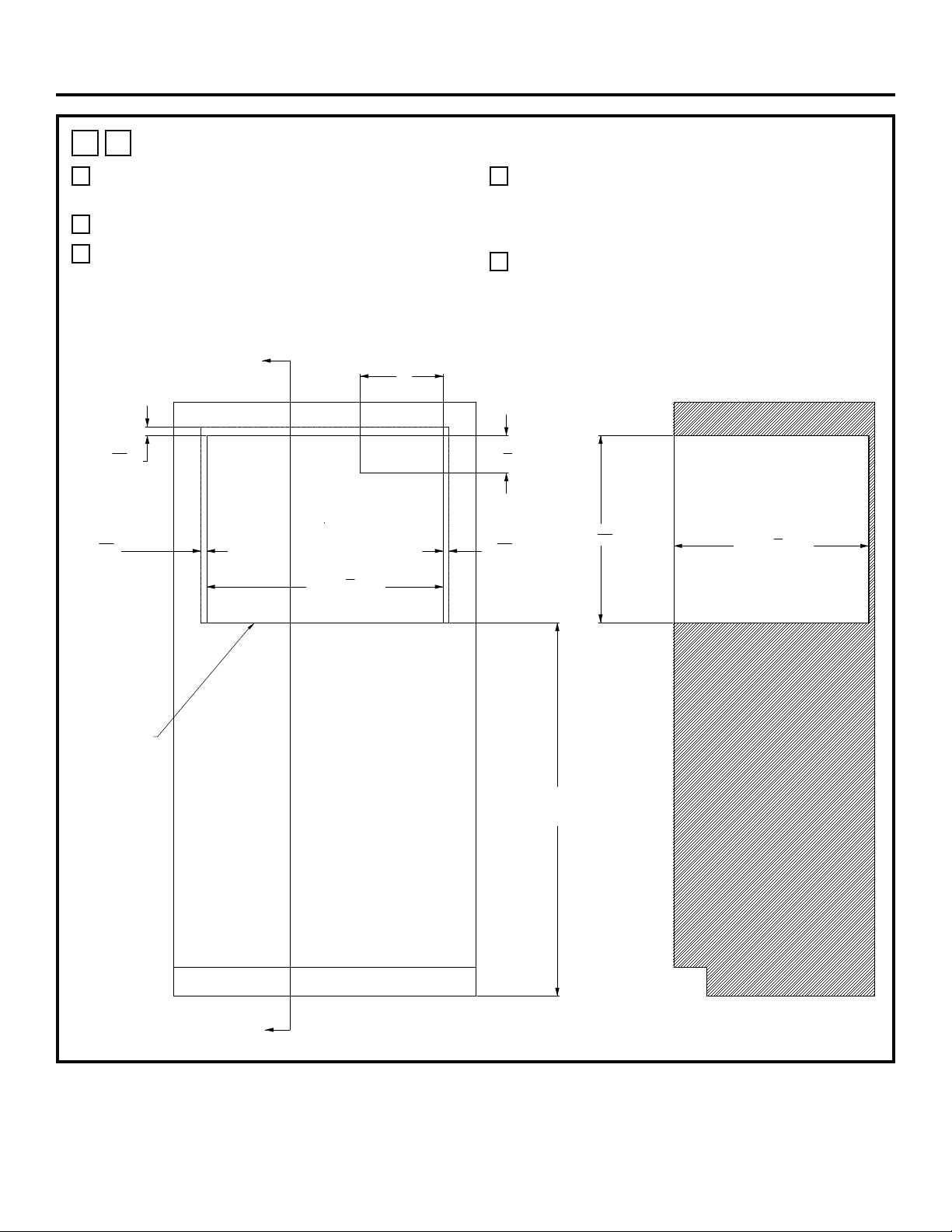
Installations
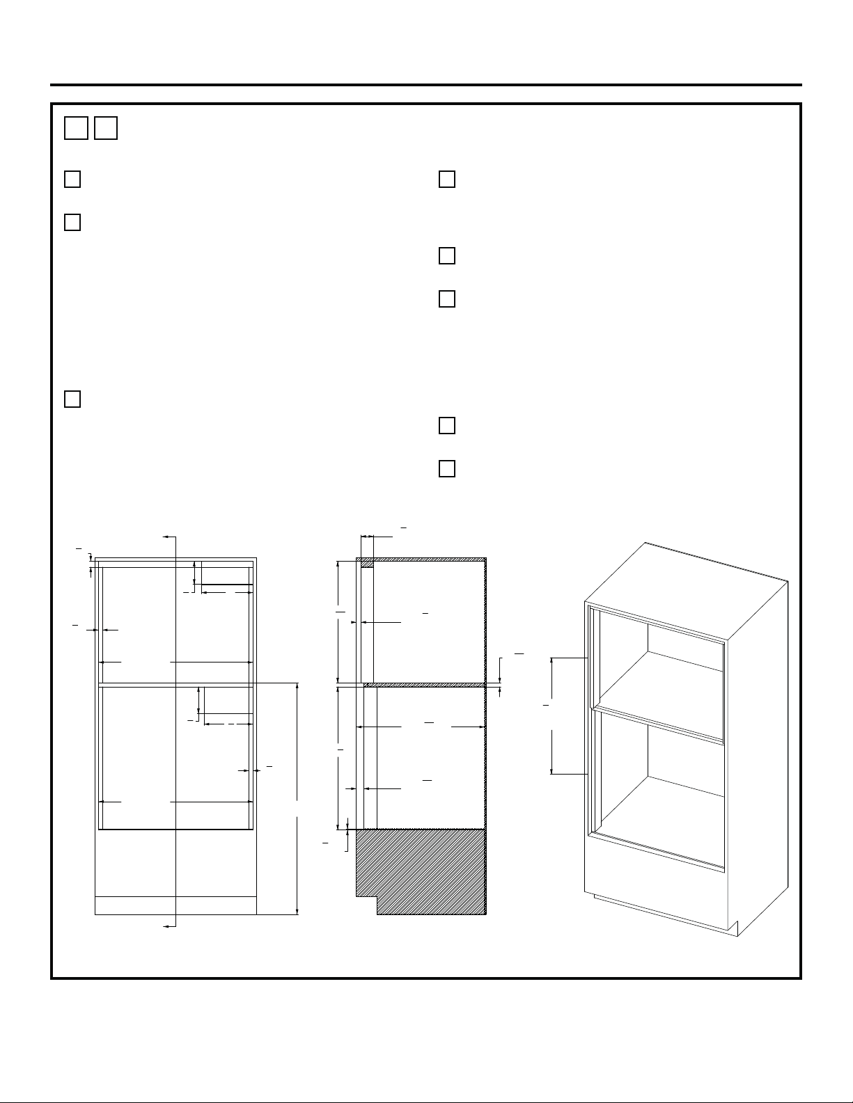
1
A
HEARTH OVEN - STANDARD INSTALLATION
A
45” is the required minimum installation height. Oven
may be installed higher based on owner preference.
B
Platform must be able to support 200 lbs (91 kg).
C
Solid enclosure required on the top, bottom, left
side, right side and back. The back surface may
be drywall. Advanced fabrication and assembly
techniques are strongly encouraged to ensure
precise cabinet squareness and parallelism.
D
Junction box location: Must be flush with back
surface so as not to extend into the 23 ½ inch
cabinet depth. Junction box may also be located in
an adjacent cabinet.
E
A flush appearance my be achieved relative to
surrounding cabinet door and drawer fronts. A
minimum 1/8” reveal BEYOND the OVERLAP
dimensions is recommended.
ELEC
10"
4
1
2
"
11
16
"
OVERLAP
1
1
16
"
OVERLAP
11
16
"
OVERLAP
45"
MINIMUM FLOOR
TO OVEN PLATFORM
A
A
SECTION A-A
28
1
2
"
CUTOUT WIDTH
NO BOTTOM
OVEN OVERLAP
22
9
16
"
23
1
2
"
CABINET DEPTH
SEE NOTE D
8 31-2001053 Rev. 0
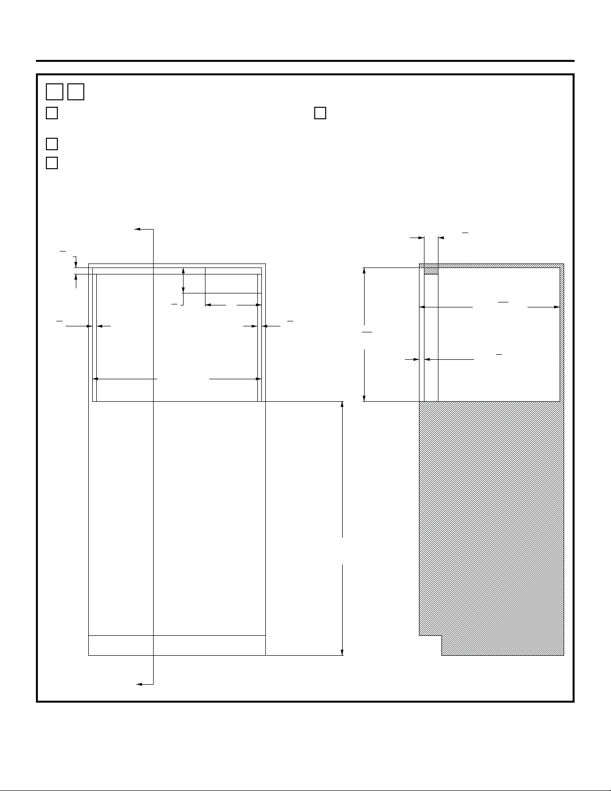
Installations
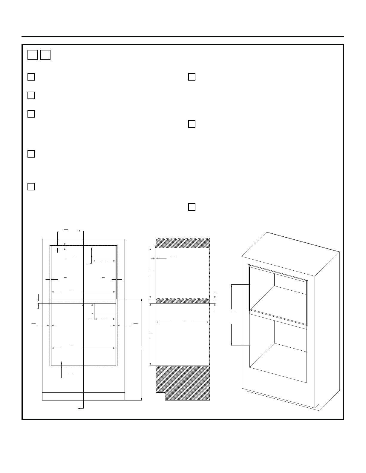
1
B
HEARTH OVEN - FLUSH INSET INSTALLATION
A
45” is the required minimum installation height. Oven
may be installed higher based on owner preference.
B
Platform must be able to support 200 lbs (91 kg).
C
Solid enclosure required on the top, bottom, left
side, right side and back. The back surface may
be drywall. Advanced fabrication and assembly
techniques are strongly encouraged to ensure
precise cabinet squareness and parallelism.
D
Junction box location: Must be flush with back
surface so as not to extend into the 24-15/16”
cabinet depth. Junction box may also be located in
an adjacent cabinet.
ELEC
B
B
SECTION B-B
10"
4
1
2
"
45"
MINIMUM FLOOR
TO OVEN PLATFORM
30"
CUT OUT WIDTH
1
1
8
"
CLEAT
3
4
"
CLEAT
3
4
"
CLEAT
23
11
16
"
CUT OUT HEIGHT
24
15
16
"
CABINET DEPTH
7
8
"
CLEAT SETBACK
2
1
2
"
CLEAT DEPTH
SEE NOTE D
31-2001053 Rev. 0 9
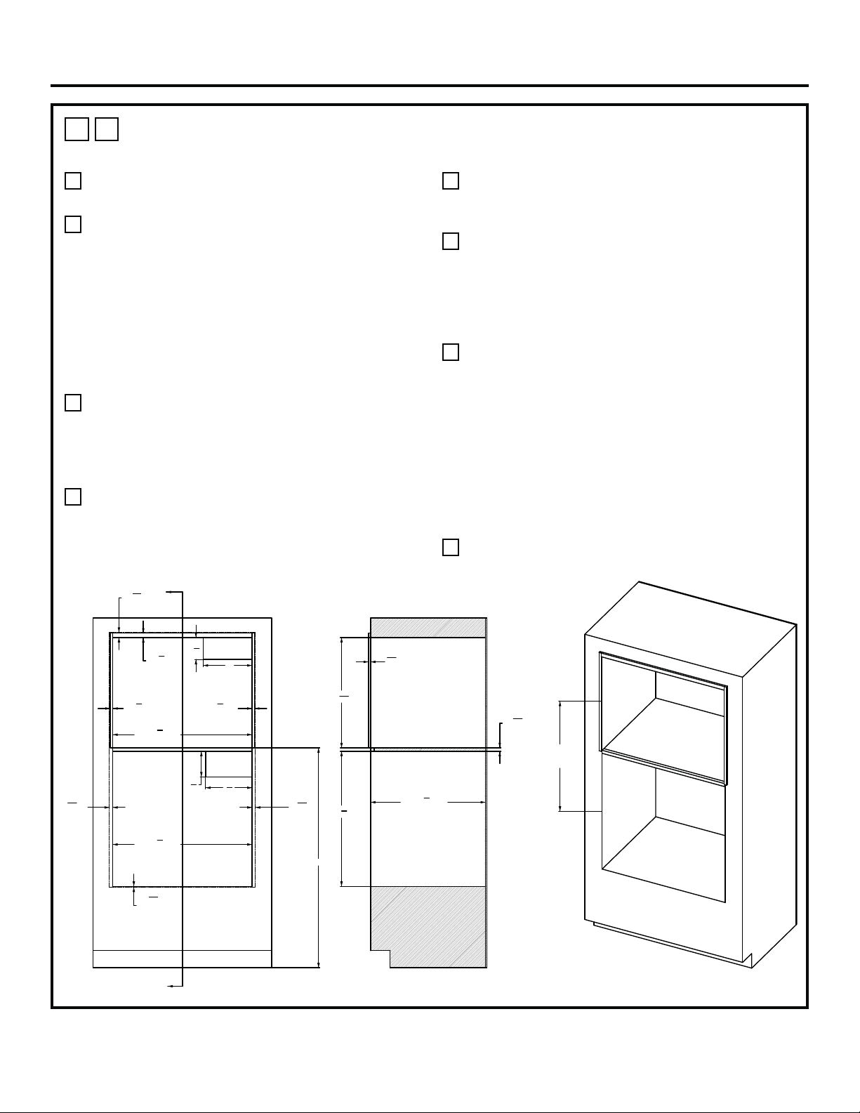
Installations
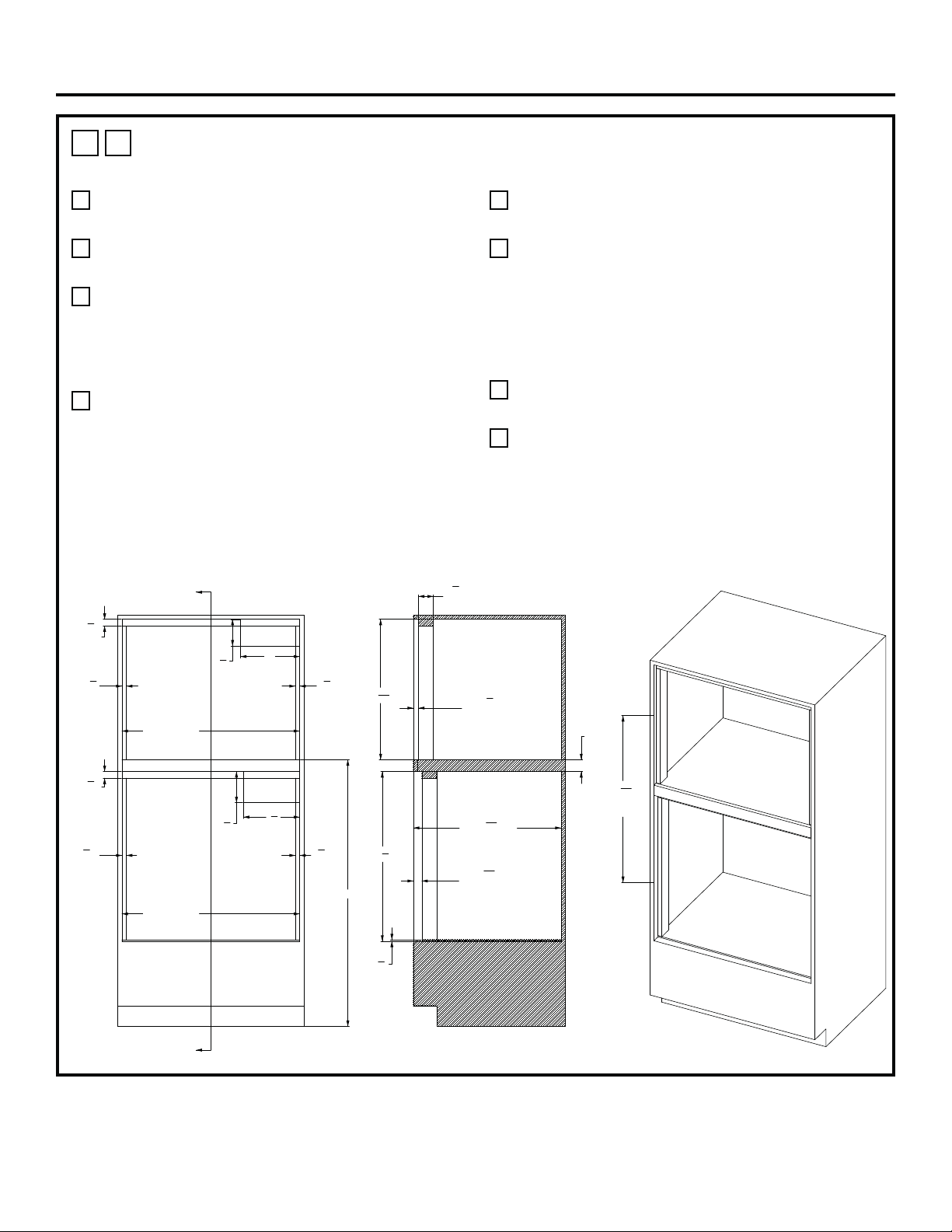
1
C
HEARTH OVEN OVER WALL OVEN –STANDARD INSTALLATION WITH A
MINIMUM GAP BETWEEN
A
45” is the required minimum installation height. Oven
may be installed higher based on owner preference.
B
Hearth Oven Platform must be able to support
200 lbs. (91kg). For this installation, it is highly
recommended to lock the platform into the side
walls using wood joinery such as a Dado Joint.
Fasteners and wood glue are also encouraged to
further reinforce the locking wood joinery. The wood
grain of the platform shall be oriented left to right.
The front nose of the platform shall be a finished
appearance surface. See illustrations 1Q & 1R for
joinery concepts.
C
Solid enclosure required on the top, bottom, left
side, right side and back. The back surface may
be drywall. Advanced fabrication and assembly
techniques are strongly encouraged to ensure
precise cabinet squareness and parallelism.
D
Junction box location: Must be flush with back
surface so as not to extend into the 23 ½ inch
cabinet depth. Junction box may also be located in
an adjacent cabinet.
E
A minimum 1/8” reveal BEYOND the OVERLAP
dimensions is recommended for proper drawer and
door operating clearance.
F
Exterior cleats may be added to the sides and top
of the Hearth Oven opening in order to bring the
front surface of the Hearth Oven into alignment with
the front surface of the wall oven below. Finish per
customer requirements. A flat black finish may better
match the side appearance of the oven below.
G
For the LOWER WALL OVEN, an extruded
aluminum LOWER VENT TRIM is encouraged. Wall
oven models beginning with “ZTSX” already include
the aluminum vent trim. For models beginning
with “ZTS”, the vent trim kit ZX30VT1 must be
ordered which includes the aluminum vent trim and
mounting hardware. Alternatively, the stainless-steel
trim supplied with all models may be used in this
cabinet configuration. Be sure to adjust the “overlap”
dimension associated with the stainless-steel trim.
Please call 1-800-626-2000 with any questions.
H
The opening center line dimension is taken at the
FRONT OPENING of each enclosure.
ELEC
ELEC
HEARTH OVEN PLATFORM
SEE NOTE B
10"
4
1
2
"
9
1
2
"
5
1
4
"
11
16
"
OVERLAP
11
16
"
OVERLAP
1
1
16
"
OVERLAP
3
16
"
OVERLAP
SEE NOTE G
A
A
SECTION A-A
25 13/16" MIN.
C
L
TO
C
L
SEE NOTE H
28
1
2
"
CUTOUT WIDTH
28
1
2
"
CUTOUT WIDTH
45" MIN.
7
8
"
SEE NOTE F
1
2
"
SEE NOTE F
1
2
"
SEE NOTE F
22
9
16
"
27
5
8
"
23
1
2
"
CABINET DEPTH
23
32
"MIN.
"3/4 PLYWOOD"
7
16
"
SEE NOTE F
10 31-2001053 Rev. 0
Installations
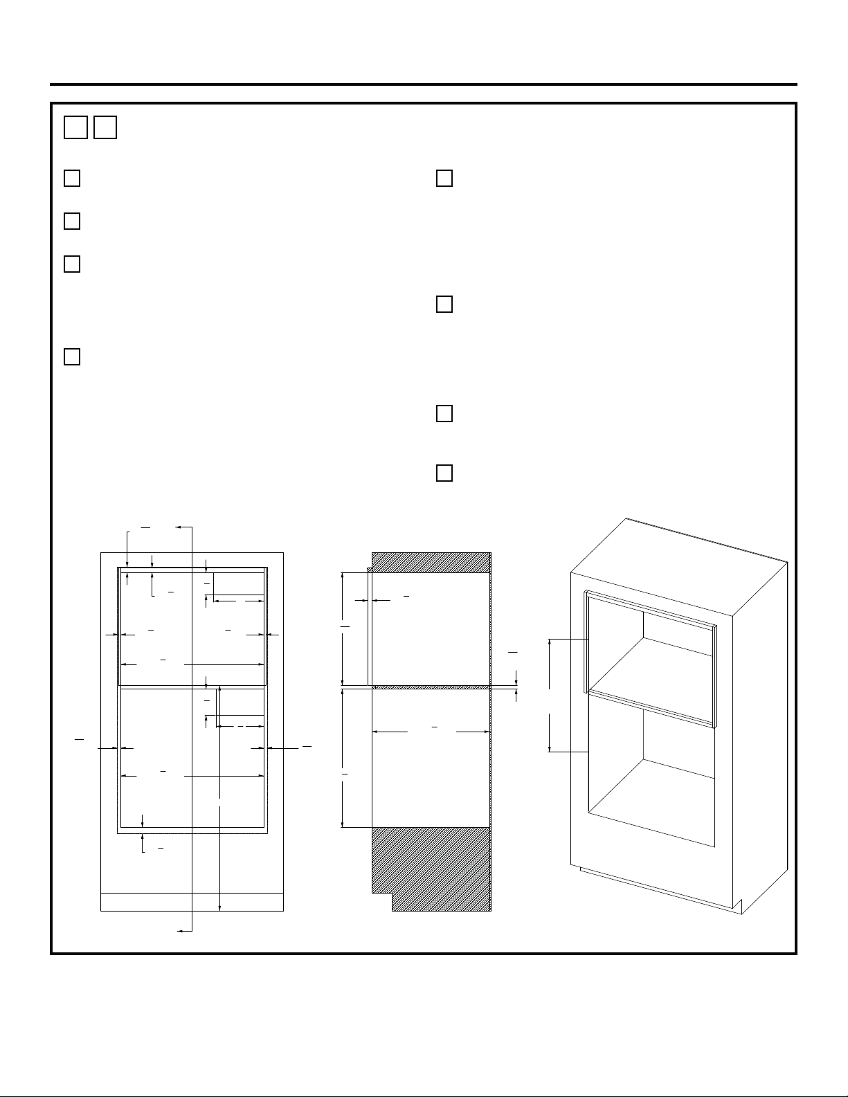
1
D
HEARTH OVEN OVER WALL OVEN – FLUSH-INSET INSTALLATION WITH A
MINIMUM GAP BETWEEN
A
45” is the required minimum installation height. Oven
may be installed higher based on owner preference.
B
Hearth Oven Platform must be able to support
200 lbs. (91kg). For this installation, it is highly
recommended to lock the platform into the side
walls using wood joinery such as a Dado Joint.
Fasteners and wood glue are also encouraged to
further reinforce the locking wood joinery. The wood
grain of the platform shall be oriented left to right.
The front nose of the platform shall be a finished
appearance surface. See illustrations 1Q & 1R for
joinery concepts.
C
Solid enclosure required on the top, bottom, left
side, right side and back. The back surface may
be drywall. Advanced fabrication and assembly
techniques are strongly encouraged to ensure
precise cabinet squareness and parallelism.
D
Junction box location: Must be flush with back
surface so as not to extend into the 24-15/16”
cabinet depth. Junction box may also be located in
an adjacent cabinet.
E
The front surface of the interior cleats shall be a
finished appearance surface.
F
The Wall Oven REQUIRES an extruded aluminum
LOWER VENT TRIM. Wall oven models beginning
with “ZTSX” already include the aluminum vent
trim. For models beginning with “ZTS”, the vent trim
kit ZX30VT1 must be ordered which includes the
aluminum vent trim and mounting hardware.
Please call 1-800-626-2000 with any questions.
G
The opening center line dimension is taken at the
FRONT OPENING of each enclosure.
H
Wall Oven bottom surface cleat is to be ¼” thick
MDF fiber board or equivalent.
26
1
2
"MIN.
C
L
TO
C
L
SEE NOTE G
ELEC.
SEE NOTE D
ELEC.
SEE NOTE D
HEARTH OVEN PLATFORM
SEE NOTE B
10"
4
1
2
"
9
1
2
"
5
1
4
"
1
1
8
"
CLEAT
3
4
"
CLEAT
3
4
"
CLEAT
30"
CUTOUT WIDTH
30"
CUTOUT WIDTH
45"
MIN
24
15
16
"
CABINET DEPTH
7
8
"
HEARTH OVEN
CLEAT SETBACK
2
1
2
"
CLEAT
DEPTH
1
7
16
"
WALL OVEN
CLEAT SETBACK
23
32
" Min.
"3/4 PLYWOOD"
1
4
"
MDF
SEE NOTE H
23
11
16
"
27
7
8
"
SECTION A-A
A
A
31-2001053 Rev. 0 11
Installations
1
E
HEARTH OVEN OVER WALL OVEN –STANDARD INSTALLATION WITH A 2”
PLATFORM BETWEEN
A
45” is the required minimum installation height. Oven
may be installed higher based on owner preference.
B
Hearth Oven Platform must be able to support
200 lbs. (91kg).
C
Solid enclosure required on the top, bottom, left
side, right side and back. The back surface may
be drywall. Advanced fabrication and assembly
techniques are strongly encouraged to ensure
precise cabinet squareness and parallelism.
D
Junction box location: Must be flush with back
surface so as not to extend into the 23 ½ inch
cabinet depth. Junction box may also be located in
an adjacent cabinet.
E
A minimum 1/8” reveal BEYOND the OVERLAP
dimensions is recommended for proper drawer and
door operating clearance.
F
Exterior cleats may be added to the sides and top
of the Hearth Oven opening in order to bring the
front surface of the Hearth Oven into alignment with
the front surface of the wall oven below. Finish per
customer requirements. A flat black finish may better
match the side appearance of the oven below.
G
For the LOWER WALL OVEN, an extruded
aluminum LOWER VENT TRIM is encouraged. Wall
oven models beginning with “ZTSX” already include
the aluminum vent trim. For models beginning
with “ZTS”, the vent trim kit ZX30VT1 must be
ordered which includes the aluminum vent trim and
mounting hardware. Alternatively, the stainless-steel
trim supplied with all models may be used in this
cabinet configuration. Be sure to adjust the “overlap”
dimension associated with the stainless-steel trim.
Please call 1-800-626-2000 with any questions.
H
The opening center line dimension is taken at the
FRONT OPENING of each enclosure.
ELEC.
SEE NOTE D
ELEC.
SEE NOTE D
HEARTH OVEN PLATFORM
SEE NOTE B
4
1
2
"
10"
5
1
4
"
9
1
2
"
1
1
16
"
OVERLAP
11
16
"
OVERLAP
3
16
"
OVERLAP
SEE NOTE G
11
16
"
OVERLAP
1"
OVERLAP
A
A
SECTION A-A
27
3
32
"
C
L
TO
C
L
SEE NOTE H
7
8
"
SEE NOTE F
28
1
2
"
CUTOUT WIDTH
1
2
"
SEE NOTE F
1
2
"
SEE NOTE F
28
1
2
"
CUTOUT WIDTH
45" MIN
22
9
16
"
7
16
"
SEE NOTE F
2"
BETWEEN
CUTOUTS
27
5
8
"
23
1
2
"
CABINET DEPTH
12 31-2001053 Rev. 0
Installations
1
F
HEARTH OVEN OVER WALL OVEN – FLUSH-INSET INSTALLATION WITH A
2” PLATFORM BETWEEN
A
45” is the required minimum installation height. Oven
may be installed higher based on owner preference.
B
Hearth Oven Platform must be able to support
200 lbs. (91kg).
C
Solid enclosure required on the top, bottom, left
side, right side and back. The back surface may
be drywall. Advanced fabrication and assembly
techniques are strongly encouraged to ensure
precise cabinet squareness and parallelism.
D
Junction box location: Must be flush with back
surface so as not to extend into the 24-15/16”
cabinet depth. Junction box may also be located in
an adjacent cabinet.
E
The front surface of the interior cleats shall be a
finished appearance surface.
F
The Wall Oven REQUIRES an extruded aluminum
LOWER VENT TRIM. Wall oven models beginning
with “ZTSX” already include the aluminum vent
trim. For models beginning with “ZTS”, the vent trim
kit ZX30VT1 must be ordered which includes the
aluminum vent trim and mounting hardware.
Please call 1-800-626-2000 with any questions.
G
The opening center line dimension is taken at the
FRONT OPENING of each enclosure.
H
Wall Oven bottom surface cleat is to be ¼” thick
MDF fiber board or equivalent.
ELEC.
SEE NOTE D
ELEC.
SEE NOTE D
HEARTH OVEN PLATFORM
SEE NOTE B
4
1
2
"
10"
5
1
4
"
9
1
2
"
A
A
28
5
32
"
C
L
TO
C
L
SEE NOTE G
24
15
16
"
CABINET DEPTH
SECTION A-A
3
4
"
CLEAT
3
4
"
CLEAT
3
4
"
CLEAT
3
4
"
CLEAT
1
1
8
"
CLEAT
1
1
8
"
CLEAT
45" MIN.
30"
CUTOUT WIDTH
30"
CUTOUT WIDTH
23
11
16
"
7
8
"
HEARTH OVEN
CLEAT SETBACK
28
5
8
"
1
7
16
"
WALL OVEN
CLEAT SETBACK
1
4
"
MDF CLEAT
SEE NOTE H
2
1
2
"
CLEAT
DEPTH
2"
BETWEEN
CUTOUTS
31-2001053 Rev. 0 13
Installations
1
G
HEARTH OVEN OVER FRENCH DOOR WALL OVEN –STANDARD
INSTALLATION WITH A MINIMUM GAP BETWEEN
A
45” is the required minimum installation height. Oven
may be installed higher based on owner preference.
B
Hearth Oven Platform must be able to support
200 lbs. (91kg).
C
Solid enclosure required on the top, bottom, left
side, right side and back. The back surface may
be drywall. Advanced fabrication and assembly
techniques are strongly encouraged to ensure
precise cabinet squareness and parallelism.
D
Junction box location: Must be flush with back
surface so as not to extend into the 23 ½ inch
cabinet depth. Junction box may also be located in
an adjacent cabinet.
E
A minimum 1/8” reveal BEYOND the OVERLAP
dimensions is recommended for proper drawer and
door operating clearance. For the Lower FRENCH
DOOR WALL OVEN, please carefully refer to the
door opening restrictions associated with nearby
countertops, walls and cabinet fronts to adjust the
overlap value accordingly.
F
Exterior cleats may be added to the sides and top
of the Hearth Oven opening in order to bring the
front surface of the Hearth Oven into alignment with
the front surface of the wall oven below. Finish per
customer requirements. A flat black finish may better
match the side appearance of the oven below.
G
For the FRENCH DOOR WALL OVEN, the
stainless-steel LOWER TRIM supplied with the unit
is the only option.
H
The opening center line dimension is taken at the
FRONT OPENING of each enclosure.
ELEC
ELEC
HEARTH OVEN PLATFORM
SEE NOTE B
10"
4
1
2
"
9
1
2
"
5
1
4
"
11
16
"
OVERLAP
SEE NOTE E
11
16
"
OVERLAP
SEE NOTE E
1
1
16
"
OVERLAP
1
1
4
"
OVERLAP
A
A
SECTION A-A
25 13/16" MIN.
C
L
TO
C
L
SEE NOTE H
28
1
2
"
CUTOUT WIDTH
28
1
2
"
CUTOUT WIDTH
45" MIN.
7
8
"
SEE NOTE F
1
2
"
SEE NOTE F
1
2
"
SEE NOTE F
23
32
"MIN
3/4" PLYWOOD
23
1
2
"
CABINET DEPTH
27
5
8
"
22
9
16
"
7
8
"
SEE NOTE F
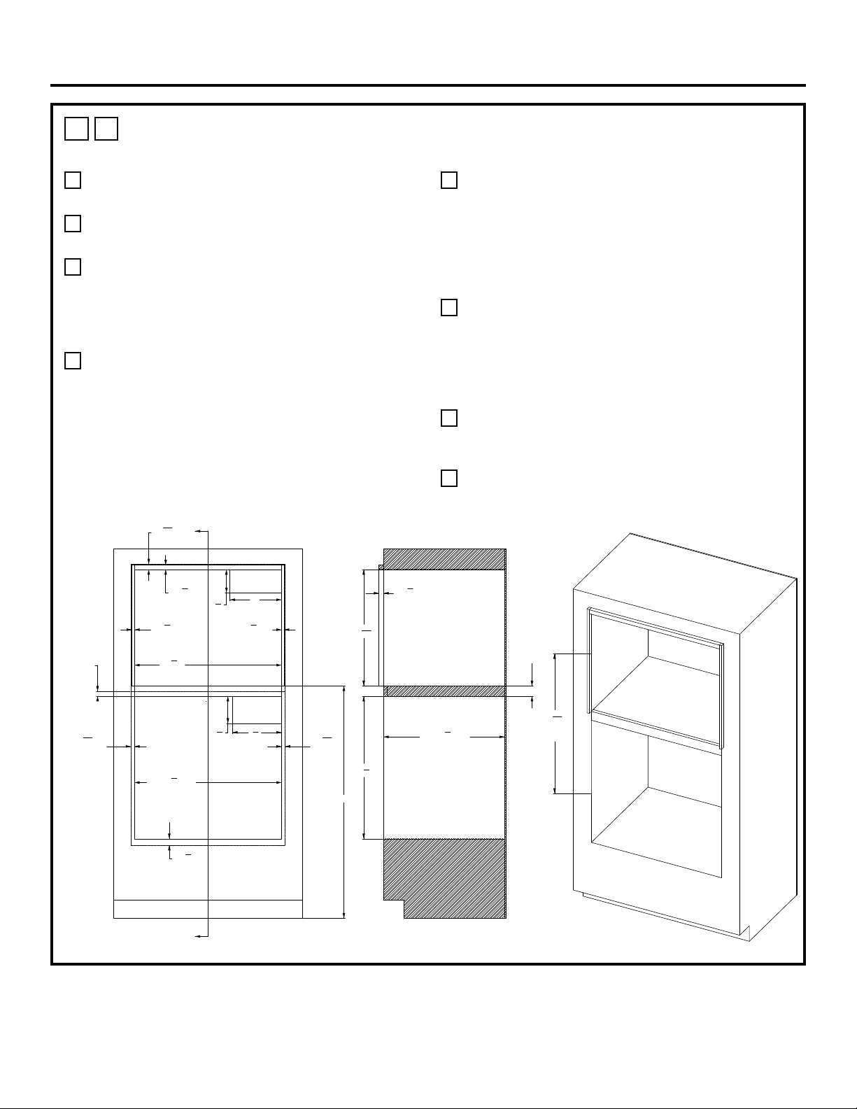
14 31-2001053 Rev. 0
Installations
1
H
HEARTH OVEN OVER FRENCH DOOR WALL OVEN –STANDARD
INSTALLATION WITH A 2” PLATFORM BETWEEN
A
45” is the required minimum installation height. Oven
may be installed higher based on owner preference.
B
Hearth Oven Platform must be able to support
200 lbs. (91kg).
C
Solid enclosure required on the top, bottom, left
side, right side and back. The back surface may
be drywall. Advanced fabrication and assembly
techniques are strongly encouraged to ensure
precise cabinet squareness and parallelism.
D
Junction box location: Must be flush with back
surface so as not to extend into the 23 ½ inch
cabinet depth. Junction box may also be located in
an adjacent cabinet.
E
A minimum 1/8” reveal BEYOND the OVERLAP
dimensions is recommended for proper drawer and
door operating clearance. For the Lower FRENCH
DOOR WALL OVEN, please carefully refer to the
door opening restrictions associated with nearby
countertops, walls and cabinet fronts to adjust the
overlap value accordingly.
F
Exterior cleats may be added to the sides and top
of the Hearth Oven opening in order to bring the
front surface of the Hearth Oven into alignment with
the front surface of the wall oven below. Finish per
customer requirements. A flat black finish may better
match the side appearance of the oven below.
G
For the FRENCH DOOR WALL OVEN, the
stainless-steel LOWER TRIM supplied with the unit
is the only option.
H
The opening center line dimension is taken at the
FRONT OPENING of each enclosure.
ELEC.
SEE NOTE D
ELEC.
SEE NOTE D
HEARTH OVEN PLATFORM
SEE NOTE B
4
1
2
"
10"
5
1
4
" 9
1
2
"
1
1
16
"
OVERLAP
11
16
"
OVERLAP
SEE NOTE E
1
1
4
"
OVERLAP
11
16
"
OVERLAP
SEE NOTE E
1"
OVERLAP
A
A
SECTION A-A
27
3
32
"
C
L
TO
C
L
SEE NOTE H
7
8
"
SEE NOTE F
28
1
2
"
CUTOUT WIDTH
1
2
"
SEE NOTE F
1
2
"
SEE NOTE F
28
1
2
"
CUTOUT WIDTH
45" MIN
23
1
2
"
CABINET DEPTH
27
5
8
"
22
9
16
"
7
8
"
SEE NOTE F
2"
BETWEEN
CUTOUTS
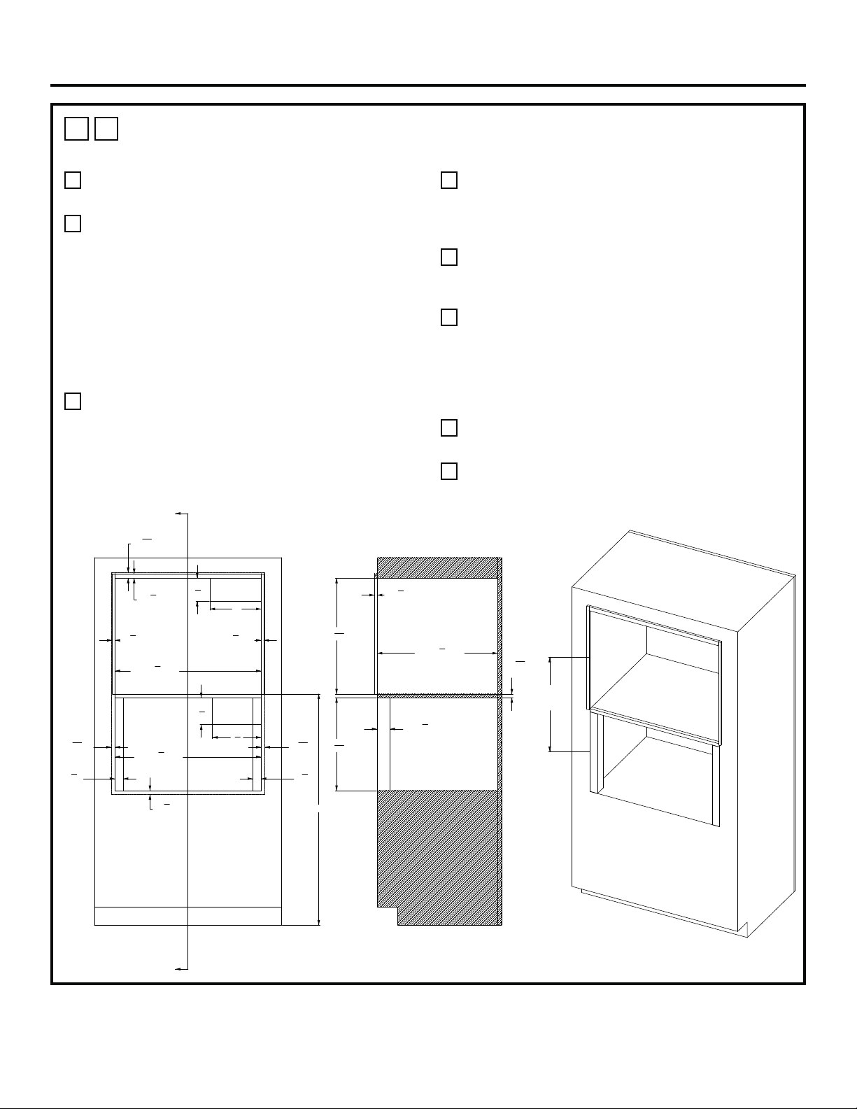
31-2001053 Rev. 0 15
Installations
1
I
HEARTH OVEN OVER STEAM OVEN –STANDARD INSTALLATION WITH A
MINIMUM GAP BETWEEN
A
45” is the required minimum installation height. Oven
may be installed higher based on owner preference.
B
Hearth Oven Platform must be able to support
200 lbs. (91kg). For this installation, it is highly
recommended to lock the platform into the side
walls using wood joinery such as a Dado Joint.
Fasteners and wood glue are also encouraged to
further reinforce the locking wood joinery. The wood
grain of the platform shall be oriented left to right.
The front nose of the platform shall be a finished
appearance surface. See illustrations 1Q & 1R for
joinery concepts.
C
Solid enclosure required on the top, bottom, left
side, right side and back. The back surface may
be drywall. Advanced fabrication and assembly
techniques are strongly encouraged to ensure
precise cabinet squareness and parallelism.
D
Junction box location: Must be flush with back
surface so as not to extend into the 23 ½ inch
cabinet depth. Junction box may also be located in
an adjacent cabinet.
E
A minimum 1/8” reveal BEYOND the OVERLAP
dimensions is recommended for proper drawer and
door operating clearance.
F
Exterior cleats may be added to the sides and top
of the Hearth Oven opening in order to bring the
front surface of the Hearth Oven into alignment with
the front surface of the wall oven below. Finish per
customer requirements. A flat black finish may better
match the side appearance of the oven below.
G
A LOWER VENT TRIM option is NOT available for
this cabinet configuration.
H
The opening center line dimension is taken at the
FRONT OPENING of each enclosure.
ELEC
SEE NOTE D
HEARTH OVEN PLATFORM
SEE NOTE B
ELEC
4
1
2
"
10"
1
1
16
"
OVERLAP
3
4
"
OVERLAP
11
16
"
OVERLAP
11
16
"
OVERLAP
9
1
2
"
5
1
4
"
A
A
21 3/64" MIN
C
L
TO
C
L
SEE NOTE H
SECTION A-A
7
8
"
SEE NOTE F
1
2
"
SEE NOTE F
1
2
"
SEE NOTE F
28
1
2
"
CUTOUT WIDTH
1
5
8
"
CLEAT
1
5
8
"
CLEAT
45" MIN
28
1
2
"
CUTOUT WIDTH
1
2
"
SEE NOTE F
22
9
16
"
23
1
2
"
CABINET DEPTH
18
3
32
"
2
1
2
"
CLEAT DEPTH
23
32
"MIN
3/4" PLYWOOD
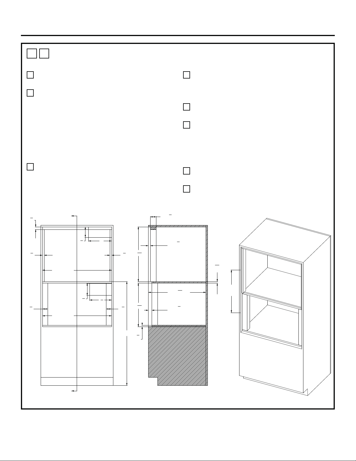
16 31-2001053 Rev. 0
Installations
1
J
HEARTH OVEN OVER STEAM OVEN – FLUSH-INSET INSTALLATION WITH A
MINIMUM GAP BETWEEN
A
45” is the required minimum installation height. Oven
may be installed higher based on owner preference.
B
Hearth Oven Platform must be able to support
200 lbs. (91kg). For this installation, it is highly
recommended to lock the platform into the side
walls using wood joinery such as a Dado Joint.
Fasteners and wood glue are also encouraged to
further reinforce the locking wood joinery. The wood
grain of the platform shall be oriented left to right.
The front nose of the platform shall be a finished
appearance surface. See illustrations 1Q & 1R for
joinery concepts.
C
Solid enclosure required on the top, bottom, left
side, right side and back. The back surface may
be drywall. Advanced fabrication and assembly
techniques are strongly encouraged to ensure
precise cabinet squareness and parallelism.
D
Junction box location: Must be flush with back
surface so as not to extend into the 24-15/16”
cabinet depth. Junction box may also be located in
an adjacent cabinet.
E
The front surface of the interior cleats shall be a
finished appearance surface.
F
An optional LOWER TRIM KIT may be installed with
a CUT OUT OPENING & BOTTOM CLEAT height
changes. Trim kit ZXSTEAM1 can be used with
a CUT OUT OPENING height of 19-25/32” and a
BOTTOM CLEAT height of 1-5/8”.
Please call 1-800-626-2000 with any questions.
G
The opening center line dimension is taken at the
FRONT OPENING of each enclosure.
H
Steam Oven bottom surface cleat is to be 5/8” thick
MDF fiber board or equivalent.
ELEC.
SEE NOTE D
ELEC.
HEARTH OVEN PLATFORM
SEE NOTE B
STEAM OVEN PLATFORM
SEE NOTE H
10"
4
1
2
"
9
1
2
"
5
1
4
"
A
A
SECTION A-A
1
1
8
"
CLEAT
3
4
"
CLEAT
3
4
"
CLEAT
2
3
8
"
CLEAT
2
3
8
"
CLEAT
30"
CUTOUT WIDTH
30"
CUTOUT WIDTH
45"
MIN
21 61/64" MIN
C
L
TO
C
L
SEE NOTE G
2
1
2
"
CLEAT DEPTH
7
8
"
HEARTH OVEN
CLEAT SETBACK
23
11
16
"
5
8
"
MDF
SEE NOTE H
18
25
32
"
24
15
16
"
CABINET DEPTH
1
1
2
"
STEAM OVEN
CLEAT SETBACK
23
32
" MIN
"3/4 PLYWOOD"
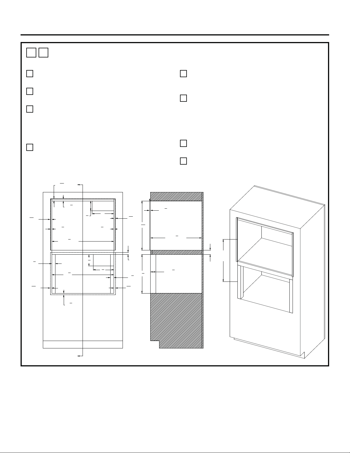
31-2001053 Rev. 0 17
Installations
1
K
HEARTH OVEN OVER STEAM OVEN –STANDARD INSTALLATION WITH A
2” PLATFORM BETWEEN
A
45” is the required minimum installation height. Oven
may be installed higher based on owner preference.
B
Hearth Oven Platform must be able to support
200 lbs. (91kg).
C
Solid enclosure required on the top, bottom, left
side, right side and back. The back surface may
be drywall. Advanced fabrication and assembly
techniques are strongly encouraged to ensure
precise cabinet squareness and parallelism.
D
Junction box location: Must be flush with back
surface so as not to extend into the 23 ½ inch
cabinet depth. Junction box may also be located in
an adjacent cabinet.
E
A minimum 1/8” reveal BEYOND the OVERLAP
dimensions is recommended for proper drawer and
door operating clearance.
F
Exterior cleats may be added to the sides and top
of the Hearth Oven opening in order to bring the
front surface of the Hearth Oven into alignment with
the front surface of the wall oven below. Finish per
customer requirements. A flat black finish may better
match the side appearance of the oven below.
G
A LOWER VENT TRIM option is NOT available for
this cabinet configuration.
H
The opening center line dimension is taken at the
FRONT OPENING of each enclosure.
ELEC.
SEE NOTE D
ELEC.
SEE NOTE D
HEARTH OVEN PLATFORM
SEE NOTE B
4
1
2
"
10"
5
1
4
"
9
1
2
"
3
4
"
OVERLAP
1"
OVERLAP
11
16
"
OVERLAP
11
16
"
OVERLAP
1
1
16
"
OVERLAP
7
8
"
SEE NOTE F
1
2
"
SEE NOTE F
1
2
"
SEE NOTE F
28
1
2
"
CUTOUT WIDTH
28
1
2
"
CUTOUT WIDTH
1
5
8
"
CLEAT
1
5
8
"
CLEAT
1
2
"
SEE NOTE F
22
9
16
"
17
3
4
"
2"
BETWEEN
CUTOUTS
23
1
2
"
CABINET DEPTH
2
1
2
"
CLEAT DEPTH
SECTION A-A
22 5/32"
C
L
TO
C
L
SEE NOTE H
11
16
"
OVERLAP
11
16
"
OVERLAP
A
A
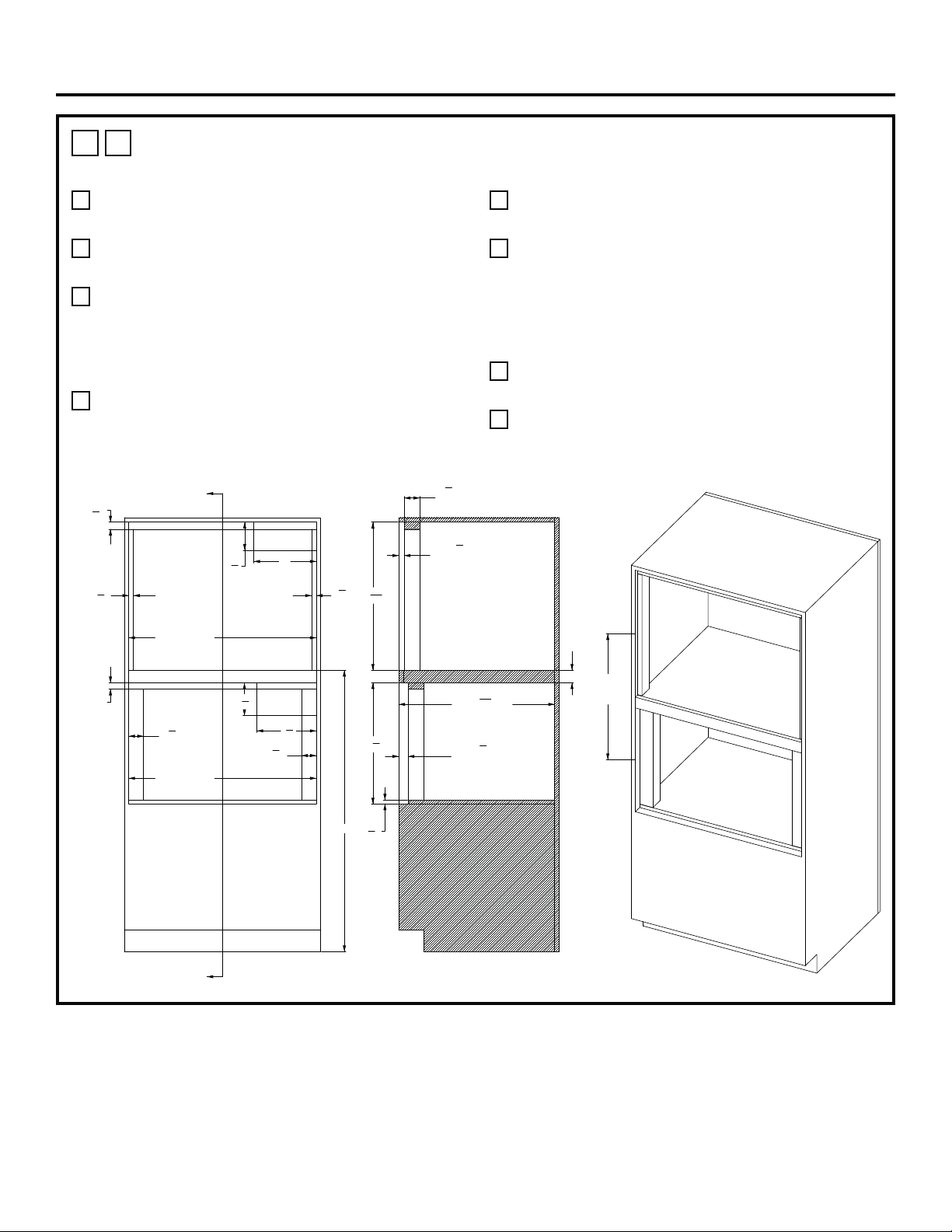
18 31-2001053 Rev. 0
Installations
1
L
HEARTH OVEN OVER STEAM OVEN – FLUSH-INSET INSTALLATION WITH A
2” PLATFORM BETWEEN
A
45” is the required minimum installation height. Oven
may be installed higher based on owner preference.
B
Hearth Oven Platform must be able to support
200 lbs. (91kg).
C
Solid enclosure required on the top, bottom, left
side, right side and back. The back surface may
be drywall. Advanced fabrication and assembly
techniques are strongly encouraged to ensure
precise cabinet squareness and parallelism.
D
Junction box location: Must be flush with back
surface so as not to extend into the 24-15/16”
cabinet depth. Junction box may also be located in
an adjacent cabinet.
E
The front surface of the interior cleats shall be a
finished appearance surface.
F
An optional LOWER TRIM KIT may be installed
with a CUT OUT OPENING & BOTTOM CLEAT
height changes. Trim kit ZXSTEAM1 can be used
with a CUT OUT OPENING height of 20-3/8” and a
BOTTOM CLEAT height of 1-5/8”.
Please call 1-800-626-2000 with any questions.
G
The opening center line dimension is taken at the
FRONT OPENING of each enclosure.
H
Steam Oven bottom surface cleat is to be 5/8” thick
MDF fiber board or equivalent.
ELEC.
SEE NOTE D
ELEC.
HEARTH OVEN PLATFORM
SEE NOTE B
STEAM OVEN PLATFORM
SEE NOTE H
4
1
2
"
10"
5
1
4
"
9
1
2
"
45" MIN
30"
CUTOUT WIDTH
30"
CUTOUT WIDTH
1
1
8
"
CLEAT
3
4
"
CLEAT
3
4
"
CLEAT
2
3
8
"
CLEAT
2
3
8
"
CLEAT
1"
CLEAT
23 17/32"
C
L
TO
C
L
SEE NOTE G
7
8
"
HEARTH OVEN
CLEAT SETBACK
1
1
2
"
STEAM OVEN
CLEAT SETBACK
24
15
16
"
CABINET DEPTH
2"
BETWEEN
CUTOUTS
5
8
"
MDF
SEE NOTE H
19
3
8
"
23
11
16
"
2
1
2
"
CLEAT
DEPTH
SECTION A-A
A
A
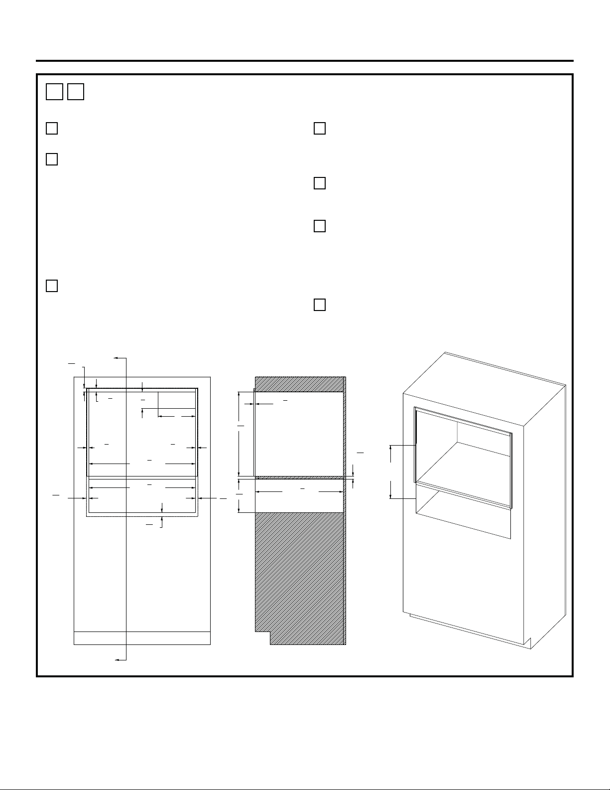
31-2001053 Rev. 0 19
Installations
1
M
HEARTH OVEN OVER WARMING DRAWER –STANDARD INSTALLATION
WITH A MINIMUM GAP BETWEEN
A
45” is the required minimum installation height. Oven
may be installed higher based on owner preference.
B
Hearth Oven Platform must be able to support
200 lbs. (91kg). For this installation, it is highly
recommended to lock the platform into the side
walls using wood joinery such as a Dado Joint.
Fasteners and wood glue are also encouraged to
further reinforce the locking wood joinery. The wood
grain of the platform shall be oriented left to right.
The front nose of the platform shall be a finished
appearance surface. See illustrations 1Q & 1R for
joinery concepts.
C
Solid enclosure required on the top, bottom, left
side, right side and back. The back surface may
be drywall. Advanced fabrication and assembly
techniques are strongly encouraged to ensure
precise cabinet squareness and parallelism.
D
Junction box location: Must be flush with back
surface so as not to extend into the 23 ½ inch
cabinet depth. Junction box may also be located in
an adjacent cabinet.
E
A minimum 1/8” reveal BEYOND the OVERLAP
dimensions is recommended for proper drawer and
door operating clearance.
F
Exterior cleats may be added to the sides and top
of the Hearth Oven opening in order to bring the
front surface of the Hearth Oven into alignment with
the front surface of the wall oven below. Finish per
customer requirements. A flat black finish may better
match the side appearance of the oven below.
G
The opening center line dimension is taken at the
FRONT OPENING of each enclosure.
ELEC
SEE NOTE D
HEARTH OVEN PLATFORM
SEE NOTE B
1
1
16
"
OVERLAP
1
1
16
"
OVERLAP
11
16
"
OVERLAP
11
16
"
OVERLAP
4
1
2
"
10"
7
8
"
SEE NOTE F
1
2
"
SEE NOTE F
1
2
"
SEE NOTE F
28
1
2
"
CUTOUT WIDTH
28
1
2
"
CUTOUT WIDTH
16 31/64"
C
L
TO
C
L
SEE NOTE G
3
8
"
SEE NOTE F
22
9
16
"
8
31
32
"
23
1
2
"
CABINET DEPTH
23
32
"MIN
"3/4 PLYWOOD"
SECTION A-A
A
A
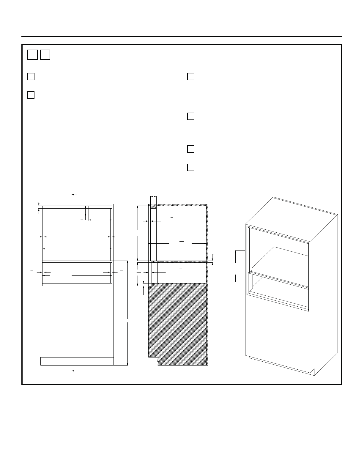
20 31-2001053 Rev. 0
Installations
1
N
HEARTH OVEN OVER WARMING DRAWER – FLUSH-INSET INSTALLATION
WITH A MINIMUM GAP BETWEEN
A
45” is the required minimum installation height. Oven
may be installed higher based on owner preference.
B
Hearth Oven Platform must be able to support
200 lbs. (91kg). For this installation, it is highly
recommended to lock the platform into the side
walls using wood joinery such as a Dado Joint.
Fasteners and wood glue are also encouraged to
further reinforce the locking wood joinery. The wood
grain of the platform shall be oriented left to right.
The front nose of the platform shall be a finished
appearance surface. See illustrations 1Q & 1R for
joinery concepts.
C
Solid enclosure required on the top, bottom, left
side, right side and back. The back surface may
be drywall. Advanced fabrication and assembly
techniques are strongly encouraged to ensure
precise cabinet squareness and parallelism.
D
Junction box location: Must be flush with back
surface so as not to extend into the 24-15/16”
cabinet depth. Junction box may also be located in
an adjacent cabinet.
E
The front surface of the interior cleats shall be a
finished appearance surface.
F
The opening center line dimension is taken at the
FRONT OPENING of each enclosure.
ELEC.
SEE NOTE D
HEARTH OVEN PLATFORM
SEE NOTE B
10"
4
1
2
"
1
1
8
"
CLEAT
3
4
"
CLEAT
3
4
"
CLEAT
45" MIN
30"
CUTOUT WIDTH
30"
CUTOUT WIDTH
3
4
"
CLEAT
3
4
"
CLEAT
17 39/64" MIN
C
L
TO
C
L
SEE NOTE F
2
1
2
"
CLEAT
DEPTH
7
8
"
HEARTH OVEN
CLEAT SETBACK
23
11
16
"
1
1
8
"
CLEAT
10
3
32
"
1
3
8
"
WARMING DRAWER
CLEAT SETBACK
24
15
16
"
CABINET DEPTH
23
32
"MIN
"3/4 PLYWOOD"
SECTION A-A
A
A
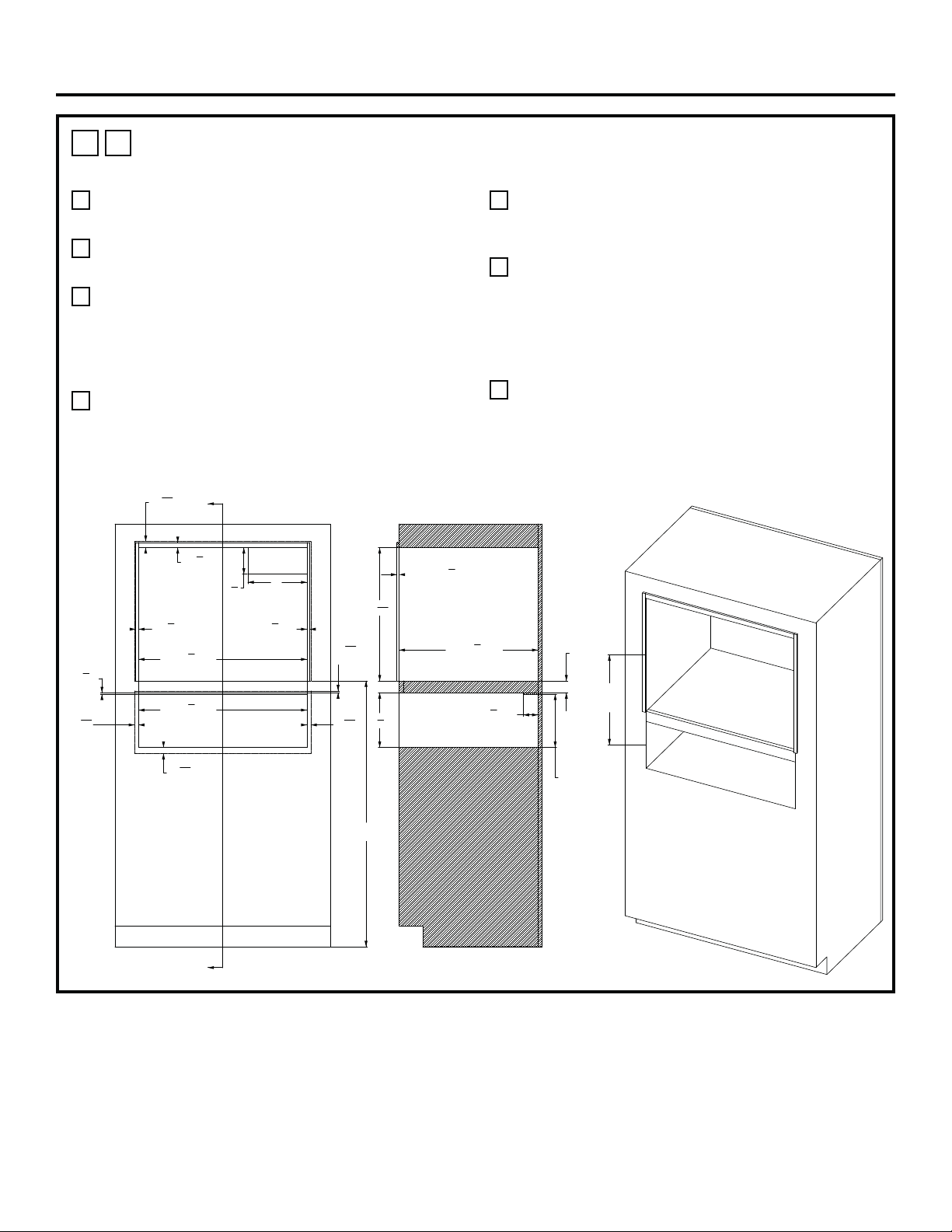
31-2001053 Rev. 0 21
Installations
1
O
HEARTH OVEN OVER WARMING DRAWER –STANDARD INSTALLATION
WITH A 2” PLATFORM BETWEEN
A
45” is the required minimum installation height. Oven
may be installed higher based on owner preference.
B
Hearth Oven Platform must be able to support
200 lbs. (91kg).
C
Solid enclosure required on the top, bottom, left
side, right side and back. The back surface may
be drywall. Advanced fabrication and assembly
techniques are strongly encouraged to ensure
precise cabinet squareness and parallelism.
D
Junction box location: Must be flush with back
surface so as not to extend into the 23 ½ inch
cabinet depth. Junction box may also be located in
an adjacent cabinet.
E
A minimum 1/8” reveal BEYOND the OVERLAP
dimensions is recommended for proper drawer and
door operating clearance.
F
Exterior cleats may be added to the sides and top
of the Hearth Oven opening in order to bring the
front surface of the Hearth Oven into alignment with
the front surface of the wall oven below. Finish per
customer requirements. A flat black finish may better
match the side appearance of the oven below.
G
The opening center line dimension is taken at the
FRONT OPENING of each enclosure.
ELEC.
SEE NOTE D
HEARTH OVEN PLATFORM
SEE NOTE B
4
1
2
"
10"
5
16
"
OVERLAP
1
1
16
"
OVERLAP
11
16
"
OVERLAP
11
16
"
OVERLAP
1
1
16
"
OVERLAP
7
8
"
SEE NOTE F
1
2
"
SEE NOTE F
1
2
"
SEE NOTE F
28
1
2
"
CUTOUT WIDTH
28
1
2
"
CUTOUT WIDTH
1
4
"
CLEAT
2"
BETWEEN
CUTOUTS
2
1
2
"
CLEAT DEPTH
23
1
2
"
CABINET DEPTH
3
8
"
SEE NOTE F
22
9
16
"
9
1
4
"
SECTION A-A
17 29/32"
C
L
TO
C
L
SEE NOTE G
45"
MIN
A
A
9"
PLATFORM
TO ANTI TIP CLEAT
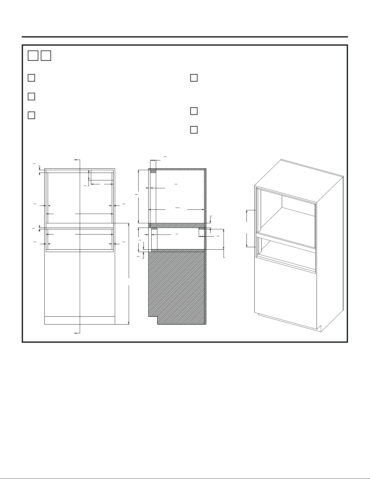
22 31-2001053 Rev. 0
Installations
1
P
HEARTH OVEN OVER WARMING DRAWER – FLUSH-INSET INSTALLATION
WITH A 2” PLATFORM BETWEEN
A
45” is the required minimum installation height. Oven
may be installed higher based on owner preference.
B
Hearth Oven Platform must be able to support
200 lbs. (91kg).
C
Solid enclosure required on the top, bottom, left
side, right side and back. The back surface may
be drywall. Advanced fabrication and assembly
techniques are strongly encouraged to ensure
precise cabinet squareness and parallelism.
D
Junction box location: Must be flush with back
surface so as not to extend into the 24-15/16”
cabinet depth. Junction box may also be located in
an adjacent cabinet.
E
The front surface of the interior cleats shall be a
finished appearance surface.
F
The opening center line dimension is taken at the
FRONT OPENING of each enclosure.
ELEC.
SEE NOTE D
HEARTH OVEN PLATFORM
SEE NOTE B
4
1
2
"
10"
1
1
8
"
CLEAT
30"
CUTOUT WIDTH
3
4
"
CLEAT
3
4
"
CLEAT
5
8
"
CLEAT
3
4
"
CLEAT
3
4
"
CLEAT
30"
CUTOUT WIDTH
45"
MIN
19 7/32"
C
L
TO
C
L
SEE NOTE F
7
8
"
HEARTH OVEN
CLEAT SETBACK
24
15
16
"
CABINET DEPTH
1
3
8
"
WARMING DRAWER
CLEAT SETBACK
2
1
2
"
CLEAT
DEPTH
23
11
16
"
2
1
2
"
CLEAT
DEPTH
10
3
4
"
1
1
8
"
CLEAT
2"
BETWEEN
CUTOUTS
SECTION A-A
A
A
9"
PLATFORM TO
ANTI TIP CLEAT
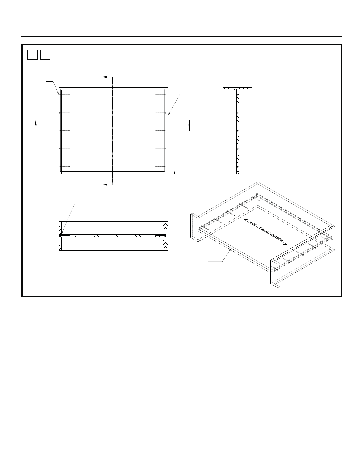
31-2001053 Rev. 0 23
Installations
1
Q
HEARTH OVEN PLATFORM FOR MINIMUM GAP BETWEEN APPLIANCES:
DADO & MECHANICAL FASTENER CONCEPT
Cosmetic
Nose
Cosmetic Panel
To Cover Joinery
For Exposed Wall
Mechanical
Fasteners
AA
B
B
SECTION A-A
DADO Joints
&
Wood Glue
SECTION B-B
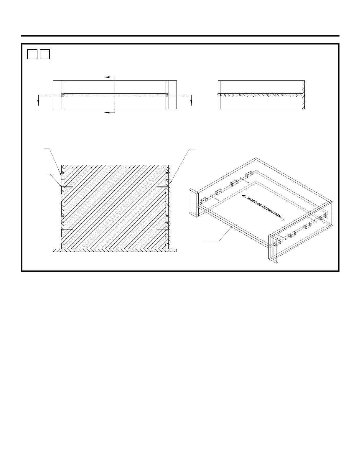
24 31-2001053 Rev. 0
Installations
1
R
HEARTH OVEN PLATFORM FOR MINIMUM GAP BETWEEN APPLIANCES:
TENON & MECHANICAL FASTENER CONCEPT
Cosmetic
Nose
AA
B
B
SECTION A-A
Cosmetic Panel
To Cover Joinery
For Exposed Wall
Tenon
Joints
Mechanical
Fasteners
SECTION B-B
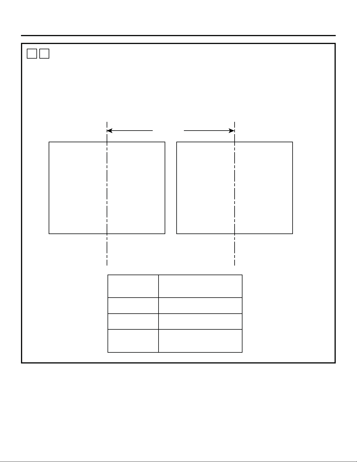
31-2001053 Rev. 0 25
1
S
SIDE-BY-SIDE COMBO INSTALLATION
For a list of products compatible with Hearth Oven Side-by-Side Installation check online at
geappliances.com/combinations.
Please refer to the installation literature of both units for such installations.
For assistance with cabinet design please connect with a Monogram Designer.
Installations
Dimension A
Hearth Oven
Refer to 1A or
1B for Cutout
Dimensions
Refer to the
Specific Product’s
Installation
Instructions for
Cutout Dimensions
Oven Type
Min. Distance - Dimension A
Product to Product
Centerlines
Hearth Oven next
to Wall Oven
30.5”
Hearth Oven next
to Steam Oven
30.5”
Hearth Oven next
to French Door
Wall Oven
42.5”
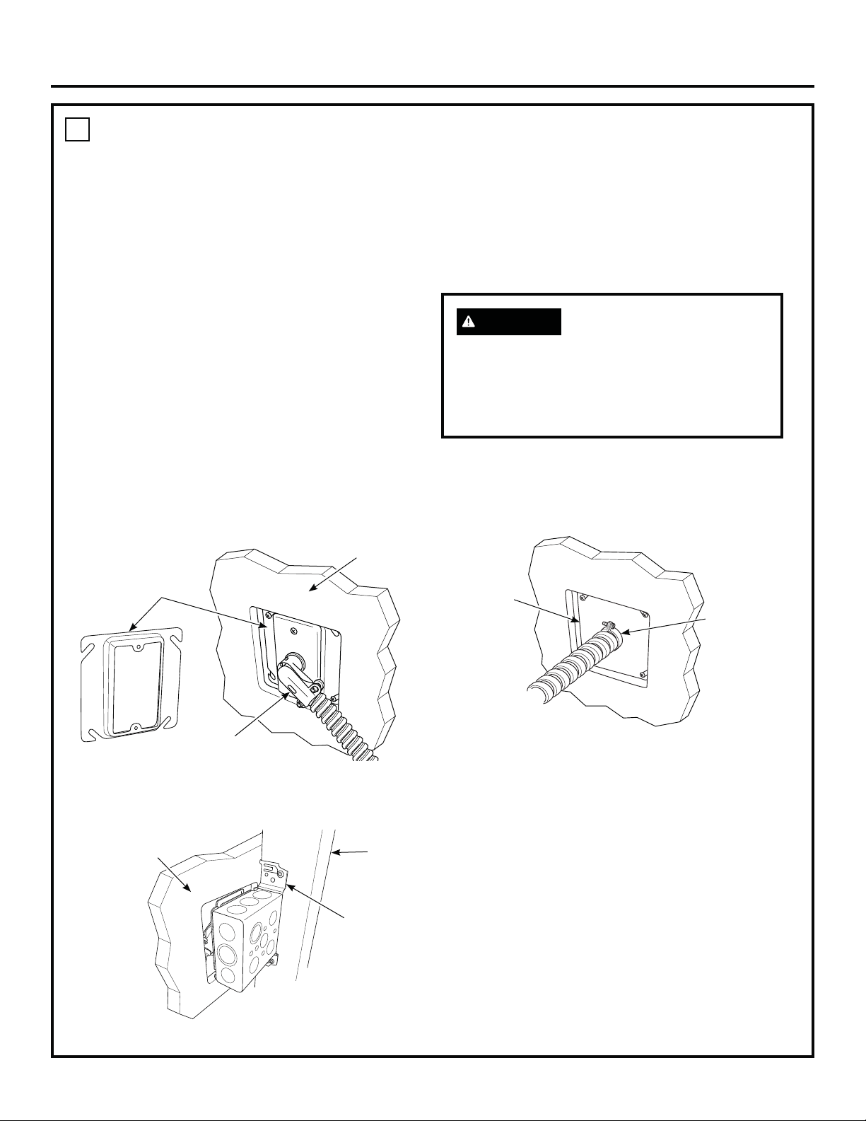
26 31-2001053 Rev. 0
Installation
2
ELECTRICAL CONNECTIONS
ATTENTION INSTALLER
All electric wall ovens must be hard wired (direct
wired) into an approved junction box. A plug and
receptacle is NOT permitted on these products.
Do not shorten the flexible conduit. The conduit
strain relief clamp must be securely attached to
the junction box and the flexible conduit must
be securely attached to the clamp. If the flexible
conduit will not fit within the clamp, do not
install the oven until a clamp of the proper size is
obtained.
NOTE TO ELECTRICIAN: The 3 power leads supplied
with this appliance are UL recognized for connection
to heavier gauge household wiring. The insulation of
these 3 leads is rated at temperatures much higher
than the temperature rating of household wiring.
The current carrying capacity of the conductor is
governed by the wire gauge and the temperature
rating of the insulation around the wire.
WARNING
Improper connection of
aluminum house wiring to copper leads can
result in an electrical hazard or fire. Use only
connectors designed for joining copper to
aluminum and follow the manufacturer’s
recommended procedure closely.
RECOMMENDED INSTALLATION OPTIONS
Option 1 - A junction box with a plaster ring and 90°
strain relief, mounted to a stud behind
the drywall.
Option 2 - Standard junction box with a straight strain
relief, mounted to a stud behind the drywall.
Plaster Ring
Front of Drywall
FRONT VIEW
90° Strain Relief
Stud
BACK VIEW
Back of Drywall
Mounted
Junction Box
Straight Strain
Relief
Junction
Box
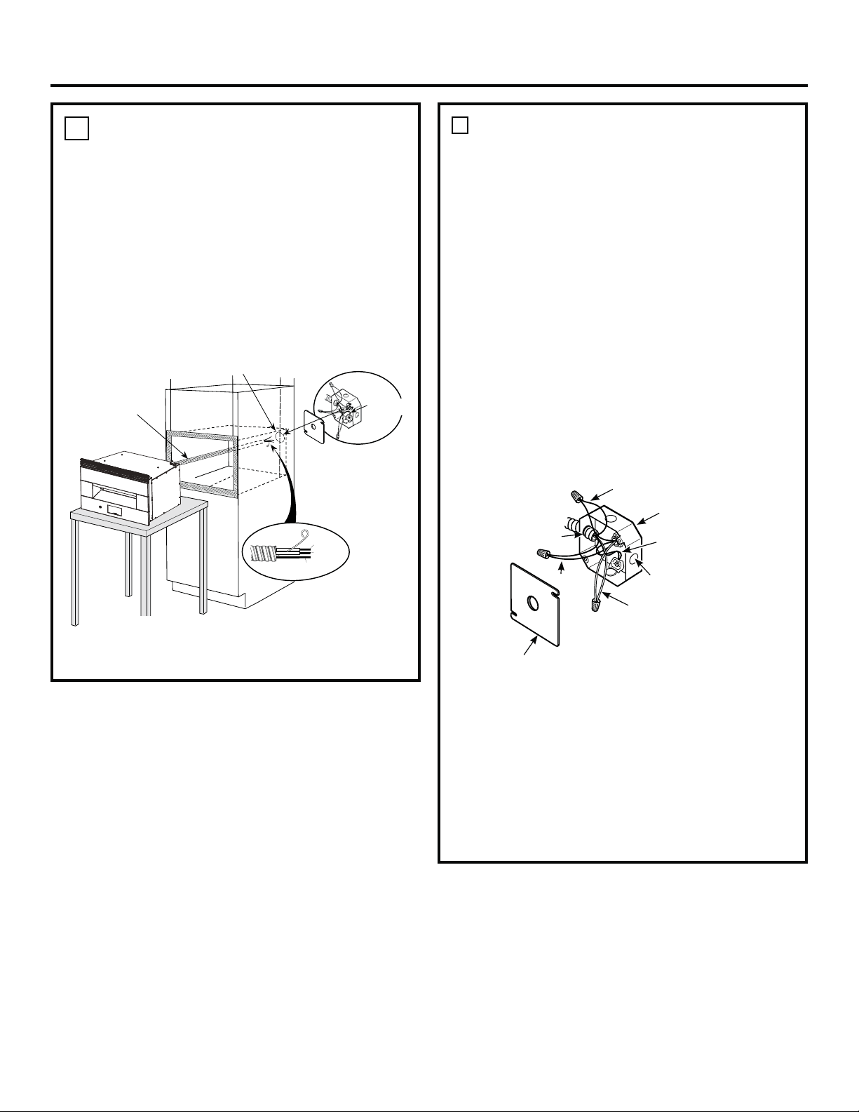
31-2001053 Rev. 0 27
Installation
A
NEW CONSTRUCTION AND FOUR-
CONDUCTOR BRANCH CIRCUIT CONNECTION
• When installing in new construction, or
• When installing in a mobile home, or
• When installing in a recreational vehicle, or
• When local codes do not permit grounding through
neutral:
NOTE: If residence leads or ground are aluminum
conductors, see WARNING on page 5.
When connecting to a four-conductor branch circuit, if
local codes permit:
1. Free the neutral (white) lead from being restrained
to any other wires. If necessary, cut the neutral
(white) lead and then re-strip it to expose the proper
length of conductor.
2. Attach the appliance grounding lead (green or bare
copper) in accordance with local codes.
3. Connect the oven neutral (white) lead to the branch
circuit neutral (white or gray) in accordance with
local codes, using a wire nut.
4. Connect the oven red lead to the branch circuit red
lead and the oven black lead to the branch circuit
black lead in accordance with local codes, using
wire nuts.
5. Install proper strain relief clamp.
6. Install junction box cover.
Junction Box Cover
White
Black
Red
Branch
circuit
Ground
wires
Alternate
knockout
Range
conduit
snaps
into box
2
ELECTRICAL CONNECTIONS (Cont)
1. Turn off the circuit breaker or remove fuses to the
oven branch circuit.
2. With the oven supported on a table or platform in
front of the cabinet opening, connect the flexible
conduit to the electrical junction box as shown
below. Position the conduit in such a manner that
it will lie in a natural loop, in the conduit pocket
behind the unit, when the oven is installed. You will
need to purchase an appropriate strain relief clamp
to complete the connection of the conduit to the
junction box.
Strain Relief Clamp
(not included) must be
used at Junction Box.Place oven on a support
to assist in connecting
conduit, must support
200lbs (91kg).
Junction Box Location
Conduit
GROUND
WIRE
GROUND
RED
WHITE
BLACK
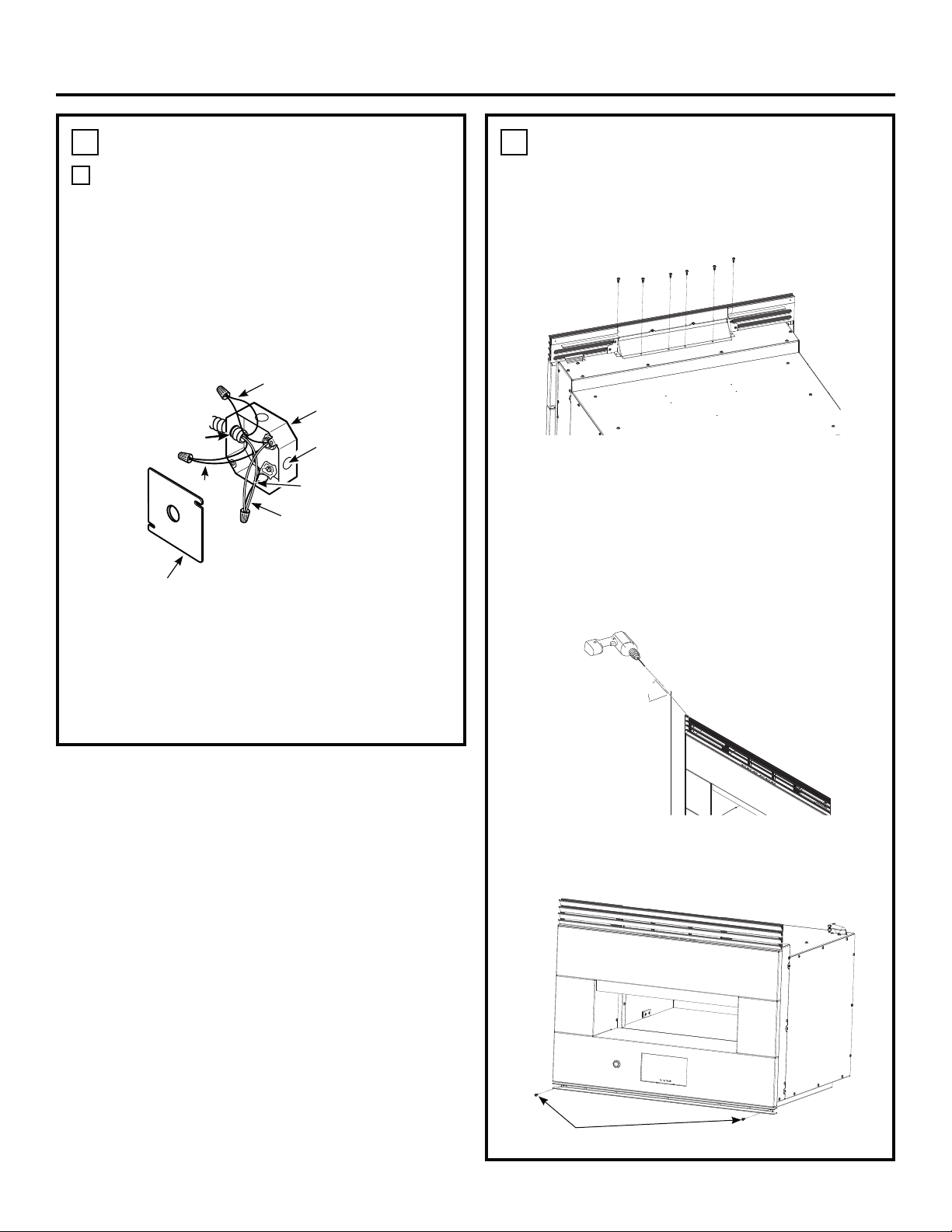
28 31-2001053 Rev. 0
Installation
2
ELECTRICAL CONNECTIONS (Cont)
B
THREE-CONDUCTOR BRANCH CIRCUIT
CONNECTION
NOTE: If residence leads are aluminum conductors,
see WARNING on page 5.
When connecting to a three-conductor branch circuit,
if local codes permit:
1. Connect the oven ground conductor along with the
neutral (white) lead to the branch circuit neutral
(white or gray in color), using a wire nut.
2. Connect the oven red lead to the branch circuit red
lead and the oven black lead to the branch circuit
black lead in accordance with local codes, using
wire nuts.
3. Install proper strain relief clamp.
4. Install junction box cover.
Ground and
neutral wires (white)
Tape or Crimp
Neutral wire
connection
Black
Red
Branch
circuit
Alternate
knockout
Range
conduit
snaps
into box
Junction Box Cover
3
INSTALLING THE OVEN IN THE
CABINET
1. Before lifting oven into cabinet cutout, remove six
screws from top vent and attach top grille to top of
oven using the same screws as shown.
2. Lift oven into cabinet cutout using the bottom as a
grip. Do not lift by the oven opening.
3. Carefully slide the oven back into the cutout until
the top grille just touches the front face of the
cabinet. NOTE: Do not push too far or damage to
the top grille may occur.
4. Pre-drill top grille mounting holes into cabinet using
3/32” drill bit and the hole in the trim as a guide.
Install two 3/4” Philips screws.
5. After oven is installed in cabinet, align Lower Vent
Trim with holes on mounting brackets and install
using two 1/2” Torx screws.
45°
Screws
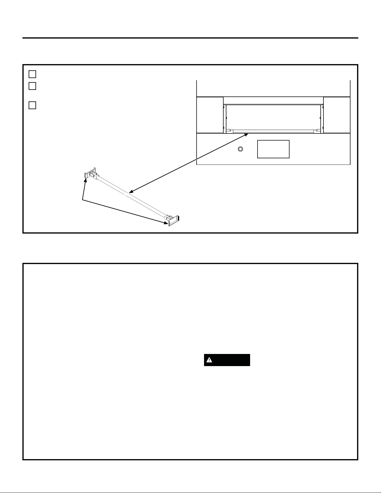
31-2001053 Rev. 0 29
Installation
PRE-TEST CHECKLIST
OPERATION CHECKLIST
Remove all protective film, if present.
Check to be sure that all wiring is secure and not
pinched.
Remove cooking deck shipping supports by:
1. Remove Shipping Support Dowel by pulling up
on one end.
2. Remove both Shipping Support Shoes, Slide out
from wall towards center of Stone.
3. Pull out from oven and discard.
IMPORTANT
• Remove all items from the inside of the oven.
• Check that conduit is securely connected to the
junction box.
• Turn on the power to the oven. (Refer to your Owner’s
Manual.) Verify that all cooking functions operate
properly.
• Check that the circuit breaker is not tripped nor the
house fuse blown.
• See your Owner’s Manual for troubleshooting list.
NOTE TO ELECTRICIAN: The power leads supplied
with this appliance are UL recognized for connections
to larger gauge household wiring. The insulation of
these leads is rated at temperatures much higher
than the temperature rating of household wiring. The
current carrying capacity of a conductor is governed
by the wire gauge and also the temperature rating of
the insulation around the wire.
NOTE: ALUMINUM WIRING
A.
WARNING
IMPROPER CONNECTION OF
ALUMINUM HOUSE WIRING TO THE COPPER
LEADS CAN RESULT IN AN ELECTRICAL
HAZARD OR FIRE.
B. Splice copper wires to aluminum wiring using
special connectors designed and UL approved
for joining copper to aluminum, and follow
the manufacturer’s recommended connector
procedure closely.
NOTE: Wire used, location and enclosure of
splices, etc., must conform to good wiring
practice and local codes.
Shipping
Support
Shoes

NOTE: While performing installations described in this book,
safety glasses or goggles should be worn.
NOTE: Product improvement is a continuing endeavor at
GE Appliances. Therefore, materials, appearance and
specifications are subject to change without notice.
Printed in the United States
31-2001053 Rev. 0
01-22 GEA

MONOGRAM.COM
INSTRUCCIONE
DE INSTALACIÓN
Horno de Hogar Para Interiores
ZEP30FR
ESPAÑOL.
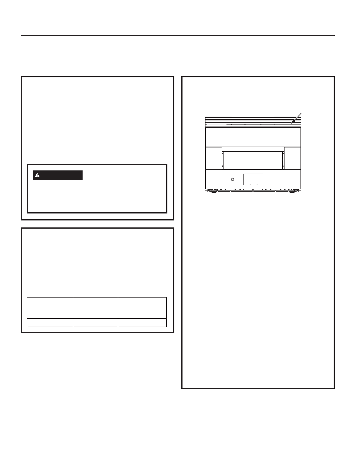
2 31-2001053 Rev. 0
Información de Seguridad
LEA Y GUARDE ESTAS INSTRUCCIONES
¿Desea realizar una consulta o necesita ayuda con su electrodoméstico? ¡Intente a través del sitio Web de Monogram las
24 horas del día, cualquier día del año! También puede comprar más grandiosos productos de Monogram y sacar ventaja
de todos nuestros servicios de soporte a través de Internet, diseñados para su conveniencia. En EE.UU.: monogram.com
o llame a Monogram al 800.444.1845.
PARA SU SEGURIDAD
• Cerciórese de que su horno sea instalado adecuadamente
por un instalador calificado o por un técnico de servicio.
• Cerciórese de que su horno esté firmemente instalado en
un gabinete que esté firmemente adherido a la estructura
de la casa. Nunca permita que nadie se suba, se siente,
se pare o se cuelgue del horno.
• Cerciórese de que los gabinetes y los revestimientos de
la pared alrededor del horno puedan soportar
las temperaturas (hasta 200°F [93,3°C]) generadas
por el horno.
ADVERTENCIA
La energía eléctrica hacia
la línea de suministro del horno debe ser
desconectada mientras se hacen las conexiones.
No hacer esto podría resultar en lesiones graves e
incluso provocar la muerte.
REQUISITOS ELÉCTRICOS
La etiqueta de características técnicas está ubicada en la
parte superior derecha del panel frontal.
Recomendamos que el cableado y la conexión eléctrica
de su horno los realice un electricista calificado. Después
de la instalación, solicite al electricista que le indique cómo
desconectar la energía de la cocina.
Consulte con su compañía de servicios local para obtener
los códigos eléctricos que sean aplicables en su área.
No hacer el cableado de su horno de manera apropiada,
respetando los códigos vigentes, podría resultar en
condiciones peligrosas. Si no existen códigos locales, su
aparato debe usar un cableado y fusibles que cumplan con
los requisitos del Código Eléctrico Nacional, ANSI/NFPA No.
70–Última edición. Usted puede obtener una copia de este
código disponible en National Fire Protection Association
(Asociación Nacional de Protección contra Incendios).
A partir del 1ro. de enero de 1996, el Código Eléctrico
Nacional requiere que todas las construcciones nuevas, pero
no existentes, usen una conexión de 4 conductores hacia
cualquier horno eléctrico. Cuando instale un horno eléctrico en
una construcción nueva, casa móvil, vehículo de recreación
o un área donde los códigos locales prohíban la conexión a
tierra a través del conductor neutro, siga las instrucciones en la
Sección CONSTRUCCIONES NUEVAS Y CONEXIONES DE
CIRCUITOS RAMALES DE 4 CONDUCTORES.
Usted debe usar un sistema eléctrico de fase única de
120/208 VAC o 120/240 VAC de 60 hercios. Si hace una
conexión a alambres de aluminio, debe usar conectores
adecuadamente instalados que estén aprobados para ser
utilizados con cableados de aluminio.
REQUISITOS ELÉCTRICOS
Este aparato debe abastecerse con la frecuencia y el
voltaje adecuados, y conectarse a un circuito eléctrico
individual con conexión a tierra con protección de un fusible
o interruptor automático. Lea la etiqueta de características
técnicas en la parte inferior del panel frontal, a fin de
determinar las especificaciones del producto. El siguiente
cuadro muestra la protección mínima recomendada para el
circuito especializado.
Potencia KW 240V
Potencia KW 208V
Tamaño Requerido
del Circuito
(Especializado)
9,7 KW–12,0 KW 8,4 KW–10,4 KW 50 Amp
Ubicación de la placa
de potencia

31-2001053 Rev. 0 3
Contenidos
CONTENIDOS
Información de Seguridad ..............................................2
Información de diseño
Dimensiones Del Producto (Con Marco).......................4
Lista De Control Antes De La Instalación .....................5
Información de instalación
Parts Included ...............................................................6
Materials Needed (not provided) ...................................6
Tools Needed ................................................................6
Instalación
1A: Espacio Libre para el Horno de Hogar -
Instalación Estándar ...............................................7
1B: Horno de Hogar – Instalación
con Montaje al Ras.................................................8
1C: Horno de Hogar sobre Horno de Pared –
Instalación Estándar con un Espacio Libre
Mínimo Intermedio ..................................................9
1D: Horno de Hogar sobre Horno de Pared –
Instalación con Montaje al Ras con un Espacio
Libre Mínimo Intermedio .......................................10
1E: Horno de Hogar sobre Horno de Pared –
Instalación Estándar con una Plataforma
Intermedia de 2” ...................................................11
1F: Horno de Hogar sobre Horno de Pared –
Instalación con Montaje al Ras con una Plataforma
Intermedia de 2” ....................................................12
1G: Horno de Hogar sobre Horno de Pared con Puerta
Francesa - Instalación Estándar con un Espacio
Libre Mínimo Intermedio ......................................13
1H: Horno de Hogar sobre Horno de Pared con Puerta
Francesa - Instalación Estándar con una Plataforma
Intermedia de 2” ...................................................14
1I: Horno de Hogar sobre Horno de Vapor -
Instalación Estándar con un Espacio Libre
Mínimo Intermedio .................................................15
1J: Horno de Hogar sobre Horno de Vapor –
Instalación con Montaje al Ras con un Espacio
Libre Mínimo Intermedio .......................................16
1K: Horno de Hogar sobre Horno de Vapor –
Instalación Estándar con una Plataforma Intermedia
de 2” .....................................................................17
1L: Horno de Hogar sobre Horno de Vapor –
Instalación con Montaje al Ras con una Plataforma
Intermedia de 2” ....................................................18
1M: Horno de Hogar sobre Horno de Vapor –
Instalación Estándar con un Espacio Libre
Intermedio Mínimo ...............................................19
1N: Horno de Hogar sobre Cajón para Calentar –
Instalación con Montaje al Ras con un Espacio
Libre Intermedio Mínimo .......................................20
1O: Horno de Hogar sobre Cajón para Calentar –
Instalación Estándar con una Plataforma Intermedia
de 2” .....................................................................21
1P: Horno de Hogar sobre Cajón para Calentar –
Instalación con Montaje al Ras con una Plataforma
Intermedia de 2” ...................................................22
1Q: Plataforma de Horno de Hogar para un Espacio
Libre Mínimo entre Electrodomésticos: Concepto de
Dado y Sujetador Mecánico .................................23
1R: Plataforma de Horno de Hogar para un Espacio
Libre Mínimo entre Electrodomésticos: Concepto de
Espiga y Sujetador Mecánico ...............................24
1S: Instalación de Combo de Lado a Lado ................25
2. Conexiones Eléctricas .............................................26
3. Instalación del Horno en el Gabinete ......................28
LISTA DE CONTROL ANTES DE LA PRUEBA ........29
LISTA DE CONTROL PARA LA OPERACIÓN .........29
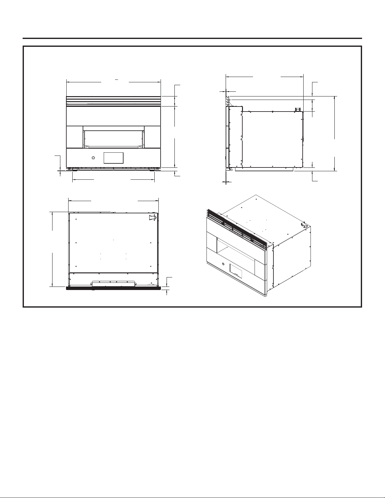
4 31-2001053 Rev. 0
Información de diseño
DIMENSIONES DEL PRODUCTO (CON MARCO)
29
3
4
"
Total en el Frente
Pie con Ajuste
del Marco de 1/8”
hasta el Marco
Inferior
Altura del Marco
Superior de 3 ¼”
Altura Frontal
de 19 5/16”
Pie de 1 1/32”
hasta la Parte
Inferior Frontal
Pies Exteriores
de 25 27/32” en Total
Total de Frente
de 21 ½” Hasta
el Espaciador Trasero
Ajuste del
Marco de 1/8”
Ajuste del
Marco de 1/8”
Pie de 23 9/16”
Hasta la Parte Inferior
de la Carcasa
Ajuste de 1 1/8”
hasta el Espaciador
Pie de 1 1/16”
Hasta la Parte
Inferior de la Carcasa
Parte Superior
de la Carcasa
de 3 21/32” hasta
el Espaciador
Ancho de la Carcasa
de 28 3/8” en los Laterales
de los Espaciadores
Ancho del Frente de 1”
Parte Trasera
del Marco Superior
de 23 ½” hasta
el Espaciador Trasero
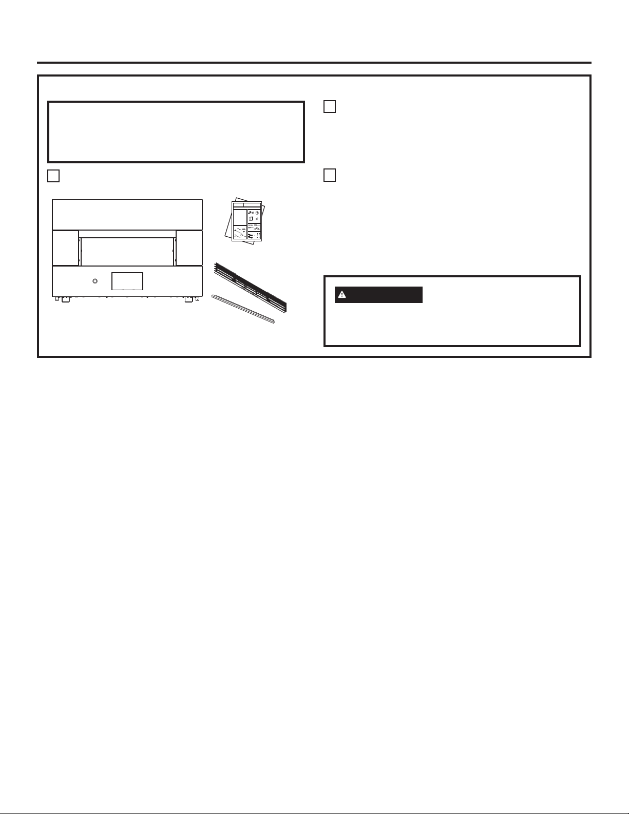
31-2001053 Rev. 0 5
Información de diseño
LISTA DE CONTROL ANTES DE LA INSTALACIÓN
¡TODA LA INFORMACIÓN DE INSTALACIÓN QUE
FIGURA EN LAS PÁGINAS SIGUIENTES DEBERÁ
SER USADA EN LA INSTALACIÓN DEL HORNO
ELÉCTRICO DE HOGAR PARA INTERIORES.
Retire los materiales de embalaje y extraiga el paquete de
instrucciones.
Extraiga las instrucciones de instalación del paquete y
léalas cuidadosamente antes de empezar la instalación.
Cerciórese de guardar bien todas las instrucciones,
Manual del propietario, Instalación, etc. para referencia en
el futuro.
Coloque el horno sobre la mesa o plataforma al nivel de
la abertura del gabinete. La plataforma debe soportar 200
lbs. (91 Kg).Estos hornos no están aprobados para las
instalaciones apilables.
El Horno de Hogar se podrá instalar en un gabinete solo,
sobre o junto a modelos aprobados. Para consultar sobre los
modelos aprobados, lea la etiqueta en la parte superior del
horno o visite geappliances.com/combinations.
PRECAUCIÓN
La instalación del horno por
debajo de la altura mínima de 45 pulgadas crea
riesgos de incendio para los niños. No instale el
mismo debajo de la altura mínima.
Paquete Informativo
Marco Incluido
Horno de Hogar
Be
f
ore yo
u be
gin
-
R
e
a
d
th
e
s
e
in
st
ru
c
t
io
ns
c
o
m
ple
te
l
y
a
n
d
ca
re
f
ully
.
IM
PO
RT
AN
T-
Sa
ve
th
e
s
e
i
n
s
t
ru
ct
io
n
s
f
o
r
l
o
ca
l
in
sp
e
c
t
or'
s
us
e
.
I
M
PO
RT
A
N
T-
OB
SE
RV
E
A
LL
G
O
VE
RN
I
N
G C
O
DE
S
AN
D
OR
DI
AN
C
E
S.
No
te
t
o
In
st
a
l
l
e
r
-
B
e
su
r
e
to
le
a
v
e
th
es
e
i
n
s
t
ru
ct
io
n
s
w
i
th
th
e
co
ns
u
me
r
.
O
W
NE
R-
Ke
e
p
th
e
s
e
inst
ru
c
t
io
ns
fo
r
futu
re refe
rence.
N
o
te
-
This
a
ppl
i
an
ce
mu
st
b
e
p
rop
er
ly
g
rou
nd
ed
(
i
f
a
pplic
a
b
le
).
Be
f
ore you
b
e
gin-
Re
ad
th
es
e
inst
ru
c
t
io
n
s
c
o
mp
le
t
e
ly
an
d
ca
re
fu
l
ly
.
I
M
PO
RTA
N
T-
Sa
ve
these
in
s
t
ru
c
t
ion
s
fo
r
lo
ca
l
in
sp
e
c
t
or
'
s
us
e
.
IM
PO
RT
AN
T-
O
B
SERV
E
A
L
L
GO
VE
RN
IN
G
CO
DE
S
AN
D
OR
D
I
AN
CE
S.
No
t
e
to
In
st
al
le
r-
B
e
s
u
re
to
le
av
e
th
es
e
in
st
r
u
cti
ons
wi
th
th
e
co
ns
u
mer
.
O
W
NE
R
-
Ke
e
p
th
es
e
i
n
st
ru
cti
o
n
s
f
or
f
u
tu
re
r
efe
r
enc
e
.
No
te
-
Th
is
a
ppli
a
n
ce
mu
st
be
prop
e
r
ly
g
rou
nd
e
d
(if
a
ppl
i
ca
ble
).
FO
R
YO
UR
SA
F
E
T
Y
Be
f
ore you
b
e
gin
-
Re
ad
th
e
s
e
inst
ru
c
t
i
o
ns
c
o
m
ple
te
ly
an
d
ca
re
fully
.
IM
PO
RT
AN
T-
Sa
ve
th
es
e
i
n
s
t
ru
ct
ion
s
fo
r
lo
ca
l
in
sp
e
c
t
or'
s
us
e
.
I
M
PO
RT
AN
T-
O
BSERV
E
A
LL
G
O
V
E
RN
I
N
G
C
O
DE
S
AN
D
O
R
DI
AN
CE
S.
No
te
to
Inst
a
l
le
r
-
B
e
su
re to
le
av
e th
es
e
i
n
s
t
r
u
c
t
ion
s
w
i
th
the
co
ns
u
me
r.
OW
NE
R-
Ke
e
p
th
e
s
e
inst
ru
c
t
io
ns
fo
r
futu
re
re
f
e
r
enc
e.
N
ote
-
Th
i
s
a
ppl
i
a
n
ce
must
be
p
rop
e
r
ly
g
rou
nd
ed
(if
a
pplic
ab
le
).
Be
f
ore yo
u be
gin
-
Re
ad
th
e
s
e
in
st
ru
c
t
ions
c
o
m
ple
tely
a
n
d
ca
re
fully
.
IM
PO
RT
AN
T-
Sa
ve
th
es
e
i
n
st
ru
c
tio
n
s
fo
r
lo
ca
l
in
sp
e
c
t
or'
s
us
e
.
I
M
PO
RT
A
N
T
-
O
B
SE
RVE
A
LL
GO
VE
RN
I
N
G
C
O
DE
S
AN
D
OR
DI
AN
C
E
S
.
No
te
to
In
s
t
alle
r-
B
e
su
r
e
to
le
a
v
e
th
es
e i
n
st
ru
ction
s
w
i
th
th
e
co
ns
u
me
r.
OW
NE
R-
Ke
e
p
th
e
s
e
in
st
ru
c
t
ions
fo
r
futu
re ref
e
r
enc
e.
N
o
t
e
-
Thi
s
a
ppl
i
a
n
ce
mu
st
b
e
p
rop
er
ly
g
r
o
u
nd
e
d
(if
a
pplica
ble
).
EL
EC
TR
I
C
AL
RE
QU
IR
EM
EN
T
S
B
e
f
ore y
o
u be
gin-
Re
ad
th
es
e
i
n
s
t
ru
ctions
co
mp
le
t
e
ly
a
n
d
ca
r
e
f
u
l
ly
.
I
M
PO
RT
AN
T
-
S
a
ve
th
ese
in
s
t
ru
ctions
f
o
r
lo
c
a
l
in
s
pec
t
or'
s
us
e.
IM
PO
RT
AN
T-
OB
SERV
E
ALL
GO
VE
RN
IN
G
CO
DE
S
AN
D
OR
DI
AN
C
E
S.
No
te
t
o
I
n
st
alle
r-
Be
su
re t
o
le
av
e
th
es
e
in
st
ru
c
t
io
ns
wi
th
th
e
c
o
n
s
u
mer
.
OW
N
E
R-
K
eep
th
es
e
in
s
t
ru
ctio
n
s
fo
r
f
u
tu
re
refe
r
en
c
e.
No
te
-
Th
is
a
p
plia
nce
mu
st
be
prop
er
ly
g
ro
und
ed
(
if
a
ppl
i
ca
b
le
).
B
e
f
or
e
you
be
gi
n-
Re
a
d
th
es
e
in
s
t
ru
c
t
io
ns
c
o
mp
le
te
ly
an
d
c
a
re
f
u
l
l
y
.
IM
PO
R
T
A
N
T-
S
a
ve
th
e
s
e
i
n
st
ru
c
t
io
ns
fo
r
lo
ca
l
i
n
sp
e
c
t
or'
s
us
e.
I
M
PO
RT
A
N
T
-
O
B
SERV
E
A
LL
GO
VE
R
N
I
N
G CO
DE
S
A
N
D
OR
DI
AN
CE
S.
N
o
te
to
Inst
a
l
le
r-
Be
su
re to
le
a
v
e
t
h
es
e
inst
ru
c
t
io
n
s
w
i
th
t
h
e co
ns
u
me
r.
OW
NE
R
-
K
e
ep
th
e
s
e
ins
t
ru
ct
i
o
ns
f
or
futu
r
e r
e
f
erenc
e.
No
te
-
Thi
s
a
p
p
li
a
n
c
e
mu
st
be
prop
e
rly
g
r
ound
e
d
(if
a
ppli
ca
bl
e
).
B
e
f
or
e
you
be
gin
-
Re
a
d
th
e
s
e
in
st
ru
c
t
io
ns
co
mp
l
e
tely
an
d
c
a
re
fully
.
I
M
PO
RT
A
N
T
-
Sa
ve
th
e
s
e
in
st
ru
c
t
io
ns
fo
r
l
o
ca
l
in
s
p
e
c
t
or'
s
us
e.
I
M
PO
RT
A
N
T
-
OB
SE
R
V
E
A
LL
G
O
VE
RN
I
N
G
CO
D
E
S
A
N
D
O
R
DI
AN
CE
S.
No
te
to
I
n
s
t
al
le
r-
B
e
su
r
e to
l
e
av
e
th
es
e
i
n
s
t
r
u
ctio
n
s
wi
t
h
the
co
ns
u
me
r.
OW
NE
R
-
K
eep
t
h
e
s
e
i
n
s
t
ru
cti
o
ns
f
or
futu
re re
f
e
rence.
No
te
-
Th
i
s
a
ppl
i
an
c
e
mu
st
be
prop
e
r
ly
g
ro
und
e
d
(if
a
ppli
c
a
ble
).
Be
f
ore yo
u be
gin
-
Re
ad
th
e
s
e
in
st
ru
c
t
io
ns
c
o
m
ple
te
ly
a
n
d
ca
re
fu
lly
.
IM
PO
RTAN
T-
Sa
ve
th
ese i
n
st
ru
c
t
io
n
s
fo
r
lo
ca
l
in
sp
e
c
t
or'
s
us
e
.
I
M
PO
RTAN
T-
O
B
SERV
E
ALL
G
O
V
E
RN
I
N
G
C
O
DE
S
AN
D
O
R
DI
AN
C
E
S
.
No
te
to
In
st
a
l
le
r
-
B
e
su
r
e
to
le
av
e
th
es
e
i
n
s
t
ru
ctio
n
s
w
i
th
th
e co
ns
u
mer
.
OW
NE
R-
Ke
e
p
th
e
s
e
inst
ru
c
t
io
ns
fo
r
futu
re
re
f
e
rence.
N
o
te-
Thi
s
a
ppl
i
a
n
ce
mu
st
b
e
p
rop
er
ly
g
r
o
u
nd
e
d
(if
a
pplica
b
le
).
Be
f
ore you
b
e
gin-
Re
ad
th
es
e
inst
ru
c
t
io
n
s
c
o
mp
le
t
e
ly
an
d
ca
re
fu
l
ly
.
I
M
PO
RTA
N
T-
Sa
ve
these
in
s
t
ru
c
t
ion
s
fo
r
lo
ca
l
in
sp
e
c
t
or
'
s
us
e
.
IM
PO
RT
AN
T-
O
B
SERV
E
A
L
L
GO
VE
RN
IN
G
CO
DE
S
AN
D
OR
D
I
AN
CE
S.
No
t
e
to
In
st
al
le
r-
B
e
s
u
re
to
le
av
e
th
es
e
in
st
r
u
cti
ons
wi
th
th
e
co
ns
u
mer
.
O
W
NE
R
-
Ke
e
p
th
es
e
i
n
st
ru
cti
o
n
s
f
or
f
u
tu
re
r
efe
r
enc
e
.
No
te
-
Th
is
a
ppli
a
n
ce
mu
st
be
prop
e
r
ly
g
rou
nd
e
d
(if
a
ppl
i
ca
ble
).
FO
R
YO
UR
SA
F
E
T
Y
Be
f
ore you
b
e
gin
-
Re
ad
th
e
s
e
inst
ru
c
t
i
o
ns
c
o
m
ple
te
ly
an
d
ca
re
fully
.
IM
PO
RT
AN
T-
Sa
ve
th
es
e
i
n
s
t
ru
ct
ion
s
fo
r
lo
ca
l
in
sp
e
c
t
or'
s
us
e
.
I
M
PO
RT
AN
T-
O
BSERV
E
A
LL
G
O
V
E
RN
I
N
G
C
O
DE
S
AN
D
O
R
DI
AN
CE
S.
No
te
to
Inst
a
l
le
r
-
B
e
su
re to
le
av
e th
es
e
i
n
s
t
r
u
c
t
ion
s
w
i
th
the
co
ns
u
me
r.
OW
NE
R-
Ke
e
p
th
e
s
e
inst
ru
c
t
io
ns
fo
r
futu
re
re
f
e
r
enc
e.
N
ote
-
Th
i
s
a
ppl
i
a
n
ce
must
be
p
rop
e
r
ly
g
rou
nd
ed
(if
a
pplic
ab
le
).
Be
f
ore yo
u be
gin
-
Re
ad
th
e
s
e
in
st
ru
c
t
ions
c
o
m
ple
tely
a
n
d
ca
re
fully
.
IM
PO
RT
AN
T-
Sa
ve
th
es
e
i
n
st
ru
c
tio
n
s
fo
r
lo
ca
l
in
sp
e
c
t
or'
s
us
e
.
I
M
PO
RT
A
N
T
-
O
B
SE
RVE
A
LL
GO
VE
RN
I
N
G
C
O
DE
S
AN
D
OR
DI
AN
C
E
S
.
No
te
to
In
s
t
alle
r-
B
e
su
r
e
to
le
a
v
e
th
es
e i
n
st
ru
ction
s
w
i
th
th
e
co
ns
u
me
r.
OW
NE
R-
Ke
e
p
th
e
s
e
in
st
ru
c
t
ions
fo
r
futu
re ref
e
r
enc
e.
N
o
t
e
-
Thi
s
a
ppl
i
a
n
ce
mu
st
b
e
p
rop
er
ly
g
r
o
u
nd
e
d
(if
a
pplica
ble
).
EL
EC
TR
I
C
AL
RE
QU
IR
EM
EN
T
S
B
e
f
ore y
o
u be
gin-
Re
ad
th
es
e
i
n
s
t
ru
ctions
co
mp
le
t
e
ly
a
n
d
ca
r
e
f
u
l
ly
.
I
M
PO
RT
AN
T
-
S
a
ve
th
ese
in
s
t
ru
ctions
f
o
r
lo
c
a
l
in
s
pec
t
or'
s
us
e.
IM
PO
RT
AN
T-
OB
SERV
E
ALL
GO
VE
RN
IN
G
CO
DE
S
AN
D
OR
DI
AN
C
E
S.
No
te
t
o
I
n
st
alle
r-
Be
su
re t
o
le
av
e
th
es
e
in
st
ru
c
t
io
ns
wi
th
th
e
c
o
n
s
u
mer
.
OW
N
E
R-
K
eep
th
es
e
in
s
t
ru
ctio
n
s
fo
r
f
u
tu
re
refe
r
en
c
e.
No
te
-
Th
is
a
p
plia
nce
mu
st
be
prop
er
ly
g
ro
und
ed
(
if
a
ppl
i
ca
b
le
).
B
e
f
or
e
you
be
gi
n-
Re
a
d
th
es
e
in
s
t
ru
c
t
io
ns
c
o
mp
le
te
ly
an
d
c
a
re
f
u
l
l
y
.
IM
PO
R
T
A
N
T-
S
a
ve
th
e
s
e
i
n
st
ru
c
t
io
ns
fo
r
lo
ca
l
i
n
sp
e
c
t
or'
s
us
e.
I
M
PO
RT
A
N
T
-
O
B
SERV
E
A
LL
GO
VE
R
N
I
N
G CO
DE
S
A
N
D
OR
DI
AN
CE
S.
N
o
te
to
Inst
a
l
le
r-
Be
su
re to
le
a
v
e
t
h
es
e
inst
ru
c
t
io
n
s
w
i
th
t
h
e co
ns
u
me
r.
OW
NE
R
-
K
e
ep
th
e
s
e
ins
t
ru
ct
i
o
ns
f
or
futu
r
e r
e
f
erenc
e.
No
te
-
Thi
s
a
p
p
li
a
n
c
e
mu
st
be
prop
e
rly
g
r
ound
e
d
(if
a
ppli
ca
bl
e
).
B
e
f
or
e
you
be
gin
-
Re
a
d
th
e
s
e
in
st
ru
c
t
io
ns
co
mp
l
e
tely
an
d
c
a
re
fully
.
I
M
PO
RT
A
N
T
-
Sa
ve
th
e
s
e
in
st
ru
c
t
io
ns
fo
r
l
o
ca
l
in
s
p
e
c
t
or'
s
us
e.
I
M
PO
RT
A
N
T
-
OB
SE
R
V
E
A
LL
G
O
VE
RN
I
N
G
CO
D
E
S
A
N
D
O
R
DI
AN
CE
S.
No
te
to
I
n
s
t
al
le
r-
B
e
su
r
e to
l
e
av
e
th
es
e
i
n
s
t
r
u
ctio
n
s
wi
t
h
the
co
ns
u
me
r.
OW
NE
R
-
K
eep
t
h
e
s
e
i
n
s
t
ru
cti
o
ns
f
or
futu
re re
f
e
rence.
No
te
-
Th
i
s
a
ppl
i
an
c
e
mu
st
be
prop
e
r
ly
g
ro
und
e
d
(if
a
ppli
c
a
ble
).
Be
f
ore yo
u be
gin
-
R
e
a
d
th
e
s
e
in
st
ru
c
t
io
ns
c
o
m
ple
te
l
y
a
n
d
ca
re
f
ully
.
IM
PO
RT
AN
T-
Sa
ve
th
e
s
e
i
n
s
t
ru
ct
io
n
s
f
o
r
l
o
ca
l
in
sp
e
c
t
or'
s
us
e
.
I
M
PO
RT
A
N
T-
OB
SE
RV
E
A
LL
G
O
VE
RN
I
N
G C
O
DE
S
AN
D
OR
DI
AN
C
E
S.
No
te
t
o
In
st
a
l
l
e
r
-
B
e
su
r
e
to
le
a
v
e
th
es
e
i
n
s
t
ru
ct
io
n
s
w
i
th
th
e
co
ns
u
me
r
.
O
W
NE
R-
Ke
e
p
th
e
s
e
inst
ru
c
t
io
ns
fo
r
futu
re refe
rence.
N
o
te
-
This
a
ppl
i
an
ce
mu
st
b
e
p
rop
er
ly
g
rou
nd
ed
(
i
f
a
pplic
a
b
le
).
Be
f
ore you
b
e
gin-
Re
ad
th
es
e
inst
ru
c
t
io
n
s
c
o
mp
le
t
e
ly
an
d
ca
re
fu
l
ly
.
I
M
PO
RTA
N
T-
Sa
ve
these
in
s
t
ru
c
t
ion
s
fo
r
lo
ca
l
in
sp
e
c
t
or
'
s
us
e
.
IM
PO
RT
AN
T-
O
B
SERV
E
A
L
L
GO
VE
RN
IN
G
CO
DE
S
AN
D
OR
D
I
AN
CE
S.
No
t
e
to
In
st
al
le
r-
B
e
s
u
re
to
le
av
e
th
es
e
in
st
r
u
cti
ons
wi
th
th
e
co
ns
u
mer
.
O
W
NE
R
-
Ke
e
p
th
es
e
i
n
st
ru
cti
o
n
s
f
or
f
u
tu
re
r
efe
r
enc
e
.
No
te
-
Th
is
a
ppli
a
n
ce
mu
st
be
prop
e
r
ly
g
rou
nd
e
d
(if
a
ppl
i
ca
ble
).
FO
R
YO
UR
SA
F
E
T
Y
Be
f
ore you
b
e
gin
-
Re
ad
th
e
s
e
inst
ru
c
t
i
o
ns
c
o
m
ple
te
ly
an
d
ca
re
fully
.
IM
PO
RT
AN
T-
Sa
ve
th
es
e
i
n
s
t
ru
ct
ion
s
fo
r
lo
ca
l
in
sp
e
c
t
or'
s
us
e
.
I
M
PO
RT
AN
T-
O
BSERV
E
A
LL
G
O
V
E
RN
I
N
G
C
O
DE
S
AN
D
O
R
DI
AN
CE
S.
No
te
to
Inst
a
l
le
r
-
B
e
su
re to
le
av
e th
es
e
i
n
s
t
r
u
c
t
ion
s
w
i
th
the
co
ns
u
me
r.
OW
NE
R-
Ke
e
p
th
e
s
e
inst
ru
c
t
io
ns
fo
r
futu
re
re
f
e
r
enc
e.
N
ote
-
Th
i
s
a
ppl
i
a
n
ce
must
be
p
rop
e
r
ly
g
rou
nd
ed
(if
a
pplic
ab
le
).
Be
f
ore yo
u be
gin
-
Re
ad
th
e
s
e
in
st
ru
c
t
ions
c
o
m
ple
tely
a
n
d
ca
re
fully
.
IM
PO
RT
AN
T-
Sa
ve
th
es
e
i
n
st
ru
c
tio
n
s
fo
r
lo
ca
l
in
sp
e
c
t
or'
s
us
e
.
I
M
PO
RT
A
N
T
-
O
B
SE
RVE
A
LL
GO
VE
RN
I
N
G
C
O
DE
S
AN
D
OR
DI
AN
C
E
S
.
No
te
to
In
s
t
alle
r-
B
e
su
r
e
to
le
a
v
e
th
es
e i
n
st
ru
ction
s
w
i
th
th
e
co
ns
u
me
r.
OW
NE
R-
Ke
e
p
th
e
s
e
in
st
ru
c
t
ions
fo
r
futu
re ref
e
r
enc
e.
N
o
t
e
-
Thi
s
a
ppl
i
a
n
ce
mu
st
b
e
p
rop
er
ly
g
r
o
u
nd
e
d
(if
a
pplica
ble
).
EL
EC
TR
I
C
AL
RE
QU
IR
EM
EN
T
S
B
e
f
ore y
o
u be
gin-
Re
ad
th
es
e
i
n
s
t
ru
ctions
co
mp
le
t
e
ly
a
n
d
ca
r
e
f
u
l
ly
.
I
M
PO
RT
AN
T
-
S
a
ve
th
ese
in
s
t
ru
ctions
f
o
r
lo
c
a
l
in
s
pec
t
or'
s
us
e.
IM
PO
RT
AN
T-
OB
SERV
E
ALL
GO
VE
RN
IN
G
CO
DE
S
AN
D
OR
DI
AN
C
E
S.
No
te
t
o
I
n
st
alle
r-
Be
su
re t
o
le
av
e
th
es
e
in
st
ru
c
t
io
ns
wi
th
th
e
c
o
n
s
u
mer
.
OW
N
E
R-
K
eep
th
es
e
in
s
t
ru
ctio
n
s
fo
r
f
u
tu
re
refe
r
en
c
e.
No
te
-
Th
is
a
p
plia
nce
mu
st
be
prop
er
ly
g
ro
und
ed
(
if
a
ppl
i
ca
b
le
).
B
e
f
or
e
you
be
gi
n-
Re
a
d
th
es
e
in
s
t
ru
c
t
io
ns
c
o
mp
le
te
ly
an
d
c
a
re
f
u
l
l
y
.
IM
PO
R
T
A
N
T-
S
a
ve
th
e
s
e
i
n
st
ru
c
t
io
ns
fo
r
lo
ca
l
i
n
sp
e
c
t
or'
s
us
e.
I
M
PO
RT
A
N
T
-
O
B
SERV
E
A
LL
GO
VE
R
N
I
N
G CO
DE
S
A
N
D
OR
DI
AN
CE
S.
N
o
te
to
Inst
a
l
le
r-
Be
su
re to
le
a
v
e
t
h
es
e
inst
ru
c
t
io
n
s
w
i
th
t
h
e co
ns
u
me
r.
OW
NE
R
-
K
e
ep
th
e
s
e
ins
t
ru
ct
i
o
ns
f
or
futu
r
e r
e
f
erenc
e.
No
te
-
Thi
s
a
p
p
li
a
n
c
e
mu
st
be
prop
e
rly
g
r
ound
e
d
(if
a
ppli
ca
bl
e
).
B
e
f
or
e
you
be
gin
-
Re
a
d
th
e
s
e
in
st
ru
c
t
io
ns
co
mp
l
e
tely
an
d
c
a
re
fully
.
I
M
PO
RT
A
N
T
-
Sa
ve
th
e
s
e
in
st
ru
c
t
io
ns
fo
r
l
o
ca
l
in
s
p
e
c
t
or'
s
us
e.
I
M
PO
RT
A
N
T
-
OB
SE
R
V
E
A
LL
G
O
VE
RN
I
N
G
CO
D
E
S
A
N
D
O
R
DI
AN
CE
S.
No
te
to
I
n
s
t
al
le
r-
B
e
su
r
e to
l
e
av
e
th
es
e
i
n
s
t
r
u
ctio
n
s
wi
t
h
the
co
ns
u
me
r.
OW
NE
R
-
K
eep
t
h
e
s
e
i
n
s
t
ru
cti
o
ns
f
or
futu
re re
f
e
rence.
No
te
-
Th
i
s
a
ppl
i
an
c
e
mu
st
be
prop
e
r
ly
g
ro
und
e
d
(if
a
ppli
c
a
ble
).
Installation
Instructions
BEFORE YOU BEGIN
Read these instructions carefully and completely.
•
IMPORTANT — Save these instructions
for local inspector’s use.
•
IMPORTANT — Observe all governing
codes and ordinances.
• Note to Installer – Be sure to leave these
instructions with the consumer.
• Note to Consumer – Keep these instructions for
future reference.
• Proper installation is the responsibility of the
installer and product failure due to improper
installation is NOT covered under warranty.
• Note – This appliance must be properly grounded.
•
ATTENTION INSTALLER
All electric wall ovens must be hard wired (direct
wired) into an approved junction box. A plug and
receptacle is NOT permitted on these products.
Indoor Hearth Oven
ZEP30
MATERIALS NEEDED
TOOLS NEEDED
TRIM KIT PARTS
(Included with ZEP30F)
PARTS INCLUDED
(Appearance will vary)
If you have questions, call GE Appliances at 800.GE.CARES (800.432.2737)
or visit our website at: GEAppliances.com.
31-11062 Rev. 3 03-19 GEA
Strain Relief Clamp
for 1/2” conduit
Plaster Ring
(Option 1)
Wire Strippers
3/4” Phillips
Screws (4)
Side Trim
Junction Box
(1 1/2 Depth Max.)
Phillips #2
Screwdriver
Flathead
Screwdriver
Drill and 3/32” drill bit
Wire Nuts
Brush
Option 1
Option 2
Metal Peel
Wooden Peel
1” Drywall Screw
5/8” Phillips
Case Screw
Tether
Top Grille
Bottom Grille
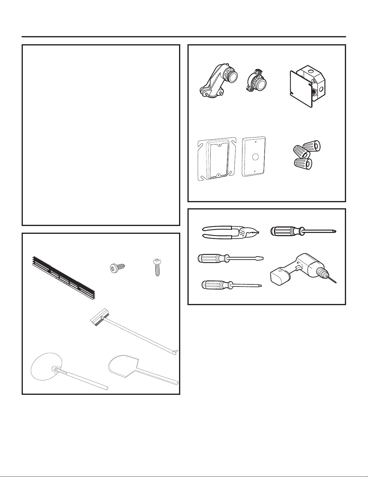
6 31-2001053 Rev. 0
Información de instalación
PARTES INCLUIDAS
(la apariencia puede variar)
ANTES DE EMPEZAR
Lea estas instrucciones cuidadosa y completamente.
• IMPORTANTE — Guarde estas instrucciones
y téngalas disponibles para el inspector local.
• IMPORTANTE — Cumpla con todos los
códigos y ordenanzas vigentes.
• Nota al instalador – Cerciórese de dejar estas
instrucciones con el propietario.
• Nota al consumidor – Guarde estas instrucciones para
usarlas como referencia en el futuro.
• La instalación apropiada es responsabilidad del instalador
y la falla del producto por una instalación incorrecta NO
está cubierta por la garantía.
• Nota – Este aparato debe estar conectado a tierra
adecuadamente.
• ¡ATENCIÓN AL INSTALADOR!
Todos los hornos electrónicos de pared deben ser
cableados directamente en una caja de conexión
aprobada. Un “enchufe-receptáculo” NO ES permitido en
estos productos.
MATERIALES NECESARIOS
HERRAMIENTAS NECESARIAS
Abrazadera de alivio de presión
para conducto de 1/2”
Anillo de Yeso y
Tapa (Opción 1)
Alicates pelacables
Caja de conexión
(Profundidad Máx. de 1 ½)
Destornillador de
estrella #2
Destornillador
con punta plana
Taladro y broca de 3/32”
Tuercas para alambres
Opción 1
Opción 2
Destornillador Torx T20
Cepillo
Paleta Metálica
Ensamble de la
Parrilla Superior
Parrilla
Inferior
Paleta de
Madera
Torx T20 de ½”
para Parrilla
Superior e
Inferior (8)
Tornillos
Phillips de
3/4” (2)
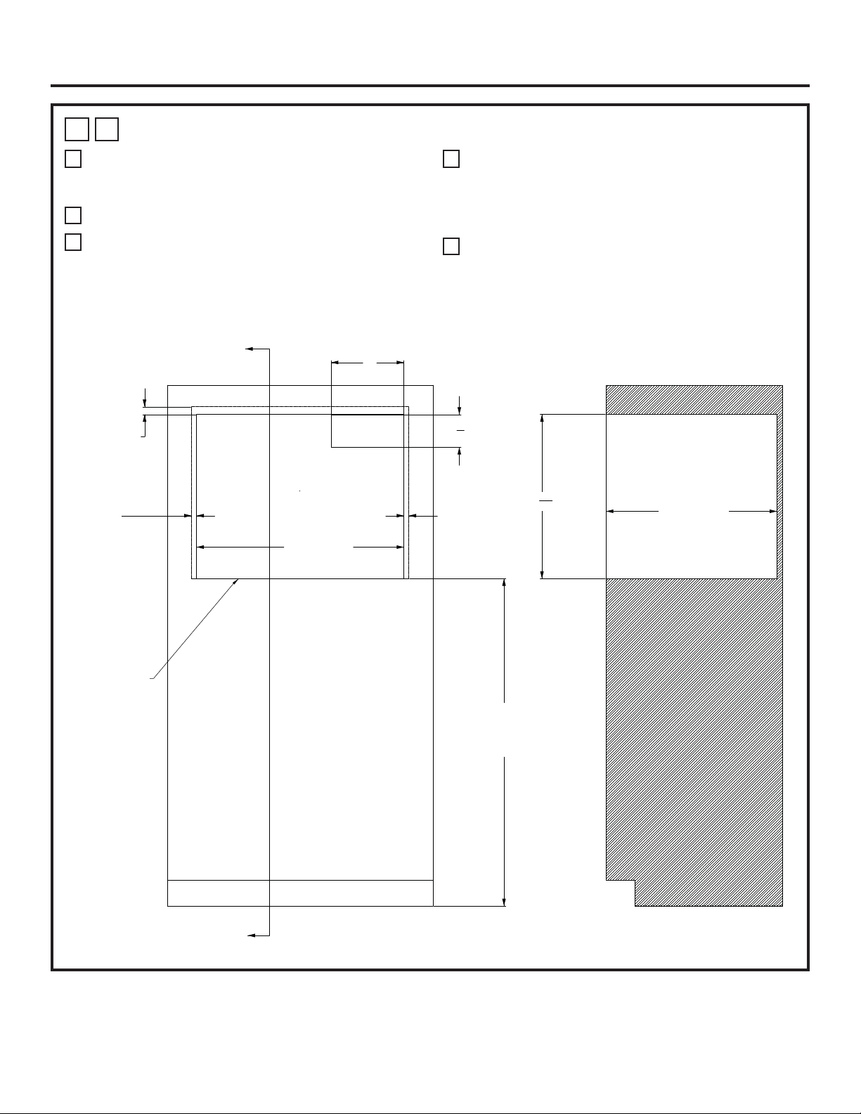
31-2001053 Rev. 0 7
Instalacións
1
A
HORNO DE HOGAR - INSTALACIÓN ESTÁNDAR
A
45” es la altura de instalación mínima requerida. El
horno podrá ser instalado más arriba, dependiendo de la
preferencia del propietario.
B
La plataforma deberá poder soportar 200 libras (91 kg).
C
Se requiere un cerramiento sólido en las partes superior,
inferior, izquierda, derecha y trasera. La superficie trasera
podrá ser de yeso. Se recomienda el uso de técnicas
de fabricación y ensamble avanzadas, a fin de asegurar
un grado preciso de nivelación y paralelismo de los
gabinetes.
D
Ubicación de la caja de empalmes: Deberá estar nivelado
con la superficie trasera de modo que no se extienda
sobre la profundidad del gabinete de 23-1/2 pulgadas. La
caja de empalmes podrá estar ubicada en un gabinete
adyacente.
E
Se podrá lograr un aspecto nivelado en relación
a la puerta del gabinete y el frente de los cajones
circundantes. Se recomienda el uso de un perfil de
un mínimo de 1/8” MÁS ALLÁ de las dimensiones de
SUPERPOSICIÓN.
ELEC
10"
4
1
2
"
SUPERPOSICIÓN
DE 11/16”
SUPERPOSICIÓN
DE 1 1/16”
SUPERPOSICIÓN
DE 11/16”
PLATAFORMA CON
UN MÍNIMO DE 45” DESDE
EL PISO HASTA EL HORNO
A
A
SECCIÓN A-A
ANCHO DEL ESPACIO
LIBRE DE 28 ½”
SIN SUPERPOSICIÓN
CON EL HORNO INFERIOR
22
9
16
"
PROFUNDIDAD
DE GABINETE
DE 23 ½”
LEA LA NOTA D
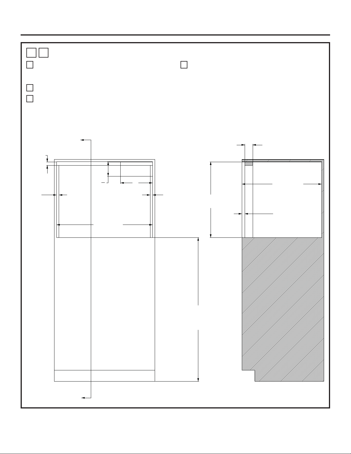
8 31-2001053 Rev. 0
Instalacións
1
B
HORNO DE HOGAR – INSTALACIÓN CON MONTAJE AL RAS
A
45” es la altura de instalación mínima requerida. El
horno podrá ser instalado más arriba, dependiendo de la
preferencia del propietario.
B
La plataforma deberá poder soportar 200 libras (91 kg).
C
Se requiere un cerramiento sólido en las partes superior,
inferior, izquierda, derecha y trasera. La superficie trasera
podrá ser de yeso. Se recomienda el uso de técnicas
de fabricación y ensamble avanzadas, a fin de asegurar
un grado preciso de nivelación y paralelismo de los
gabinetes.
D
Ubicación de la caja de empalmes: Deberá estar nivelado
con la superficie trasera de modo que no se extienda
sobre la profundidad del gabinete de 24-15/16 pulgadas.
La caja de empalmes podrá estar ubicada en un gabinete
adyacente.
ELEC
B
B
SECCIÓN B-B
10"
4
1
2
"
PLATAFORMA CON
UN MÍNIMO DE 45” DESDE
EL PISO HASTA EL HORNO
ANCHO DEL ESPACIO
LIBRE DE 30”
SOPORTE
DE 1 1/8”
SOPORTE
DE 3/4”
ALTURA DEL ESPACIO
LIBRE DE 23 11/16”
PROFUNDIDAD
DEL GABINETE
DE 24 15/16”
REVERSO DEL SOPORTE
DE 7/8”
PROFUNDIDAD
DEL SOPORTE
DE 2-1/2”:
LEA LA NOTA D
SOPORTE
DE 3/4”

31-2001053 Rev. 0 9
1
C
HORNO DE HOGAR SOBRE HORNO DE PARED – INSTALACIÓN ESTÁNDAR CON
ESPACIO LIBRE INTERMEDIO MÍNIMO
A
45” es la altura de instalación mínima requerida. El
horno podrá ser instalado más arriba, dependiendo de la
preferencia del propietario.
B
La Plataforma del Horno de Hogar deberá poder soportar
200 libras (91 kg.). Para esta instalación, se recomienda
enfáticamente bloquear la plataforma dentro de las
paredes laterales, usando uniones de carpintería tipo
Dado. También se recomienda el uso de sujetadores
y pegamento para madera, a fin de reforzar aún más
las uniones de carpintería. La veta de la madera de la
plataforma se deberá orientar de izquierda a derecha.
El borde frontal de la plataforma deberá poseer una
superficie con acabado. Para consultar sobre conceptos
de uniones, lea las ilustraciones 1Q y 1R.
C
Se requiere un cerramiento sólido en las partes superior,
inferior, izquierda, derecha y trasera. La superficie trasera
podrá ser de yeso. Se recomienda el uso de técnicas
de fabricación y ensamble avanzadas, a fin de asegurar
un grado preciso de nivelación y paralelismo de los
gabinetes.
D
Ubicación de la caja de empalmes: Deberá estar nivelado
con la superficie trasera de modo que no se extienda
sobre la profundidad del gabinete de 23-1/2 pulgadas. La
caja de empalmes podrá estar ubicada en un gabinete
adyacente.
E
Se recomienda el uso de un perfil de 1/8” MÁS ALLÁ de
las dimensiones de SUPERPOSICIÓN, a fin de contar
con un espacio libre para el desplazamiento del cajón y la
puerta.
F
Se podrán agregar soportes exteriores sobre los laterales
y la parte superior de la abertura del Horno de Hogar,
a fin de poder alinear la superficie frontal del Horno
de Hogar con la superficie frontal del horno de pared
que se encuentra debajo. El acabado será acorde con
los requisitos del cliente. Un acabado negro liso podrá
combinar mejor con el aspecto lateral del horno que se
encuentra debajo.
G
Para el HORNO DE PARED INFERIOR, se recomienda
un MARCO CON VENTILACIÓN INFERIOR de aluminio
extrudido. Los modelos de horno de pared que comienzan
con “ZTSX” ya incluyen el marco de ventilación de
aluminio. Para los modelos que comienzan con “ZTS”, se
deberá ordenar el kit del marco de ventilación ZX30VT1,
que incluye el marco de ventilación de aluminio y las
herramientas de montaje. De forma alternativa, el marco
de acero inoxidable suministrado con todos los modelos
se podrá usar para esta configuración de gabinetes.
Asegúrese de ajustar la dimensión de “superposición”
asociada con el marco de acero inoxidable. Antes
cualquier duda, por favor comuníquese al 1-800-626-2000.
H
La dimensión de la línea central de abertura se toma
sobre la ABERTURA FRONTAL de cada cerramiento.
Instalacións
ELEC
ELEC
PLATAFORMA DEL HORNO DE HOGAR
LEA LA NOTA B
10"
4
1
2
"
9
1
2
"
5
1
4
"
SUPERPOSICIÓN
DE 11/16”
SUPERPOSICIÓN
DE 11/16”
SUPERPOSICIÓN
DE 1 1/16”
SUPERPOSICIÓN
DE 3/16”
LEA LA NOTA G
A
A
SECCIÓN A-A
MÍN. DE 25 13/16”
C
L
A
C
L
LEA LA NOTA H
ANCHO
DEL ESPACIO
LIBRE DE 28-1/2”
ANCHO DEL ESPACIO
LIBRE DE 28 ½”
MÍN. DE 45”
7
8
"
LEA LA NOTA F
1
2
"
LEA LA NOTA F
1
2
"
LEA LA NOTA F
22
9
16
"
27
5
8
"
PROFUNDIDAD
DE GABINETE
DE 23-1/2”
MÍN. DE 23/32”
“CONTRACHAPADO
DE ¾”
7
16
"
LEA LA NOTA F
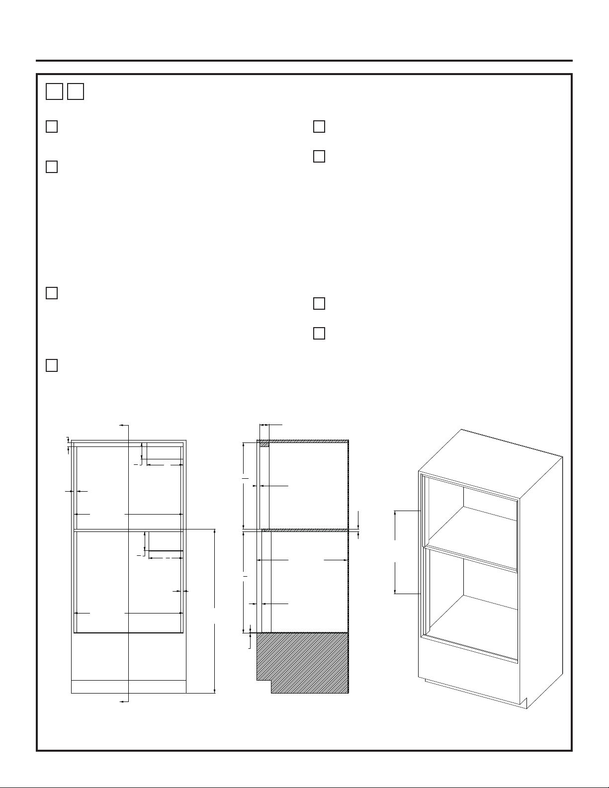
10 31-2001053 Rev. 0
Instalacións
1
D
HORNO DE HOGAR SOBRE HORNO DE PARED – INSTALACIÓN CON MONTAJE
AL RAS CON ESPACIO LIBRE INTERMEDIO MÍNIMO
A
45” es la altura de instalación mínima requerida. El
horno podrá ser instalado más arriba, dependiendo de la
preferencia del propietario.
B
La Plataforma del Horno de Hogar deberá poder soportar
200 libras (91 kg.). Para esta instalación, se recomienda
enfáticamente bloquear la plataforma dentro de las
paredes laterales, usando uniones de carpintería tipo
Dado. También se recomienda el uso de sujetadores
y pegamento para madera, a fin de reforzar aún más
las uniones de carpintería. La veta de la madera de la
plataforma se deberá orientar de izquierda a derecha.
El borde frontal de la plataforma deberá poseer una
superficie con acabado. Para consultar sobre conceptos
de uniones, lea las ilustraciones 1Q y 1R.
C
Se requiere un cerramiento sólido en las partes superior,
inferior, izquierda, derecha y trasera. La superficie trasera
podrá ser de yeso. Se recomienda el uso de técnicas
de fabricación y ensamble avanzadas, a fin de asegurar
un grado preciso de nivelación y paralelismo de los
gabinetes.
D
Ubicación de la caja de empalmes: Deberá estar nivelado
con la superficie trasera de modo que no se extienda
sobre la profundidad del gabinete de 24-15/16 pulgadas.
La caja de empalmes podrá estar ubicada en un gabinete
adyacente.
E
La base frontal de los soportes interiores deberán poseer
un acabado de su superficie.
F
El Horno de Pared REQUIERE un MARCO DE
VENTILACIÓN INFERIOR de aluminio extrudido. Los
modelos de horno de pared que comienzan con “ZTSX”
ya incluyen el marco de ventilación de aluminio. Para los
modelos que comienzan con “ZTS”, se deberá ordenar
el kit del marco de ventilación ZX30VT1, que incluye
el marco de ventilación de aluminio y las herramientas
de montaje. De forma alternativa, el marco de acero
inoxidable suministrado con todos los modelos se podrá
usar para esta configuración de gabinetes. Asegúrese
de ajustar la dimensión de “superposición” asociada con
el marco de acero inoxidable. Antes cualquier duda, por
favor comuníquese al 1-800-626-2000.
G
La dimensión de la línea central de abertura se toma
sobre la ABERTURA FRONTAL de cada cerramiento.
H
El soporte de la superficie inferior del Horno de Pared
deberá poseer una tabla de fibra de MDF de un grosor de
1/4” o equivalente.
MÍN. DE 26-1/2”
C
L
A
C
L
LEA LA NOTA G
ELEC.
LEA LA NOTA D
ELEC.
LEA LA NOTA D
PLATAFORMA DEL HORNO DE HOGAR
LEA LA NOTA B
10"
4
1
2
"
9
1
2
"
5
1
4
"
SOPORTE
DE 1 1/8”
SOPORTE
DE 3/4”
SOPORTE
DE ¾”
ANCHO DEL ESPACIO
LIBRE DE 30”
ANCHO DEL
ESPACIO LIBRE
DE 30”
MÍN.
DE 45”
PROFUNDIDAD
DEL GABINETE
DE 24 15/16”
REVERSO DEL SOPORTE
DEL HORNO DE HOGAR
DE 7/8”
PROFUNDIDAD
DEL SOPORTE DE 2 ½”
REVERSO DEL SOPORTE
DEL HORNO DE PARED
DE 1 7/16
MIN. DE 23/32”
“CONTRACHAPADO
DE ¾”
MDF DE 1/4”
LEA LA NOTA H
23
11
16
"
27
7
8
"
SECCIÓN A-A
A
A

31-2001053 Rev. 0 11
Instalacións
1
E
HORNO DE HOGAR SOBRE HORNO DE PARED – INSTALACIÓN ESTÁNDAR CON
PLATAFORMA INTERMEDIA DE 2”
A
45” es la altura de instalación mínima requerida. El
horno podrá ser instalado más arriba, dependiendo de la
preferencia del propietario.
B
La Plataforma del Horno de Hogar deberá poder soportar
200 libras (91 kg.).
C
Se requiere un cerramiento sólido en las partes superior,
inferior, izquierda, derecha y trasera. La superficie trasera
podrá ser de yeso. Se recomienda el uso de técnicas
de fabricación y ensamble avanzadas, a fin de asegurar
un grado preciso de nivelación y paralelismo de los
gabinetes.
D
Ubicación de la caja de empalmes: berá estar nivelado
con la superficie trasera de modo que no se extienda
sobre la profundidad del gabinete de 23-1/2 pulgadas. La
caja de empalmes podrá estar ubicada en un gabinete
adyacente.
E
Se recomienda el uso de un perfil de 1/8” MÁS ALLÁ de
las dimensiones de SUPERPOSICIÓN, a fin de contar
con un espacio libre para el desplazamiento del cajón y la
puerta.
F
Se podrán agregar soportes exteriores sobre los laterales
y la parte superior de la abertura del Horno de Hogar,
a fin de poder alinear la superficie frontal del Horno
de Hogar con la superficie frontal del horno de pared
que se encuentra debajo. El acabado será acorde con
los requisitos del cliente. Un acabado negro liso podrá
combinar mejor con el aspecto lateral del horno que se
encuentra debajo.
G
Para el HORNO DE PARED INFERIOR, se recomienda
un MARCO CON VENTILACIÓN INFERIOR de aluminio
extrudido. Los modelos de horno de pared que comienzan
con “ZTSX” ya incluyen el marco de ventilación de
aluminio. Para los modelos que comienzan con “ZTS”, se
deberá ordenar el kit del marco de ventilación ZX30VT1,
que incluye el marco de ventilación de aluminio y las
herramientas de montaje. De forma alternativa, el marco
de acero inoxidable suministrado con todos los modelos
se podrá usar para esta configuración de gabinetes.
Asegúrese de ajustar la dimensión de “superposición”
asociada con el marco de acero inoxidable. Antes
cualquier duda, por favor comuníquese al 1-800-626-2000.
H
La dimensión de la línea central de abertura se toma
sobre la ABERTURA FRONTAL de cada cerramiento.
ELEC.
LEA LA NOTA D
ELEC.
LEA LA NOTA D
PLATAFORMA DEL HORNO DE HOGAR
LEA LA NOTA B
4
1
2
"
10"
5
1
4
"
9
1
2
"
SUPERPOSICIÓN
DE 1 1/16”
SUPERPOSICIÓN
DE 11/16”
SUPERPOSICIÓN
DE 3/16”
LEA LA NOTA G
SUPERPOSICIÓN
DE 11/16”
SUPERPOSICIÓN
DE 1”
A
A
SECCIÓN A-A
27
3
32
"
C
L
A
C
L
LEA LA NOTA H
7
8
"
LEA LA NOTA F
ANCHO DEL ESPACIO
LIBRE DE 28 ½”
1
2
"
LEA LA NOTA F
1
2
"
LEA LA NOTA F
ANCHO DEL ESPACIO
LIBRE DE 28 ½”
MÍN. DE 45”
22
9
16
"
7
16
"
LEA LA NOTA F
2” ENTRE
ESPACIOS
LIBRES
27
5
8
"
PROFUNDIDAD
DE GABINETE
DE 23 ½”
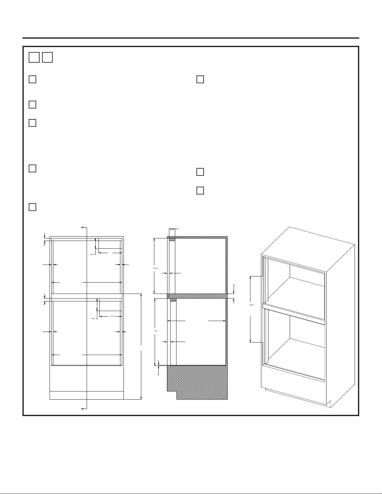
12 31-2001053 Rev. 0
Instalacións
1
F
HORNO DE HOGAR SOBRE HORNO DE PARED – INSTALACIÓN CON MONTAJE
AL RAS CON PLATAFORMA INTERMEDIA DE 2”
A
45” es la altura de instalación mínima requerida. El
horno podrá ser instalado más arriba, dependiendo de la
preferencia del propietario.
B
La Plataforma del Horno de Hogar deberá poder soportar
200 libras (91 kg.).
C
Se requiere un cerramiento sólido en las partes superior,
inferior, izquierda, derecha y trasera. La superficie trasera
podrá ser de yeso. Se recomienda el uso de técnicas
de fabricación y ensamble avanzadas, a fin de asegurar
un grado preciso de nivelación y paralelismo de los
gabinetes.
D
Ubicación de la caja de empalmes: Deberá estar nivelado
con la superficie trasera de modo que no se extienda
sobre la profundidad del gabinete de 24-15/16 pulgadas.
La caja de empalmes podrá estar ubicada en un gabinete
adyacente.
E
La base frontal de los soportes interiores deberán poseer
un acabado de su superficie.
F
El Horno de Pared REQUIERE un MARCO DE
VENTILACIÓN INFERIOR de aluminio extrudido. Los
modelos de horno de pared que comienzan con “ZTSX”
ya incluyen el marco de ventilación de aluminio. Para los
modelos que comienzan con “ZTS”, se deberá ordenar
el kit del marco de ventilación ZX30VT1, que incluye
el marco de ventilación de aluminio y las herramientas
de montaje. De forma alternativa, el marco de acero
inoxidable suministrado con todos los modelos se podrá
usar para esta configuración de gabinetes. Asegúrese
de ajustar la dimensión de “superposición” asociada con
el marco de acero inoxidable. Antes cualquier duda, por
favor comuníquese al 1-800-626-2000
G
La dimensión de la línea central de abertura se toma
sobre la ABERTURA FRONTAL de cada cerramiento.
H
El soporte de la superficie inferior del Horno de Pared
deberá poseer una tabla de fibra de MDF de un grosor de
1/4” o equivalente.
ELEC.
LEA LA NOTA D
ELEC.
LEA LA NOTA D
PLATAFORMA DEL HORNO DE HOGAR
LEA LA NOTA B
4
1
2
"
10"
5
1
4
"
9
1
2
"
A
A
28
5
32
"
C
L
A
C
L
LEA LA NOTA G
PROFUNDIDAD
DEL GABINETE
DE 24 15/16”
SECCIÓN A-A
SOPORTE
DE 3/4”
SOPORTE
DE 3/4”
SOPORTE
DE 3/4”
SOPORTE
DE 1 1/8”
SOPORTE
DE 1 1/8”
MÍN. DE 45”
ANCHO
DEL ESPACIO
LIBRE DE 30”
30"
CUTOUT WIDTH
23
11
16
"
REVERSO DEL SOPORTE
DEL HORNO DE HOGAR DE 7/8”
28
5
8
"
REVERSO DEL SOPORTE
DEL HORNO DE PARED
DE 1 7/16”
SOPORTE
DE MDF DE 1/4”
LEA LA NOTA H
PROFUNDIDAD
DEL SOPORTE DE 2-1/2”
2” ENTRE
ESPACIOS
LIBRES
SOPORTE
DE 3/4”
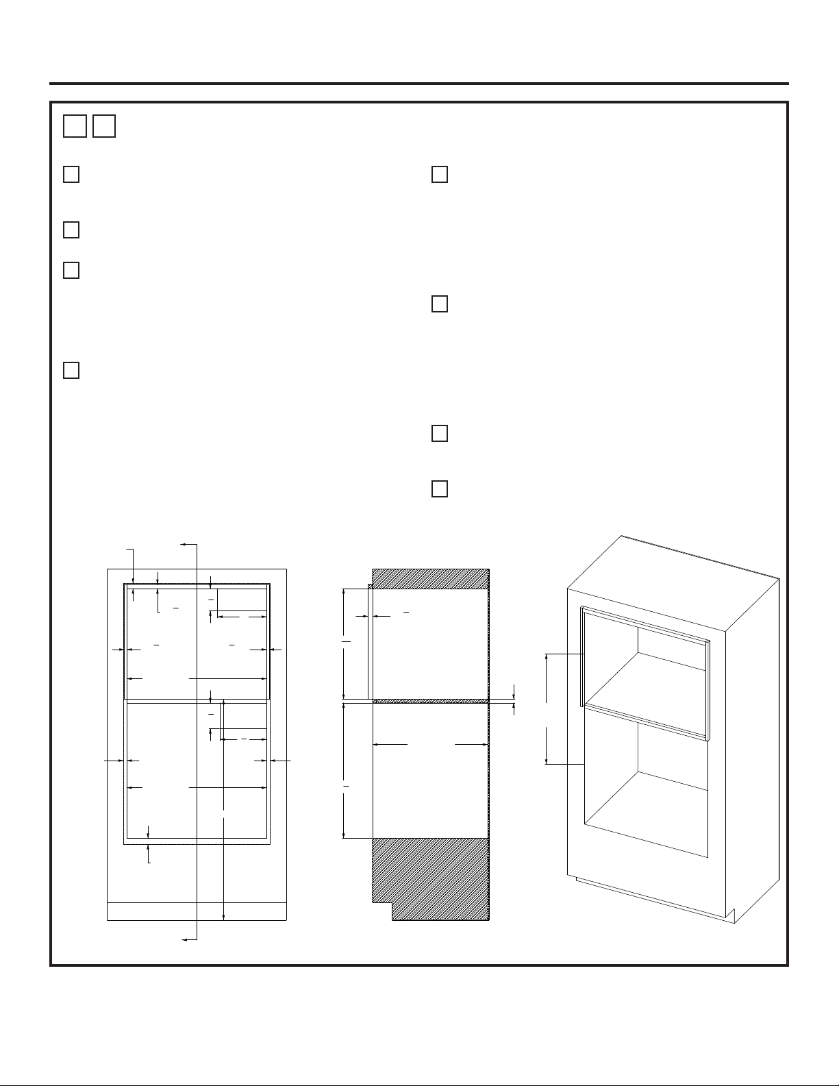
31-2001053 Rev. 0 13
1
G
HORNO DE HOGAR SOBRE HORNO DE PARED CON PUERTA FRANCESA –
INSTALACIÓN ESTÁNDAR CON ESPACIO LIBRE INTERMEDIO MÍNIMO
A
45” es la altura de instalación mínima requerida. El
horno podrá ser instalado más arriba, dependiendo de la
preferencia del propietario.
B
La Plataforma del Horno de Hogar deberá poder soportar
200 libras (91 kg.).
C
Se requiere un cerramiento sólido en las partes superior,
inferior, izquierda, derecha y trasera. La superficie trasera
podrá ser de yeso. Se recomienda el uso de técnicas
de fabricación y ensamble avanzadas, a fin de asegurar
un grado preciso de nivelación y paralelismo de los
gabinetes.
D
Ubicación de la caja de empalmes: Deberá estar nivelado
con la superficie trasera de modo que no se extienda
sobre la profundidad del gabinete de 23-1/2 pulgadas. La
caja de empalmes podrá estar ubicada en un gabinete
adyacente.
E
Se recomienda el uso de un perfil de 1/8” MÁS ALLÁ de
las dimensiones de SUPERPOSICIÓN, a fin de contar
con un espacio libre para el desplazamiento del cajón y
la puerta. Para el HORNO DE PARED CON PUERTA
FRANCESA Inferior, por favor consulte las restricciones
de apertura de puerta asociadas con encimeras, paredes
y frente de gabinetes cercanos, a fin de ajustar las
superposiciones.
F
Se podrán agregar soportes exteriores sobre los laterales
y la parte superior de la abertura del Horno de Hogar,
a fin de poder alinear la superficie frontal del Horno
de Hogar con la superficie frontal del horno de pared
que se encuentra debajo. El acabado será acorde con
los requisitos del cliente. Un acabado negro liso podrá
combinar mejor con el aspecto lateral del horno que se
encuentra debajo.
G
Para el HORNO DE PARED CON PUERTA FRANCESA,
el MARCO INFERIOR de acero inoxidable suministrado
con la unidad es la única opción.
H
La dimensión de la línea central de abertura se toma
sobre la ABERTURA FRONTAL de cada cerramiento.
Instalacións
ELEC
ELEC
PLATAFORMA DEL HORNO DE HOGAR
LEA LA NOTA B
10"
4
1
2
"
9
1
2
"
5
1
4
"
SUPERPOSICIÓN
DE 11/16”
LEA LA NOTA E
LEA LA NOTA E
SUPERPOSICIÓN
DE 11/16”
SUPERPOSICIÓN
DE 1 1/16”
SUPERPOSICIÓN
DE 1 1/4”
A
A
SECCIÓN A-A
MÍN. DE 25 13/16”
C
L
A
C
L
LEA LA NOTA H
ANCHO DEL ESPACIO
LIBRE DE 28 ½”
ANCHO DEL ESPACIO
LIBRE DE 28 ½”
MÍN. DE 45”
7
8
"
LEA LA NOTA F
1
2
"
LEA LA NOTA F
1
2
"
LEA LA NOTA F
MIN. DE 23/32”
CONTRACHAPADO
DE 3/4”
PROFUNDIDAD
DE GABINETE
DE 23 ½”
27
5
8
"
22
9
16
"
7
8
"
LEA LA NOTA F
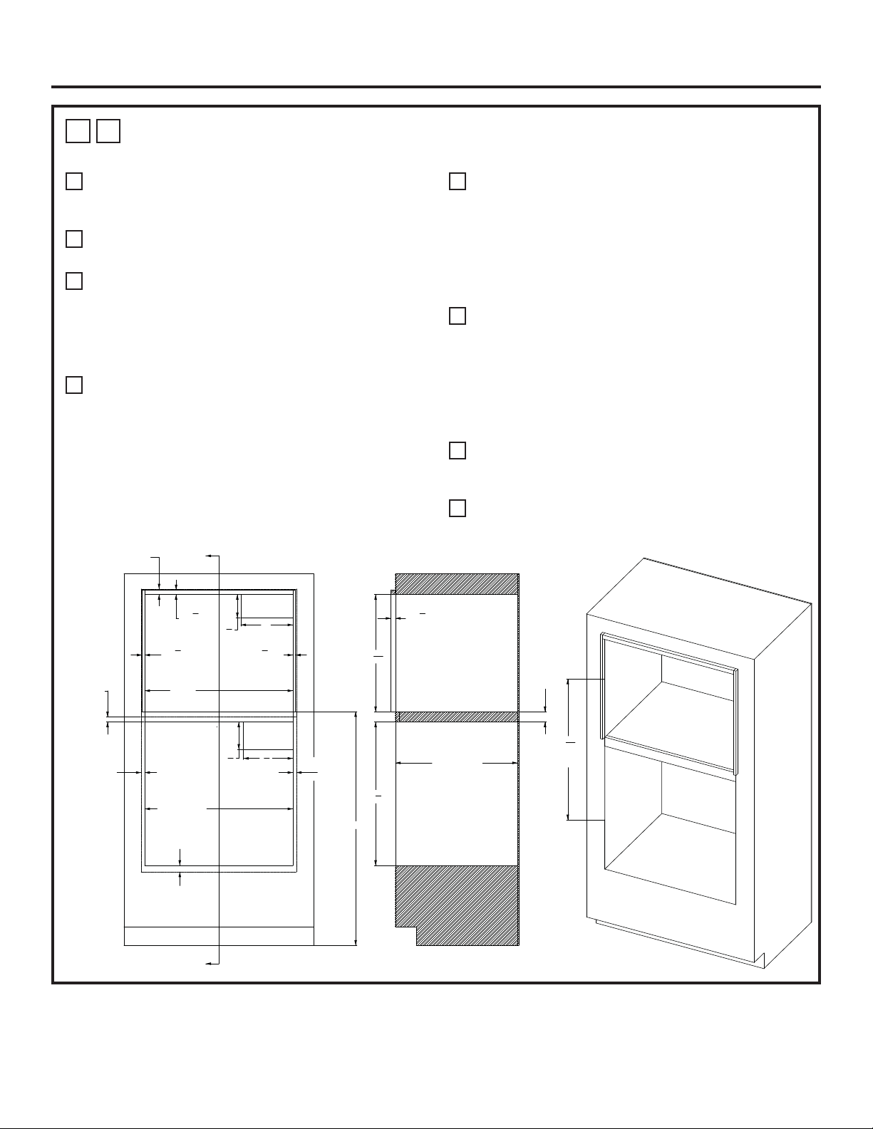
14 31-2001053 Rev. 0
1
H
HORNO DE HOGAR SOBRE HORNO DE PARED CON PUERTA FRANCESA –
INSTALACIÓN ESTÁNDAR CON PLATAFORMA INTERMEDIA DE 2”
A
45” es la altura de instalación mínima requerida. El
horno podrá ser instalado más arriba, dependiendo de la
preferencia del propietario.
B
La Plataforma del Horno de Hogar deberá poder soportar
200 libras (91 kg.).
C
Se requiere un cerramiento sólido en las partes superior,
inferior, izquierda, derecha y trasera. La superficie trasera
podrá ser de yeso. Se recomienda el uso de técnicas
de fabricación y ensamble avanzadas, a fin de asegurar
un grado preciso de nivelación y paralelismo de los
gabinetes.
D
Ubicación de la caja de empalmes: Deberá estar nivelado
con la superficie trasera de modo que no se extienda
sobre la profundidad del gabinete de 23-1/2 pulgadas. La
caja de empalmes podrá estar ubicada en un gabinete
adyacente.
E
Se recomienda el uso de un perfil de 1/8” MÁS ALLÁ de
las dimensiones de SUPERPOSICIÓN, a fin de contar
con un espacio libre para el desplazamiento del cajón y
la puerta. Para el HORNO DE PARED CON PUERTA
FRANCESA Inferior, por favor consulte las restricciones
de apertura de puerta asociadas con encimeras, paredes
y frentes de gabinetes cercanos, a fin de ajustar las
superposiciones.
F
Se podrán agregar soportes exteriores sobre los laterales
y la parte superior de la abertura del Horno de Hogar,
a fin de poder alinear la superficie frontal del Horno
de Hogar con la superficie frontal del horno de pared
que se encuentra debajo. El acabado será acorde con
los requisitos del cliente. Un acabado negro liso podrá
combinar mejor con el aspecto lateral del horno que se
encuentra debajo.
G
Para el HORNO DE PARED CON PUERTA FRANCESA,
el MARCO INFERIOR de acero inoxidable suministrado
con la unidad es la única opción.
H
La dimensión de la línea central de abertura se toma
sobre la ABERTURA FRONTAL de cada cerramiento.
Instalacións
ELEC.
LEA LA NOTA D
ELEC.
LEA LA NOTA D
PLATAFORMA DEL HORNO DE HOGAR
LEA LA NOTA B
4
1
2
"
10"
5
1
4
" 9
1
2
"
SUPERPOSICIÓN
DE 1 1/16”
SUPERPOSICIÓN
DE 11/16”
LEA LA NOTA E
SUPERPOSICIÓN
DE 1-1/4”
SUPERPOSICIÓN
DE 1”
A
A
SECCIÓN A-A
27
3
32
"
C
L
TO
C
L
LEA LA NOTA H
LEA LA NOTA E
SUPERPOSICIÓN
DE 11/16”
7
8
"
LEA LA NOTA F
ANCHO
DEL ESPACIO LIBRE
DE 28 ½”
1
2
"
LEA LA NOTA F
1
2
"
LEA LA NOTA F
ANCHO
DEL ESPACIO LIBRE
DE 28 ½”
MÍN. DE 45”
PROFUNDIDAD
DE GABINETE
DE 23 ½”
27
5
8
"
22
9
16
"
7
8
"
LEA LA NOTA F
2” ENTRE
ESPACIOS
LIBRES
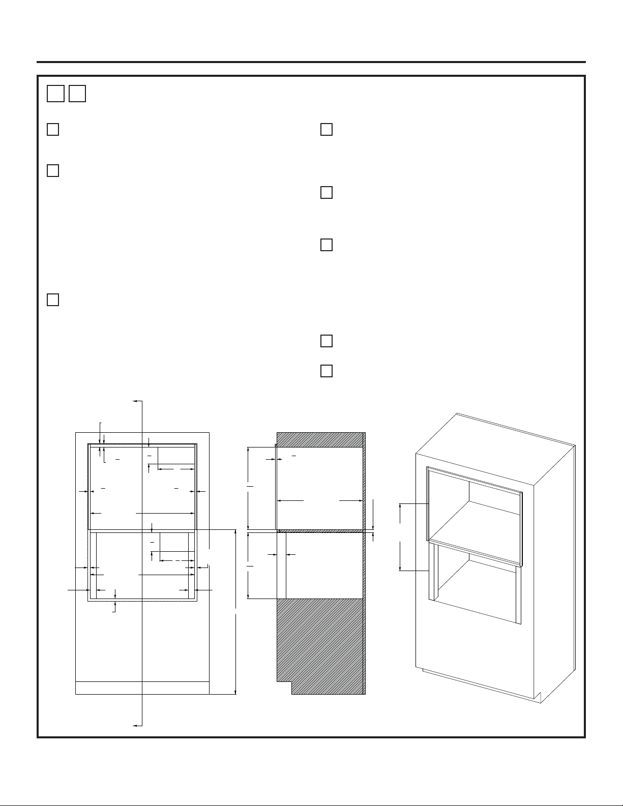
31-2001053 Rev. 0 15
1
I
HORNO DE HOGAR SOBRE HORNO DE VAPOR – INSTALACIÓN ESTÁNDAR CON
ESPACIO LIBRE INTERMEDIO MÍNIMO
A
45” es la altura de instalación mínima requerida. El
horno podrá ser instalado más arriba, dependiendo de la
preferencia del propietario.
B
La Plataforma del Horno de Hogar deberá poder soportar
200 libras (91 kg.). Para esta instalación, se recomienda
enfáticamente bloquear la plataforma dentro de las
paredes laterales, usando uniones de carpintería tipo
Dado. También se recomienda el uso de sujetadores
y pegamento para madera, a fin de reforzar aún más
las uniones de carpintería. La veta de la madera de la
plataforma se deberá orientar de izquierda a derecha.
El borde frontal de la plataforma deberá poseer una
superficie con acabado. Para consultar sobre conceptos
de uniones, lea las ilustraciones 1Q y 1R.
C
Se requiere un cerramiento sólido en las partes superior,
inferior, izquierda, derecha y trasera. La superficie trasera
podrá ser de yeso. Se recomienda el uso de técnicas
de fabricación y ensamble avanzadas, a fin de asegurar
un grado preciso de nivelación y paralelismo de los
gabinetes.
D
Ubicación de la caja de empalmes: Deberá estar nivelado
con la superficie trasera de modo que no se extienda
sobre la profundidad del gabinete de 23-1/2 pulgadas. La
caja de empalmes podrá estar ubicada en un gabinete
adyacente.
E
Se recomienda el uso de un perfil de 1/8” MÁS ALLÁ de
las dimensiones de SUPERPOSICIÓN, a fin de contar
con un espacio libre para el desplazamiento del cajón y la
puerta.
F
Se podrán agregar soportes exteriores sobre los laterales
y la parte superior de la abertura del Horno de Hogar,
a fin de poder alinear la superficie frontal del Horno
de Hogar con la superficie frontal del horno de pared
que se encuentra debajo. El acabado será acorde con
los requisitos del cliente. Un acabado negro liso podrá
combinar mejor con el aspecto lateral del horno que se
encuentra debajo.
G
La opción de un MARCO DE VENTILACIÓN INFERIOR
NO está disponible para esta configuración de gabinetes.
H
La dimensión de la línea central de abertura se toma
sobre la ABERTURA FRONTAL de cada cerramiento.
Instalacións
ELEC
LEA LA NOTA D
PLATAFORMA DEL HORNO DE HOGAR
LEA LA NOTA B
ELEC
4
1
2
"
10"
SUPERPOSICIÓN
DE 1 1/16”
SUPERPOSICIÓN
DE 3/4”
SUPERPOSICIÓN
DE 11/16”
SUPERPOSICIÓN
DE 11/16”
9
1
2
"
5
1
4
"
A
A
MÍN. DE 21 3/64"
C
L
A
C
L
LEA LA NOTA H
SECCIÓN A-A
7
8
"
LEA LA NOTA F
1
2
"
LEA LA NOTA F
1
2
"
LEA LA NOTA F
ANCHO
DEL ESPACIO
LIBRE DE 28-1/2”
SOPORTE
DE 1 5/8”
SOPORTE
DE 1 5/8”
MÍN. DE 45”
ANCHO
DEL ESPACIO
LIBRE DE 28-1/2”
1
2
"
LEA LA NOTA F
22
9
16
"
PROFUNDIDAD
DE GABINETE
DE 23-1/2”
18
3
32
"
PROFUNDIDAD
DE SOPORTE
DE 2-1/2”
MIN. DE 23/32”
CONTRACHAPADO
DE 3/4”
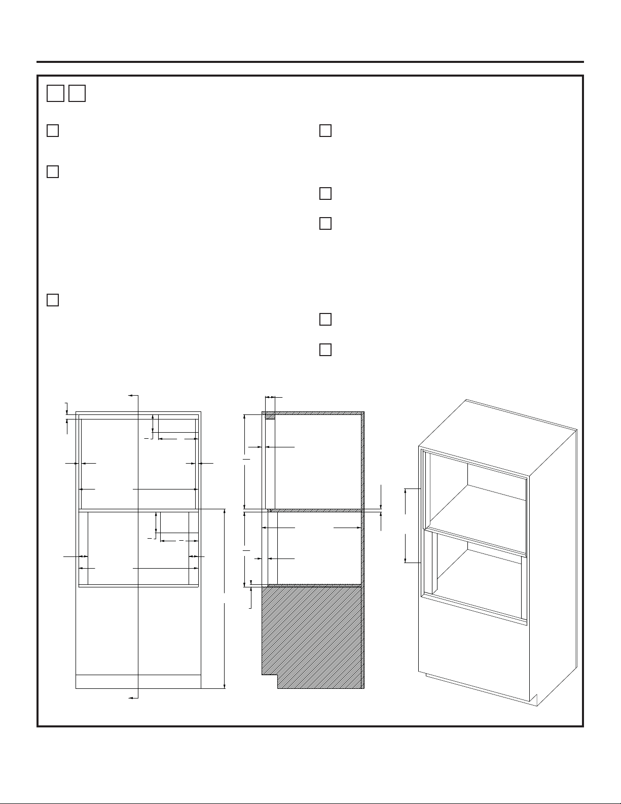
16 31-2001053 Rev. 0
1
J
HORNO DE HOGAR SOBRE HORNO DE VAPOR – INSTALACIÓN CON
MONTAJE AL RAS CON ESPACIO LIBRE INTERMEDIO MÍNIMO
A
45” es la altura de instalación mínima requerida. El
horno podrá ser instalado más arriba, dependiendo de la
preferencia del propietario.
B
La Plataforma del Horno de Hogar deberá poder soportar
200 libras (91 kg.). Para esta instalación, se recomienda
enfáticamente bloquear la plataforma dentro de las
paredes laterales, usando uniones de carpintería tipo
Dado. También se recomienda el uso de sujetadores
y pegamento para madera, a fin de reforzar aún más
las uniones de carpintería. La veta de la madera de la
plataforma se deberá orientar de izquierda a derecha.
El borde frontal de la plataforma deberá poseer una
superficie con acabado. Para consultar sobre conceptos
de uniones, lea las ilustraciones 1Q y 1R.
C
Se requiere un cerramiento sólido en las partes superior,
inferior, izquierda, derecha y trasera. La superficie trasera
podrá ser de yeso. Se recomienda el uso de técnicas
de fabricación y ensamble avanzadas, a fin de asegurar
un grado preciso de nivelación y paralelismo de los
gabinetes.
D
Ubicación de la caja de empalmes: Deberá estar nivelado
con la superficie trasera de modo que no se extienda
sobre la profundidad del gabinete de 24-15/16 pulgadas.
La caja de empalmes podrá estar ubicada en un gabinete
adyacente.
E
La base frontal de los soportes interiores deberán poseer
un acabado de su superficie.
F
Se podrá instalar un KIT DE MARCOS INFERIOR
opcional con un cambio de altura para la ABERTURA
DEL ESPACIO LIBRE Y SOPORTE INFERIOR. El kit
de marcos ZXSTEAM1 se podrá usar con una altura de
ABERTURA DEL ESPACIO LIBRE de 19 25/32” y una
altura del SOPORTE INFERIOR de 1 5/8”.
Ante cualquier duda, por favor comuníquese al 1-800-626-
2000.
G
La dimensión de la línea central de abertura se toma
sobre la ABERTURA FRONTAL de cada cerramiento.
H
El soporte de la superficie inferior del Horno de Vapor
deberá poseer una tabla de fibra de MDF de un grosor de
5/8” o equivalente.
Instalacións
ELEC.
LEA LA NOTA D
ELEC.
PLATAFORMA DEL HORNO DE HOGAR
LEA LA NOTA B
PLATAFORMA DEL HORNO DE VAPOR
LEA LA NOTA H
10"
4
1
2
"
9
1
2
"
5
1
4
"
A
A
SECCIÓN A-A
SOPORTE
DE 1-1/8”
SOPORTE
DE 3/4”
SOPORTE
DE 3/4”
SOPORTE
DE 2-3/8”
SOPORTE
DE 2 -3/8”
ANCHO DEL ESPACIO
LIBRE DE 30”
ANCHO DEL ESPACIO
LIBRE DE 30”
MÍN. DE 45”
MÍN. DE 21 61/64"
C
L
A
C
L
LEA LA NOTA G
PROFUNDIDAD DEL SOPORTE DE 2-1/2”
REVERSO DEL SOPORTE
DEL HORNO DE HOGAR
DE 7/8”
23
11
16
"
MDF
DE 5/8”
LEA LA NOTA H
18
25
32
"
PROFUNDIDAD DEL GABINETE
DE 24 15/16”
REVERSO DEL SOPORTE
DEL HORNO DE VAPOR DE 1-1/2”
MIN. DE 23/32”
“CONTRACHAPADO DE 3/4”
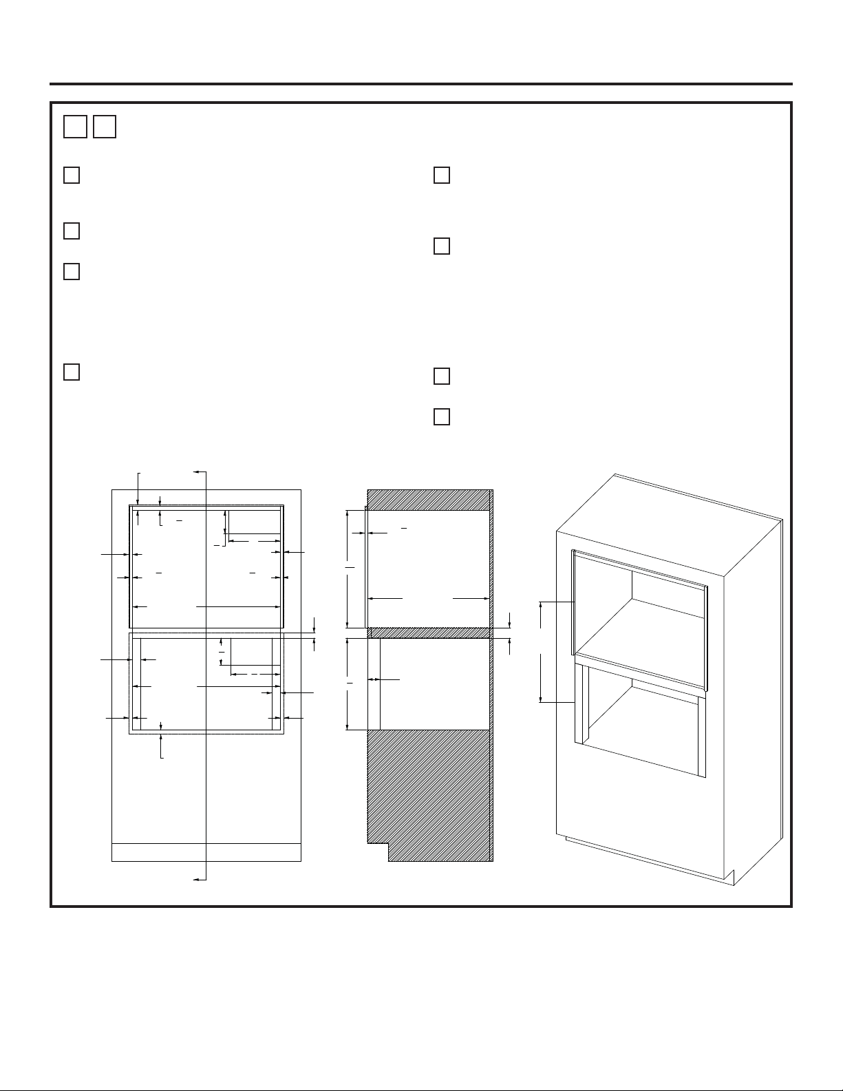
31-2001053 Rev. 0 17
1
K
HORNO DE HOGAR SOBRE HORNO DE VAPOR – INSTALACIÓN ESTÁNDAR CON
PLATAFORMA INTERMEDIA DE 2”
A
45” es la altura de instalación mínima requerida. El
horno podrá ser instalado más arriba, dependiendo de la
preferencia del propietario.
B
La Plataforma del Horno de Hogar deberá poder soportar
200 libras (91 kg.).
C
Se requiere un cerramiento sólido en las partes superior,
inferior, izquierda, derecha y trasera. La superficie trasera
podrá ser de yeso. Se recomienda el uso de técnicas
de fabricación y ensamble avanzadas, a fin de asegurar
un grado preciso de nivelación y paralelismo de los
gabinetes.
D
Ubicación de la caja de empalmes: Deberá estar nivelado
con la superficie trasera de modo que no se extienda
sobre la profundidad del gabinete de 23-1/2 pulgadas. La
caja de empalmes podrá estar ubicada en un gabinete
adyacente.
E
Se recomienda el uso de un perfil de 1/8” MÁS ALLÁ de
las dimensiones de SUPERPOSICIÓN, a fin de contar
con un espacio libre para el desplazamiento del cajón y la
puerta.
F
Se podrán agregar soportes exteriores sobre los laterales
y la parte superior de la abertura del Horno de Hogar,
a fin de poder alinear la superficie frontal del Horno
de Hogar con la superficie frontal del horno de pared
que se encuentra debajo. El acabado será acorde con
los requisitos del cliente. Un acabado negro liso podrá
combinar mejor con el aspecto lateral del horno que se
encuentra debajo.
G
La opción de un MARCO DE VENTILACIÓN INFERIOR
NO está disponible para esta configuración de gabinetes.
H
La dimensión de la línea central de abertura se toma
sobre la ABERTURA FRONTAL de cada cerramiento.
Instalacións
ELEC.
LEA LA NOTA D
ELEC.
LEA LA NOTA D
PLATAFORMA DEL HORNO DE HOGAR
LEA LA NOTA B
4
1
2
"
10"
5
1
4
"
9
1
2
"
SUPERPOSICIÓN
DE 3/4”
SUPERPOSICIÓN
DE 1”
SUPERPOSICIÓN
DE 11/16”
SUPERPOSICIÓN
DE 11/16”
SUPERPOSICIÓN
DE 1 1/16”
7
8
"
LEA LA NOTA F
1
2
"
LEA LA NOTA F
1
2
"
LEA LA NOTA F
ANCHO DEL ESPACIO
LIBRE DE 28-1/2”
ANCHO DEL ESPACIO
LIBRE DE 28-1/2”
SOPORTE
DE 1-5/8”
SOPORTE
DE 1-5/8”
1
2
"
LEA LA NOTA F
22
9
16
"
17
3
4
"
2” ENTRE
ESPACIOS
LIBRES
PROFUNDIDAD
DE GABINETE DE 23-1/2”
PROFUNDIDAD
DEL SOPORTE DE 2-1/2”
SECCIÓN A-A
22 5/32"
C
L
A
C
L
LEA LA NOTA H
SUPERPOSICIÓN
DE 11/16”
SUPERPOSICIÓN
DE 11/16”
A
A
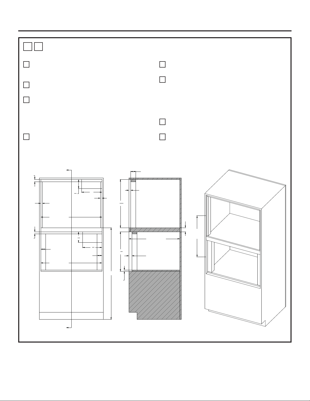
18 31-2001053 Rev. 0
1
L
HORNO DE HOGAR SOBRE HORNO DE VAPOR – INSTALACIÓN CON MONTAJE
AL RAS CON PLATAFORMA INTERMEDIA DE 2”
A
45” es la altura de instalación mínima requerida. El
horno podrá ser instalado más arriba, dependiendo de la
preferencia del propietario.
B
La Plataforma del Horno de Hogar deberá poder soportar
200 libras (91 kg.).
C
Se requiere un cerramiento sólido en las partes superior,
inferior, izquierda, derecha y trasera. La superficie trasera
podrá ser de yeso. Se recomienda el uso de técnicas
de fabricación y ensamble avanzadas, a fin de asegurar
un grado preciso de nivelación y paralelismo de los
gabinetes.
D
Ubicación de la caja de empalmes: Deberá estar nivelado
con la superficie trasera de modo que no se extienda
sobre la profundidad del gabinete de 24-15/16 pulgadas.
La caja de empalmes podrá estar ubicada en un gabinete
adyacente.
E
La base frontal de los soportes interiores deberán poseer
un acabado de su superficie.
F
Se podrá instalar un KIT DE MARCOS INFERIOR
opcional con un cambio de altura para la ABERTURA
DEL ESPACIO LIBRE Y SOPORTE INFERIOR. El kit
de marcos ZXSTEAM1 se podrá usar con una altura de
ABERTURA DEL ESPACIO LIBRE de 20-3/8” y una altura
del SOPORTE INFERIOR de 1 5/8”. Ante cualquier duda,
por favor comuníquese al 1-800-626-2000.
G
La dimensión de la línea central de abertura se toma
sobre la ABERTURA FRONTAL de cada cerramiento.
H
El soporte de la superficie inferior del Horno de Vapor
deberá poseer una tabla de fibra de MDF de un grosor de
5/8” o equivalente.
Instalacións
ELEC.
LEA LA NOTA D
ELEC.
PLATAFORMA DEL HORNO DE HOGAR
LEA LA NOTA B
PLATAFORMA DEL HORNO DE VAPOR
LEA LA NOTA H
4
1
2
"
10"
5
1
4
"
9
1
2
"
MÍN. DE 45”
ANCHO DEL ESPACIO
LIBRE DE 30”
ANCHO DEL ESPACIO
LIBRE DE 30”
SOPORTE
DE 1 1/8”
SOPORTE
DE 3/4”
SOPORTE
DE 3/4”
SOPORTE
DE 2-3/8”
SOPORTE
DE 2-3/8”
SOPORTE
DE 1”
23 17/32"
C
L
A
C
L
LEA LA NOTA G
REVERSO DEL SOPORTE
DEL HORNO DE HOGAR DE 7/8”
REVERSO DEL SOPORTE
DEL HORNO DE VAPOR
DE 1-1/2”
PROFUNDIDAD
DEL GABINETE DE 24 15/16”
2” ENTRE
ESPACIOS
LIBRES
MDF
DE 5/8”
LEA LA NOTA H
19
3
8
"
23
11
16
"
PROFUNDIDAD DEL SOPORTE DE 2-1/2”
SECCIÓN A-A
A
A
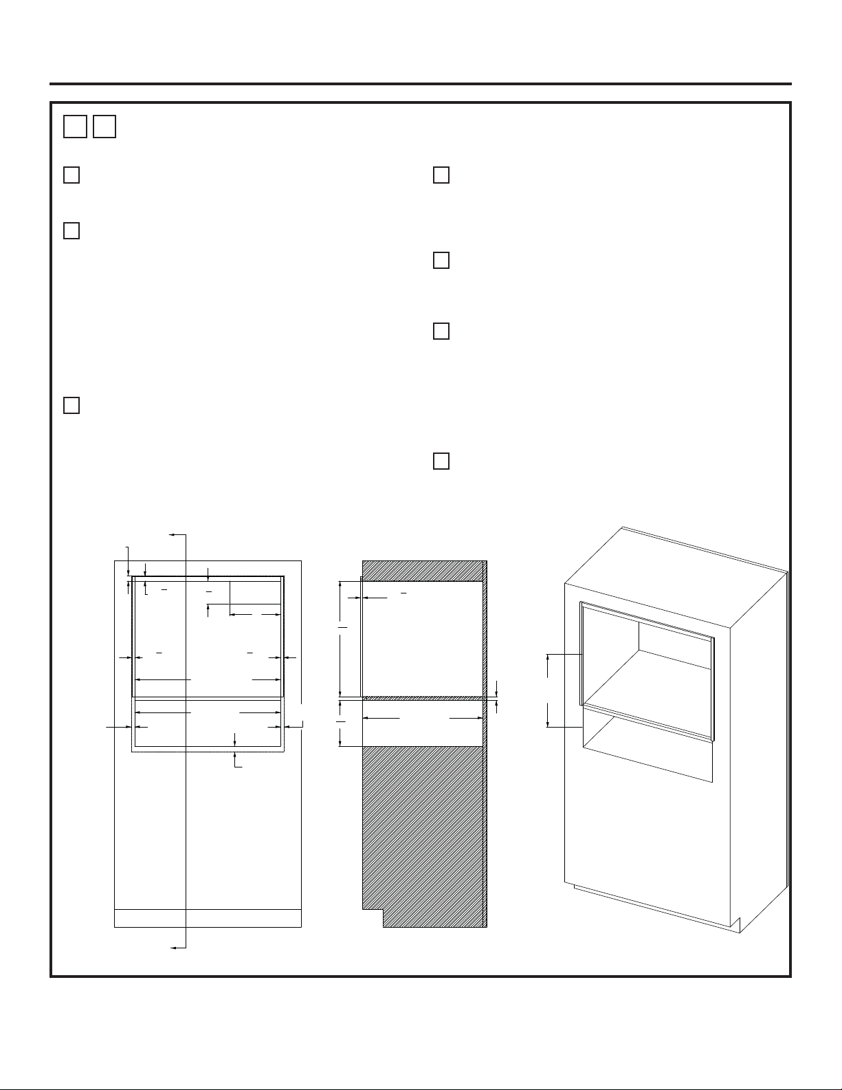
31-2001053 Rev. 0 19
1
M
HORNO DE HOGAR SOBRE CAJÓN PARA CALENTAR – INSTALACIÓN
ESTÁNDAR CON ESPACIO LIBRE INTERMEDIO MÍNIMO
A
45” es la altura de instalación mínima requerida. El
horno podrá ser instalado más arriba, dependiendo de la
preferencia del propietario.
B
La Plataforma del Horno de Hogar deberá poder soportar
200 libras (91 kg.). Para esta instalación, se recomienda
enfáticamente bloquear la plataforma dentro de las
paredes laterales, usando uniones de carpintería tipo
Dado. También se recomienda el uso de sujetadores
y pegamento para madera, a fin de reforzar aún más
las uniones de carpintería. La veta de la madera de la
plataforma se deberá orientar de izquierda a derecha.
El borde frontal de la plataforma deberá poseer una
superficie con acabado. Para consultar sobre conceptos
de uniones, lea las ilustraciones 1Q y 1R.
C
Se requiere un cerramiento sólido en las partes superior,
inferior, izquierda, derecha y trasera. La superficie trasera
podrá ser de yeso. Se recomienda el uso de técnicas
de fabricación y ensamble avanzadas, a fin de asegurar
un grado preciso de nivelación y paralelismo de los
gabinetes.
D
Ubicación de la caja de empalmes: Deberá estar nivelado
con la superficie trasera de modo que no se extienda
sobre la profundidad del gabinete de 23-1/2 pulgadas. La
caja de empalmes podrá estar ubicada en un gabinete
adyacente.
E
Se recomienda el uso de un perfil de 1/8” MÁS ALLÁ de
las dimensiones de SUPERPOSICIÓN, a fin de contar
con un espacio libre para el desplazamiento del cajón y la
puerta.
F
Se podrán agregar soportes exteriores sobre los laterales
y la parte superior de la abertura del Horno de Hogar,
a fin de poder alinear la superficie frontal del Horno
de Hogar con la superficie frontal del horno de pared
que se encuentra debajo. El acabado será acorde con
los requisitos del cliente. Un acabado negro liso podrá
combinar mejor con el aspecto lateral del horno que se
encuentra debajo.
G
La dimensión de la línea central de abertura se toma
sobre la ABERTURA FRONTAL de cada cerramiento.
Instalacións
ELEC
LEA LA NOTA D
PLATAFORMA DEL HORNO DE HOGAR
LEA LA NOTA B
SUPERPOSICIÓN
DE 1-1/16”
SUPERPOSICIÓN
DE 1-1/16”
SUPERPOSICIÓN
DE 11/16”
4
1
2
"
10"
7
8
"
LEA LA NOTA F
1
2
"
LEA LA NOTA F
1
2
"
LEA LA NOTA F
ANCHO DEL ESPACIO
LIBRE DE 28-1/2”
ANCHO DEL ESPACIO
LIBRE DE 28-1/2”
16 31/64"
C
L
A
C
L
LEA LA NOTA G
3
8
"
LEA LA NOTA F
22
9
16
"
8
31
32
"
PROFUNDIDAD
DEL GABINETE
DE 23-1/2”
MIN. DE 23/32”
“CONTRACHAPADO
DE 3/4”
SECCIÓN A-A
A
A
SUPERPOSICIÓN
DE 11/16”
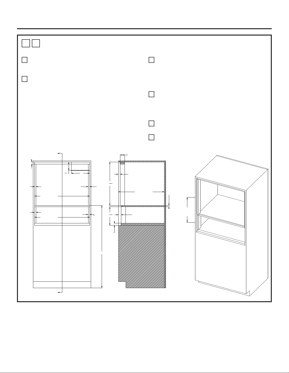
20 31-2001053 Rev. 0
1
N
HORNO DE HOGAR SOBRE CAJÓN PARA CALENTAR – INSTALACIÓN CON
MONTAJE AL RAS CON ESPACIO LIBRE INTERMEDIO MÍNIMO
A
45” es la altura de instalación mínima requerida. El
horno podrá ser instalado más arriba, dependiendo de la
preferencia del propietario.
B
La Plataforma del Horno de Hogar deberá poder soportar
200 libras (91 kg.). Para esta instalación, se recomienda
enfáticamente bloquear la plataforma dentro de las
paredes laterales, usando uniones de carpintería tipo
Dado. También se recomienda el uso de sujetadores
y pegamento para madera, a fin de reforzar aún más
las uniones de carpintería. La veta de la madera de la
plataforma se deberá orientar de izquierda a derecha.
El borde frontal de la plataforma deberá poseer una
superficie con acabado. Para consultar sobre conceptos
de uniones, lea las ilustraciones 1Q y 1R.
C
Se requiere un cerramiento sólido en las partes superior,
inferior, izquierda, derecha y trasera. La superficie trasera
podrá ser de yeso. Se recomienda el uso de técnicas
de fabricación y ensamble avanzadas, a fin de asegurar
un grado preciso de nivelación y paralelismo de los
gabinetes.
D
Ubicación de la caja de empalmes: Deberá estar nivelado
con la superficie trasera de modo que no se extienda
sobre la profundidad del gabinete de 24-15/16 pulgadas.
La caja de empalmes podrá estar ubicada en un gabinete
adyacente.
E
La base frontal de los soportes interiores deberán poseer
un acabado de su superficie.
F
La dimensión de la línea central de abertura se toma
sobre la ABERTURA FRONTAL de cada cerramiento.
Instalacións
ELEC.
LEA LA NOTA D
PLATAFORMA DEL HORNO DE HOGAR
LEA LA NOTA B
10"
4
1
2
"
SOPORTE
DE 1 1/8”
SOPORTE
DE 3/4”
SOPORTE
DE 3/4”
MÍN. DE 45”
ANCHO DEL ESPACIO
LIBRE DE 30”
ANCHO DEL ESPACIO
LIBRE DE 30”
SOPORTE
DE 3/4”
SOPORTE
DE 3/4”
MÍN. DE 17 39/64”
C
L
A
C
L
LEA LA NOTA F
PROFUNDIDAD DEL SOPORTE DE 2-1/2”
REVERSO DEL SOPORTE
DEL HORNO DE HOGAR DE 7/8”
23
11
16
"
SOPORTE
DE 1 1/8”
10
3
32
"
REVERSO DEL SOPORTE
DEL CAJÓN PARA CALENTAR
DE 1 3/8”
PROFUNDIDAD DEL GABINETE
DE 24 15/16”
MIN. DE 23/32”
“CONTRACHAPADO DE 3/4”
SECCIÓN A-A
A
A
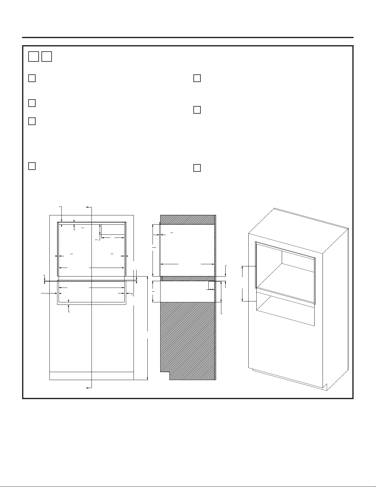
31-2001053 Rev. 0 21
1
O
HORNO DE HOGAR SOBRE CAJÓN PARA CALENTAR – INSTALACIÓN
ESTÁNDAR CON PLATAFORMA INTERMEDIA DE 2”
A
45” es la altura de instalación mínima requerida. El
horno podrá ser instalado más arriba, dependiendo de la
preferencia del propietario.
B
La Plataforma del Horno de Hogar deberá poder soportar
200 libras (91 kg.).
C
Se requiere un cerramiento sólido en las partes superior,
inferior, izquierda, derecha y trasera. La superficie trasera
podrá ser de yeso. Se recomienda el uso de técnicas
de fabricación y ensamble avanzadas, a fin de asegurar
un grado preciso de nivelación y paralelismo de los
gabinetes.
D
Ubicación de la caja de empalmes: Deberá estar nivelado
con la superficie trasera de modo que no se extienda
sobre la profundidad del gabinete de 23-1/2 pulgadas. La
caja de empalmes podrá estar ubicada en un gabinete
adyacente.
E
Se recomienda el uso de un perfil de 1/8” MÁS ALLÁ de
las dimensiones de SUPERPOSICIÓN, a fin de contar
con un espacio libre para el desplazamiento del cajón y la
puerta
F
Se podrán agregar soportes exteriores sobre los laterales
y la parte superior de la abertura del Horno de Hogar,
a fin de poder alinear la superficie frontal del Horno
de Hogar con la superficie frontal del horno de pared
que se encuentra debajo. El acabado será acorde con
los requisitos del cliente. Un acabado negro liso podrá
combinar mejor con el aspecto lateral del horno que se
encuentra debajo.
G
La dimensión de la línea central de abertura se toma
sobre la ABERTURA FRONTAL de cada cerramiento.
Instalacións
ELEC.
LEA LA NOTA D
PLATAFORMA DEL HORNO DE HOGAR
LEA LA NOTA B
4
1
2
"
10"
SUPERPOSICIÓN
DE 1 1/16”
SUPERPOSICIÓN
DE 11/16”
SUPERPOSICIÓN
DE 1 1/16”
7
8
"
LEA LA NOTA F
1
2
"
LEA LA NOTA F
1
2
"
LEA LA NOTA F
ANCHO DEL ESPACIO
LIBRE DE 28 1/2”
ANCHO DEL ESPACIO
LIBRE DE 28 1/2”
SOPORTE
DE 1/4”
2” ENTRE
ESPACIOS
LIBRES
PROFUNDIDAD
DEL SOPORTE
DE 2-1/2”
PROFUNDIDAD DE GABINETE
DE 23-1/2”
3
8
"
LEA LA NOTA F
22
9
16
"
9
1
4
"
SECCIÓN A-A
17 29/32"
C
L
A
C
L
LEA LA NOTA G
MÍN. DE 45”
A
A
PLATAFORMA
DE 9” HASTA
EL SOPORTE
ANTI-VOLCADURAS
SUPERPOSICIÓN
DE 5/16”
SUPERPOSICIÓN
DE 11/16”
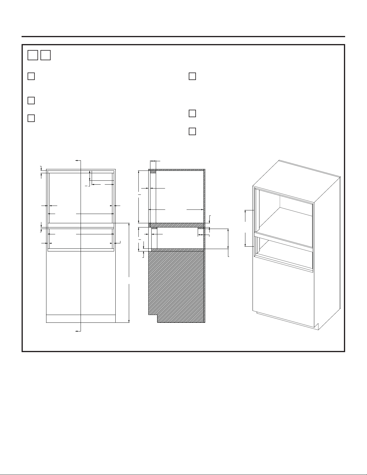
22 31-2001053 Rev. 0
1
P
HORNO DE HOGAR SOBRE CAJÓN PARA CALENTAR – INSTALACIÓN CON
MONTAJE AL RAS CON PLATAFORMA INTERMEDIA DE 2”
A
45” es la altura de instalación mínima requerida. El
horno podrá ser instalado más arriba, dependiendo de la
preferencia del propietario.
B
La Plataforma del Horno de Hogar deberá poder soportar
200 libras (91 kg.).
C
Se requiere un cerramiento sólido en las partes superior,
inferior, izquierda, derecha y trasera. La superficie trasera
podrá ser de yeso. Se recomienda el uso de técnicas
de fabricación y ensamble avanzadas, a fin de asegurar
un grado preciso de nivelación y paralelismo de los
gabinetes.
D
Ubicación de la caja de empalmes: Deberá estar nivelado
con la superficie trasera de modo que no se extienda
sobre la profundidad del gabinete de 24-15/16 pulgadas.
La caja de empalmes podrá estar ubicada en un gabinete
adyacente.
E
La base frontal de los soportes interiores deberán poseer
un acabado de su superficie.
F
La dimensión de la línea central de abertura se toma
sobre la ABERTURA FRONTAL de cada cerramiento.
Instalacións
ELEC.
LEA LA NOTA D
PLATAFORMA DEL HORNO DE HOGAR
LEA LA NOTA B
4
1
2
"
10"
SOPORTE
DE 1 1/8”
ANCHO DEL ESPACIO
LIBRE DE 30”
SOPORTE
DE 3/4”
SOPORTE
DE 3/4”
SOPORTE
DE 5/8”
SOPORTE
DE 3/4”
SOPORTE
DE 3/4”
ANCHO DEL ESPACIO
LIBRE DE 30”
MÍN. DE 45”
19 7/32"
C
L
A
C
L
LEA LA NOTA F
REVERSO DEL SOPORTE
DEL HORNO DE HOGAR DE 7/8”
PROFUNDIDAD
DEL GABINETE
DE 24 15/16”
REVERSO DEL SOPORTE
DEL CAJÓN PARA CALENTAR
DE 1 3/8”
PROFUNDIDAD DEL SOPORTE DE 2-1/2”
23
11
16
"
PROFUNDIDAD
DEL SOPORTE
DE 2 ½”
10
3
4
"
SOPORTE
DE 1 1/8”
2” ENTRE
ESPACIOS LIBRES
SECCIÓN A-A
A
A
PLATAFORMA
DE 9” HASTA
EL SOPORTE
ANTI-VOLCADURAS
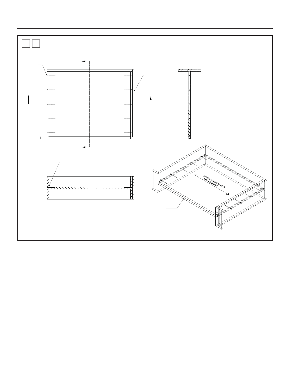
31-2001053 Rev. 0 23
1
Q
PLATAFORMA DE HORNO DE HOGAR PARA UN ESPACIO LIBRE MÍNIMO ENTRE
ELECTRODOMÉSTICOS: CONCEPTO DADO Y SUJETADOR MECÁNICO
Instalacións
Borde Estético
Panel Estético
para Cubrir las Uniones
de la Pared Expuesta
Sujetadores
Mecánicos
AA
B
B
SECCIÓN A-A
Uniones DADO y Pegamento para Madera
SECCIÓN B-B
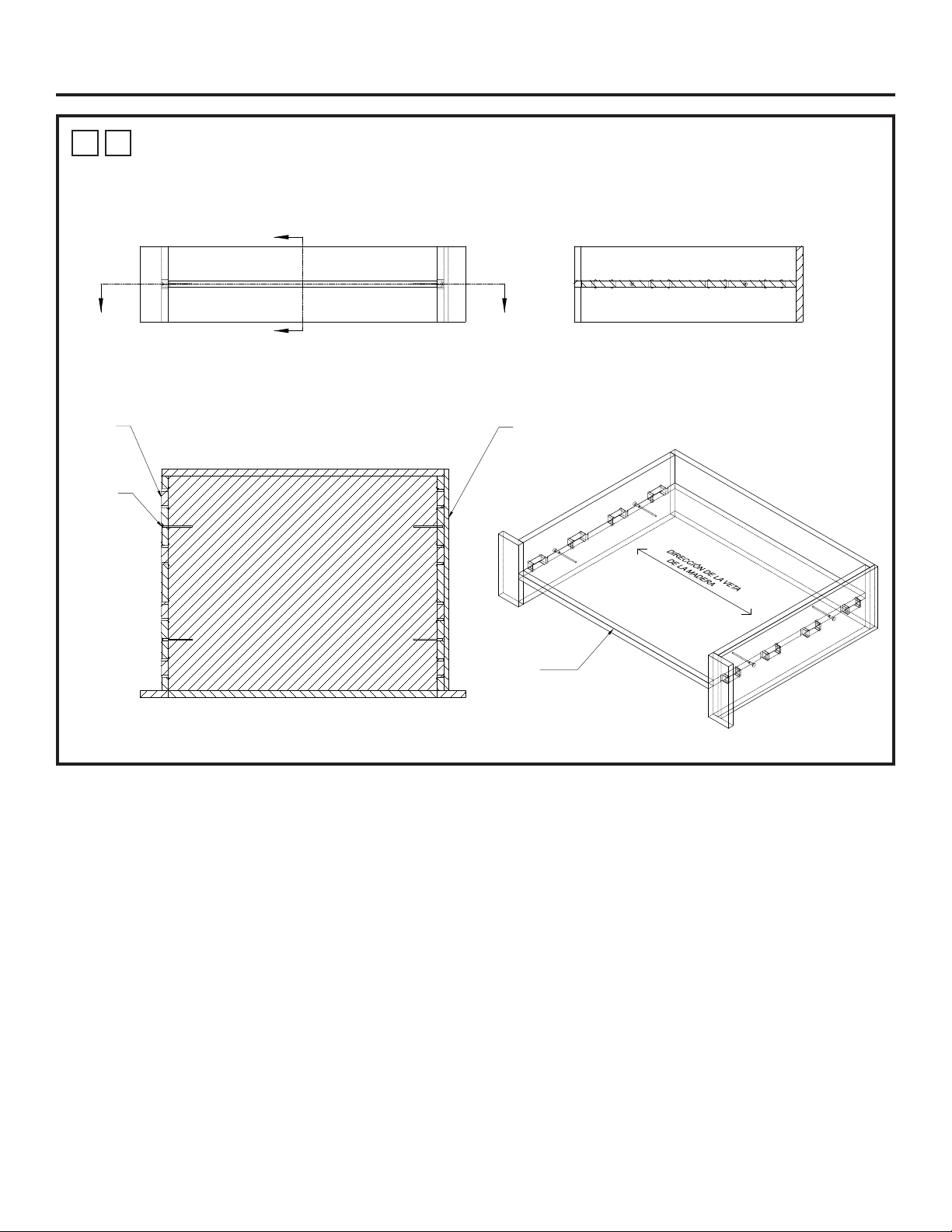
24 31-2001053 Rev. 0
1
R
PLATAFORMA DE HORNO DE HOGAR PARA UN ESPACIO LIBRE MÍNIMO
ENTRE ELECTRODOMÉSTICOS: CONCEPTO DE ESPIGA Y SUJETADOR
MECÁNICO
Instalacións
Borde Estético
AA
B
B
SECCIÓN A-A
Panel Estético
para Cubrir las Uniones
de la Pared Expuesta
Uniones
de Espiga
Sujetadores
Mecánicos
SECCIÓN B-B
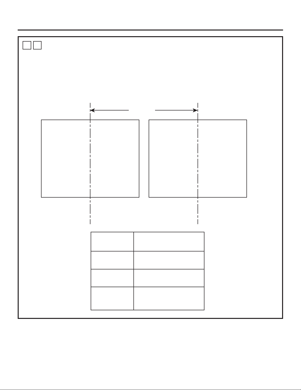
31-2001053 Rev. 0 25
Instalacións
1
S
INSTALACIÓN DEL COMBO DE LADO A LADO
Para acceder a un listado de productos compatibles con la Instalación del Horno de Lado a Lado, consulte a través de Internet
en geappliances.com/combinations.
Por favor, consulte las instrucciones de instalación de ambas unidades para sus respectivas instalaciones.
Para solicitar asistencia en relación al diseño del gabinete, por favor conéctese con un Diseñador de Monogram.
Dimensión A
Horno de Hogar
Para conocer las
Dimensiones de los
Espacios Libres,
consulte 1A o 1B.
Para conocer
las Dimensiones
de los Espacios
Libres, consulte
las Instrucciones
de Instalación
del Producto
Específico.
Tipo de Horno
Distancia Mín. – Líneas
Centrales de Producto a
Producto de la Dimensión A
Horno de Hogar
junto al Horno de
Pared
30.5”
Horno de Hogar
junto al Horno de
Vapor
30.5”
Horno de Hogar
junto al Horno de
Pared con Puerta
Francesa
42.5”
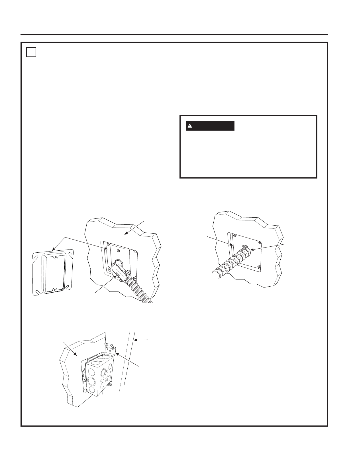
26 31-2001053 Rev. 0
Instalación
2
CONEXIONES ELÉCTRICAS
ATENCIÓN AL INSTALADOR
Todos los hornos eléctricos de pared deben ser
cableados directamente en una caja de conexión.
Un “enchufe-receptáculo” NO ES permitido en estos
productos.
NO acorte el conducto flexible. La abrazadera para
controlar la presión debe estar firmemente adherida a
la caja de conexión y el conductor flexible debe estar
firmemente adherido a la abrazadera. Si el conducto
flexible no se ajusta al interior de la abrazadera, no instale
el horno hasta que obtenga el tamaño apropiado.
Nota al electricista: Los 3 alambres eléctricos
proporcionados con este aparato son reconocidos por
la UL para conexiones a cableado residencial de mayor
calibre. El aislante de estos 3 alambres supera las
especificaciones de temperatura indicadas para cableado
residencial. La capacidad actual de conducción del cable
depende del calibre del cableado y de la clasificación de
la temperatura del aislamiento alrededor del alambre.
ADVERTENCIA
Una conexión inapropiada
del cableado de aluminio residencial
con cobre, podría resultar en un peligro
eléctrico o hasta en incendio. Use solamente
conectores diseñados para unir cobre con
aluminio y siga las recomendaciones del
fabricante con mucho cuidado.
OPCIONES DE INSTALACIÓN RECOMENDADAS
Opción 1 - Una caja de empalmes con un anillo de yeso y un
amortiguador de refuerzo a 90°, sobre un montante detrás de
la pared de yeso.
Opción 2 - Caja de empalmes estándar con un amortiguador
de refuerzo recto, montado sobre una viga detrás del panel
de yeso.
Anillo de Yeso
Frente de la
Pared de Yeso
VISTA FRONTAL
Amortiguador de
Refuerzo a 90°
Montante
VISTA TRASERA
Parte Trasera de
la Pared de Yeso
Caja de
Empalmes
Montada
Amortiguador de
Refuerzo Recto
Caja de
Empalmes
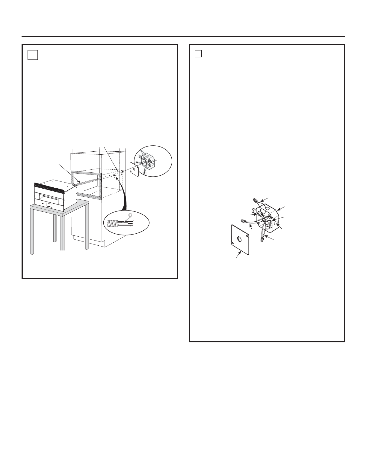
31-2001053 Rev. 0 27
Instalación
A
CONEXIÓN PARA NUEVA CONSTRUCCIÓN
Y DE CIRCUITO DE EMPALMES DE CUATRO
CONDUCTORES
• Cuando se instale en una construcción nueva, o
• Cuando se instale en una casa móvil, o
• Al instalar en un vehículo de recreación, o
• Cuando los códigos locales no permitan hacer conexión
a tierra a través de un cable neutro:
NOTA: Si los cables del hogar poseen conductores de
aluminio, ver la ADVERTENCIA en la página 5.
Cuando conecte un circuito derivado de cuatro
conductores, si lo permiten los códigos locales:
1. Conecte el conductor de conexión a tierra junto con el
cable neutro (blanco) al neutro del circuito de empalmes
(de color blanco o gris), usando una tuerca para cables.
2. Conecte el cable a tierra del artefacto (verde o cobre) de
acuerdo con los códigos locales.
3. Conecte el cable neutral (blanco) del horno con el neutral
de circuito derivado (blanco o gris) de acuerdo con
códigos locales, utilizando un tapón de alambre.
4. Conecte el cable rojo del horno al cable rojo del circuito
derivado y el cable negro del horno al cable negro del
circuito derivado de acuerdo con los códigos locales,
utilizando tapones de alambre.
5. Instale una abrazadera adecuada de alivio de tensión.
6. Instale la tapa de la caja de conexiones.
Tapa de la caja de conexiones
Blanco
Negro
Rojo
Circuito ramificado
Cables a
tierra
Agujero ciego
alternativo
El tubo de la
estufa se ajusta
en la caja
2
CONEXIONES ELÉCTRICAS (Cont)
1. Desconecte el interruptor del circuito o retire los fusibles
que alimentan el circuito de empalmes del horno.
2. Con el horno enfrente de la abertura del gabinete, sobre
una mesa o plataforma conecte el conducto flexible a la
caja de conexión como se muestra en la figura. Coloque
el conducto de manera que quede apoyado sobre la
parte superior del horno en forma de bucle natural
cuando se instale el horno. Usted necesitará comprar
una abrazadera liberadora de presión para completar la
conexión del conducto hacia la caja de conexión.
La abrazadera liberadora
de presión (no incluida)
debe usarse en la caja
de conexión
Coloque el horno en el
soporte para ayudar en la
conexión del conductor, debe
soportar 200 libras (91kg).
Ubicación de la caja de conexión
Conducto
ALAMBRES DE
CONEXIÓN A
TIERRA
TIERRA
ROJO
BLANCO
NEGRO

28 31-2001053 Rev. 0
Instalación
2
CONEXIONES ELÉCTRICAS (Cont)
B
CONEXIÓN DE CIRCUITO DE EMPALMES DE
TRES CONDUCTORES
NOTA: Si los cables domésticos son conductores de
aluminio, ver la ADVERTENCIA en la página 5.
Cuando conecte un circuito derivado de tres
conductores, si lo permiten los códigos locales:
1. Evite que el conductor neutro (blanco) quede
enredado con cualquier otro cable. De ser
necesario, corte el conductor neutro (blanco) y
luego vuelva a pelar el mismo, a fin de exponer la
longitud adecuada del conductor.
2. Conecte el cable rojo del horno al cable rojo del
circuito derivado y el cable negro del horno al cable
negro del circuito derivado de acuerdo con los
códigos locales, utilizando tapones de alambre.
3. Instale una abrazadera adecuada de alivio de tensión.
4. Instale la tapa de la caja de conexiones.
Cables a tierra
y neutrales (blanco)
Encinte o Prense
Cable neutral
conexión
Negro
Rojo
Circuito ramificado
Agujero ciego
alternativo
El tubo de la
estufa se ajusta
en la caja
Tapa de la caja de conexiones
3
INSTALACIÓN DEL HORNO
EN EL GABINETE
2. Eleve el horno hasta el espacio del gabinete usando
la parte inferior como agarre. No lo levante desde la
abertura del horno.
3. Con cuidado, deslice la parte trasera del horno dentro del
espacio hasta que la rejilla superior toque apenas la cara
frontal del gabinete. NOTA: No empuje con demasiada
fuerza, ya que se podrán producir daños sobre la rejilla
superior.
4. Haga agujeros piloto sobre el gabinete para el montaje
de la rejilla superior, usando una broca de 3/32” y el
agujero del marco como guía. Instale los dos tornillos
Phillips de 3/4”.
5. Una vez que el horno se encuentre instalado en el
gabinete, alinee el Marco de Ventilación Inferior con
los agujeros de los soportes de montaje y realice su
instalación usando dos tornillos Torx de 1/2”.
3
INSTALACIÓN DEL HORNO
EN EL GABINETE
B
CON KIT DE MARCOS
1. Antes de levantar el horno sobre el espacio del gabinete,
retire los seis tornillos de la ventilación superior y adhiera
la rejilla superior a la parte superior del horno usando los
mismos tornillos, como se muestra.
Tornillos
45°

31-2001053 Rev. 0 29
Instalación
LISTA DE CONTROL PARA LA OPERACIÓN
IMPORTANTE
• Retire cualquier artículo del interior del horno.
• Cerciórese de que el conducto está conectado firmemente a
la caja de conexión eléctrica.
• Conecte la energía hacia el horno. (Consulte su Manual del
propietario.) Verifique que todas las funciones de cocción
operen correctamente.
• Cerciórese de que el interruptor de circuito no se haya
disparado o de que los fusibles de la casa no estén
quemados.
• Consulte el manual del propietario para una lista de
problemas eventuales.
NOTA AL ELECTRICISTA: los alambres eléctricos
proporcionados con este aparato son reconocidos por
la UL para las conexiones con cableado residencial de
mayor calibre. El aislante de estos alambres supera las
especificaciones indicadas para cableado residencial. La
capacidad actual de conducción del cable depende de la
clasificación de la temperatura del aislamiento alrededor
del alambre.
NOTA: Cableado de aluminio
A.
WARNING
UNA CONEXIÓN INAPROPIADA DEL
CABLEADO DEL ALUMINIO RESIDENCIAL CON EL
COBRE, PODRÍA RESULTAR EN PROBLEMAS SERIOS
O EN INCENDIO.
B. Conecte los alambres de cobre a los alambres de
aluminio usando conectores especiales diseñados y
aprobados por UL para unir cobre y aluminio y siga
cuidadosamente el procedimiento para hacer las
conexiones recomendadas por el fabricante.
NOTA: El alambrado que se use, la ubicación y el
tipo de conexión, etc., deben cumplir con las buenas
prácticas de alambrado y los códigos locales.
LISTA DE CONTROL ANTES DE LA PRUEBA
De estar presente, retire toda la película protectora.
Revise para asegurarse de que todos los alambres estén
bien conectados y no aplastados.
Retire los soportes de embalaje de la superficie de cocción:
1. Retire la Varilla del Soporte del Embalaje empujando
hacia arriba sobre un extremo.
2. Retire ambos Pies del Soporte de Embalaje, deslizando
estos hacia afuera de la pared y hacia el centro de la
Piedra.
3. Realice su retiro del horno y descártelos.
Varilla del Soporte del Embalaje
Pies del
Soporte del
Embalaje

NOTA: Al realizar las instalaciones descriptas en este libro,
se deberán usar anteojos o gafas de seguridad.
NOTA: Monogram Appliances se esfuerza de forma
constante para mejorar sus productos. Por lo tanto, los
materiales, el aspecto y las especificaciones están sujetos a
cambios sin aviso previo
Impreso en Estados Unidos
31-2001053 Rev. 0
01-22 GEA