
OPERATOR'S MANUAL
ICRRFTSMRN" I
PRO FES S i O NAL
12 in. COMPOUND MITER SAW
DOUBLE INSULATED
Model No.
315.212350
_k WARNING: To reducethe riskof injury,
the usermust read and understand the
operator'smanual beforeusingthis product.
Customer Help Line: 1-800-932-3188
Bears, Roebuck and Co., 3333 Beverly Rd., Hoffman Estates, IL 60179 USA
Visit the Craftsman web page: www.sears.corn/craftsman
983000-550 Save this manual for future reference
9-04
• Warranty............................................................................................................................................................................ 2
m Introduction....................................................................................................................................................................... 2
• GeneralSafety Rules..................................................................................................................................................... 3-4
• SpecificSafety Rules..................................................................................................................................................... 4-5
• Symbols......................................................................................................................................................................... 6-7
• Electrical............................................................................................................................................................................ 8
mmGlossaryofTerms.............................................................................................................................................................. 9
m Fsatures..................................................................................................................................................................... 10-12
mmToolsNeeded ................................................................................................................................................................. 12
mmLooseParts................... ¢_I ............................................................................................................................................... 13
• Assembly................................................................................................................................................................... 14-23
• Operation................................................................................................................................................................... 23-31
• Adjustments................................................................................................................................................................... 32
• Maintenance.............................................................................................................................................................. 33-35
• ExplodedView........................................................................................................................................................... 37-45
• PartsOrdering/Service ...................................................................................................................................... BackPage
ONE YEAR FULL WARRANTY ON CRAFTSMAN TOOL
IfthisCraftsman tool fails due to a defect in materialor workmanshipwithinone year from the date of purchase,
CONTACT THE NEAREST OEARS PARTS & REPAIR CENTER at 1-800.-4-MY-HOME_ and Searswi(fmpafr it, free of
charge.Thiswarrantyapplies onlywhilethis productis In the UnitedStates.
Itthistool isused for commercialor rentalpurposes,thiswarrantywillapplyfor onlyninety daysfrom the dateof
pumhasa.
ThLswarrantygives you specificlegaldghte,and you may also haveotherdghtewhichvaryfrom stateto state.
Seam, Roebuck and Co., Dept. S17WA, Hoffman Estates, IL 60179
Thistool has manyfeaturesfor makingitsuse more pleasantand enjoyable.Safety,performance,and dependability
havebeen giventop pr_orLtyinthe designof this productmaking It easyto maln_ln and operate.
A WARNING: Road and understand all Ir_struc-
tlons. Failuretofollow all fnstructions listedbelow,
may resultin eiectdc shock,fireand/or serious
personal injury,
READ ALL INSTRUCTIONS
• KNOW YOUR POWER TOOL. Read the operator's
manualcarefully.Learnthe saw's applicationsand
limitationsas well as the specificpotentialhazards
retatedto this tool
• GUARD AGAINST ELECTRICAL SHOCK BY PRE-
VENTING BODY CONTACT WITH GROUNDED
SURFACES. Forexample, pipes, radiators,ranges,
refrigeratorenclosures,
• KEEP GUARDS IN PLACE and ingood workingorder.
• REMOVE ADJUSTING KEYS AND WRENCHES.
Formhabit of checkingto see thatkeys and adjusting
wrenchesareremoved fromtoo] beforeturningit on.
• KEEP WORK AREA CLEAN. Clutteredareasand
benchesInviteaccidents. DO NOT leavetoolsor
pieces ofwood on the saw while itisin operation.
= DO NOT USE IN DANGEROUS ENVIRONMENTS,
Do not usapower toolsin damp orwet Iocetions or
exposeto rain.Keep the work areawell 1il.
• KEEP CHILDREN AND VISITORS AWAY.Allvisitors
shouldwear safety glassesand be kept a safe
distancefrom work area. 0o not letvisitors contacttool
or extensioncordwhile operating.
• MAKE WORKSHOP CHILDPROOFwith padlocks and
masterswitches,or by removingstarterkeys.
• DON'T FORCE TOOL. It,w[ll do theJobbetter and
saferat the feed rate for which"_was designed,
• USE RIGHT TOOL. Don'tforce thetool or attachment
to do a Jobit was notdesignedfor.Don't useItfor a
purposenotintended.
• USE THE PROPER EXTENSION CORD. Make sure
your extensioncordIs in good condftlon.Usa onlya
cordheavy enoughto carry the currentyourproduct
wittdraw.An undersizedcordwltl causea dropin line
voltageresultingin lossof power and overheating.A
wire gauge size(A.W.G.)ofat least14 isrecommended
for an extensioncord25 feet or less In length.If]n
doubt, usethe nextheaviergauge, The smallerthe
gauge number, the heavierthe cord.
• DRESS PROPERLY. Do notwear loose clothing,
groves,neckties,orjewelry.They can getcaught
and draw you intomoving parts.Rubberglovesand
nonskidfootwearare recommendedwhen working
outdoors.Alsowear protective haircoveringto con_in
longhair.
• ALWAYS WEAR SAFETY GLASSES WITH SIDE
SHIELDS. Everydayeyeglasseshaveonlyimpact-
resistanttenses,they are NOT safetyglasses.
• SECURE WORK. Use clampsora viseto holdwork
when practical it's saferthanuslngyourhandand
frees both handsto operatetool.
• DON'T OVERREACH. Keepproperfooting and
balanceat all times.
• MAINTAIN TOOLS WITH CARE. Keep toolssharp
and cleanfor betterand safer performance.Follow
Instructionsfor lubricatingand changingaccessories.
• DISCONNECT TOOLS. When not in use,before
servicing,or when changingattachments,blades, bits,
cutters,etc., alltoolsshouldbe disconnected.
• AVOID ACCIDENTAL STARTING. Be sure swItch]Soff
when pluggingin anytool.
• USE RECOMMENDED ACCESSORIES. The useof
improperaccessories may riskinjury.
• NEVER STAND ON TOOL. Seriousinjurycouldoccur
ifthetool is tipped or If the cuttingtool isunintention-
ally contacted.
• CHECK DAMAGED PARTS. Beforefurtheruse of
the tool,a guardor otherpart that is damagedshould
be carefullychecked todeterminethat itwilloperate
propedyand performits intendedfunction. Check for
alignment ofmovingparts,binding of movingparts,
breakageof parts,mounting and any otherconditions
that mayaffect _s operation. A guard or otherpart that
is damagedmust be properlyrepairedor replacadby
an authorizedservice centerto avoidriskof personal
Injury.
• USE THE RIGHT DIRECTION OF FEED. Feed work
intoa bladeor cutter against thedirectionofrotationof
blade or cutteronly,
• NEVER LEAVE TOOL RUNNING UNATrENDED.
TURN THE POWER OFF.Don't leavetooluntil it
comesto a compfefestop.
• PROTECT YOUR LUNGS. Wear a face or dust mask if
the cuttingoperation isdusty.
• PROTECT YOUR HEARING.Wear hearingprotection
dudng extended pededsof operation.
• DO NOT ABUSE CORD. Never yankcard to discon-
nectfrom receptacle,Keep cordfrom heat, oil and
sharpedges.
• USE OUTDOOR EXTENSION CORDS. Whentool is
used outdoors,usa onlyextension cordswith ap-
provedgroundconnectionthatare intendedfor use
outdoorsand so marked.
• KEEP BLADES CLEAN, SHARP, AND WITH SUF-
RCIENT SET. Sharp blades minimize stalling and
kickback.
• BLADE COASTS AFTER BEING TURNED OFR
• NEVER USE IN AN EXPLOSIVE ATMOSPHERE.
Nom_I sparkingofthe motor could ignitefumes.

• INSPECT TOOL CORDS PERIODICALLY. If damaged,
haverepairedby a qualifiedservice technicianat
an authorizedservicefacility,The conductorwith
insulationhavingan outersurfacethat isgreenwith
orw_thou_yellows_pes Is 1heequipment-gTound-
ingconductor.If repairor replacementofthe electric
cordor plug tsnecessary,do no'_connectthe equip-
men_-grounding conductorto a liveterminal.Repair
or replacea damagedorwom cordimmediately. Stay
constantly aware ol cord location and keepitwall away
fromthe rotatingblade.
• INSPECT EX'FENSIONCORDS PERIODICALLY and
replaceIfdamaged.
• POLARIZED PLUGS. Toreducethe riskof electric
shock,thistool hasa polar'lzedplug (one blade is
wider than the other).This plug willfitin a polarized
outletonlyoneway. if the plug does notf_tfullyinthe
outlet, revemethe plug. If_tstilldoesnot fit, contact a
qualifiedelectriciantoInstantt'neproperoutlet. Do not
changethe p_Jgin anyway.
• KEEP TOOL DRY,CLEAN, AND FREE FROM OIL
AND GREASE. Alwaysusa a ck_n c4olhwhen clean-
Ing.Never use brake fluids,gasoline,petroleum-based
products,or any solventsto clean tool.
• STAY ALERT AND EXERCISE CONTROL. Watch
what you aredoingand _se common sense. Do not
operate"_octwhen you aretired. DOnot rosh.
• DO NOT USE TOOL IF SWITCH DOES NOT TURN IT
ON AND OFF.Have defective switchesreplacedby an
authorizedservicecenter.
• USE ONLY CORRECT BLADES. Do not use blades
with Incorrect size holes.Never usebladewashers or
bladeboltsthat aredefectiveor incorrect.The maxi-
mum bladecapacity ofyoursaw is 12 in. (305 ram).
• BEFORE MAKING A CUT, BESURE ALL ADJUST-
MENTS ARE SECURE.
• BE SURE BLADE PATHIS FREE OF NAILS. (nspect
for and removeall nailsfrom lumberbeforecutting.
• NEVER TOUCH BLADE orothermoving parts during
USe.
• NEVER START A TOOLWHEN ANY ROTATING COM-
PONENrT IS IN CONTACT WITH THE WORKPIECE.
• DO NOT OPERATE A TOOL WHILE UNOER THE
INFLUENCE OF DRUGS, ALCOHOL, OR ANY
MEDICATION.
• WHEN SERVICING use only identir._l replacement
parts. Use of any other parts may create a hazard or
_use product damage.
• USE ONLY RECOMMENDED ACCESSORIES listed
in this manuel or sddendums, Use of accessories
that are not listed may cause the risk of personal
injury. Instructions for sate use of accessories are
included with the accessory,
• DOUBLE CHECK ALL SETUPS. Make sure blade is
tight and not making contact with saw or workplace
before connecting to power supply.
• FIRMLY CLAMP OR BOLTyour mitersaw to a work-
bench ortable at approximatelyhipheight.
• KEEP HANDS AWAY FROM CUTTING AREA. Do not
reachunderneathwork or Inblade cuttingpathwith
yourhandsend fingersfor any reason.Alwaysturnthe
poweroff.
• ALWAYS SUPPORT LONG WORKPIECES whilecut-
ting to minimizeriskof blade pinchingand kickback.
Saw may slip.walk or slldewhilecuttlnglong orheavy
boards.
• ALWAYS USE A CLAMP to securetheworkpioce
when possible.
• BE SURE THE BLADE CLEARS THE WORK,PIECE.
Never start the sew with the bladetouchingthe
workplace.A,ow motor_ come up tofullspeed
beforestartingcut.
• MAKE SURE THE MITER TABLE AND SAW ARM
(BEVEL FUNCTION) ARE LOCKED IN POSITION
BEFORE OPERATING YOUR SAW. Lock the miter
table by securely tightening the miter lock levers, Lock
the saw arm (beve_function) by securely tightening the
bevel lock knob.
NEVER USE A LENGTH STOP ON THE FREE SCRAP
END OF A CLAMPED WORKPIECE. NEVER hold
onto or bind the free scrap end of the workpiece in any
operalion. If awork clamp and length stop are used
together, they must both be instal_edon the same side
ofthe saw 1able to prevent the saw from catching the
loose end and kickJng up,
NEVER cut more than one piece at a time. DO NOT
STACK more than one workpiece on the saw table at a
tlme.
NEVER PERFORM ANY OPERATION FREEHAND,
Alwayspiece theworkpiece1obe cut on_hemiter
table and positioni_t'Lrmlyagainstthe fence as a bach-
stop.AJwaysusethe fence.

• NEVER handhold a workplace thatistoo small to be
clamped. Keep hands clear ofthe cuttingarea.
• NEVER reachbehind, under,orwithin threeinches
of the blade and its cuttingp_th with your handsand
fingersfor anyreason.
• NEVER reachto pick up a workpisce, a piece ofscrap,
or anythingelsethat istnor near the cuttingpathof the
blade.
• AVOID AWKWARD OPERATIONS AND HAND
POSITIONS where a suddenslipcould causeyour
handto move Intothe blade. ALWAYSmake sureyou
havegood balance. NEVER operate yourmitersaw
on the flooror in a crouchedposition.
• NEVER stand or haveany part ofyour bodyin linewith
the path ofthe saw blade.
• ALWAYSreleasethe power switch and allowthe
saw blade to stop rotatingbefore raisingitout ofthe
workpieca.
• DO NOT TURN THE MOTOR SWITCH ON AND OFF
RAPIDLY.This could causethe saw blade to loosen
and couldcreate a hazard.Shouldthis everoccur,
stand clear and allowthe saw blade to come toa
completestop,Disconnectyour saw fromthe power
supplyand securelyretightantheblade bo_t,
• IF ANY PART OF THIS MITER SAW IS MISSING or
shouldbreak, bend, or fail inanyway, or shouldany
aisctricalcomponent fadto perform property,shutoff
the power switch,removethe miter saw plugfrom the
powersourceand have damaged, missing, or failed
parts replacedbefore resumingoperation.
• ALWAYSSTAY ALERT[ Do notallowfamiliarity(gained
fromfrequent useofyoursaw)to causea careless
mistake. ALWAYS REMEMBER thata carelessfraction
of a second issufficienl lo inflictsevereinjury.
• MAKE SURE THE WORK AREA HAS AMPLE LIGHT-
ING to see the work and that no obstructionswillinter-
fere with safeoperationBEFORE perforn_ngany work
usingyoursaw.
• ALWAYSTURN OFF THE SAW beforedisconnecting
itto avoidaccidentalstartingwhen reconnectingto
powersup]_ly.NEVER lesve thesaw unattendedwhiis
connected to a power scurce.
• THIS TOOL shouldhavethe followingmarkings:
a) Weareye protection.
b) Keep hands out of pathof saw blade
c) Do not operatesaw withoutguardsin place.
d) Do not performanyoperationfreehand.
e) Never reacharoundsaw blade.
0 Turn offtooland waitfor saw bladeto stop before
movingworkpieca or changingsettings.
g) Disconnectpower(o_unplug toolas applicabis)
before changingbladeor servicing.
h,_ No loadspeed.
• ALWAYS carry the tool onlyby the carryinghandle.
• AVOID directeye exposurewhen usingthe laserguide.
• SAVETHEBE INSTRUCTIONS. Referto them
frequently and useto instructotherusers,if you loan
someone thistool, loan them theseinstructionsalso.
WARNING: Somedust created by powersanding, saw(r_j, grinding, drilli_j, and otherconstructionactivities
containschemicalsknownto cause cancer,birthdefectsor otherreproductiveharm. Someexamplesofthese
chemrcalsare:
• lead from leed-besed paints,
• crystallinesilicafrom bricksand cementand othermasonryproducts,and
• arsenicand chromiumfrom chemically-treatedlumber.
Yourriskfrom theseexposuresvades, dependin_on how often you do thistype ofwork.To reduceyourexposure
to these chemicals:work ina well ventilatedarea, and work with approved safety equipment,suchas thosedust
masksthat arespecially designedtofilter out microscopicparticles.
5

Someofthefollowing symbolsmay beused on thistool. Pleasestudythem and learntheirmeaning, Proper
interpretationofthese symbolswillallowyou tooperatethe tool betterand safer,
SYMBOL NAME DESIGNATION/EXPLANATION
V Volts Voltage
A Amperes C_rrest
Hz Hertz Frequency(cyclesper second)
W Watt Power
mln MinUtes Time
Altemat_ogCurrent Type of current
-.--- DirectCurrent Typeor a characteristicofcurrent
no NOLoadSpeed Rotationalspeed,at no load
[] Class IJConstruction Double-Insulatedconstruction
.../rain Per Minute Revolutions,strokes,surfacespeed,orbitsetc., per minute
Wet Conditions/_erf DOnot exposeto rainor useIn damp locations.
Read The Operator'sManual To reducethe dskof Injury,usermustread and understand
operator'smanual beforeusingthis product.
O Alwayswear safety gogglesor safety glasseswith sideEyeProtection shieldsanda full face shieldwhen operatingthis product.
Alert Precautionsthat invo}ve
Safety
your
Safety.
I
Failureto keepyourhands away from the blade willresult in
_o Hands Syrnbo! sedouspersonalInjury,
Failureto keep yourhandsaway fromthe bib,dewillresultinNo Hands Symbol eadous personalInjury.
No HandsSymbol Failureto keepyour handsaway fromthe bladewiltresult In
seriouspersonalinjury.
No Hands Symbol Failureto keep yourhands away from thebladswillresu(tin
seriouspersonal_njury,
(_ Hot Surface Toreducethe dsk of Inlury or d_m_e, svold contactwith
anyhot surface,
6
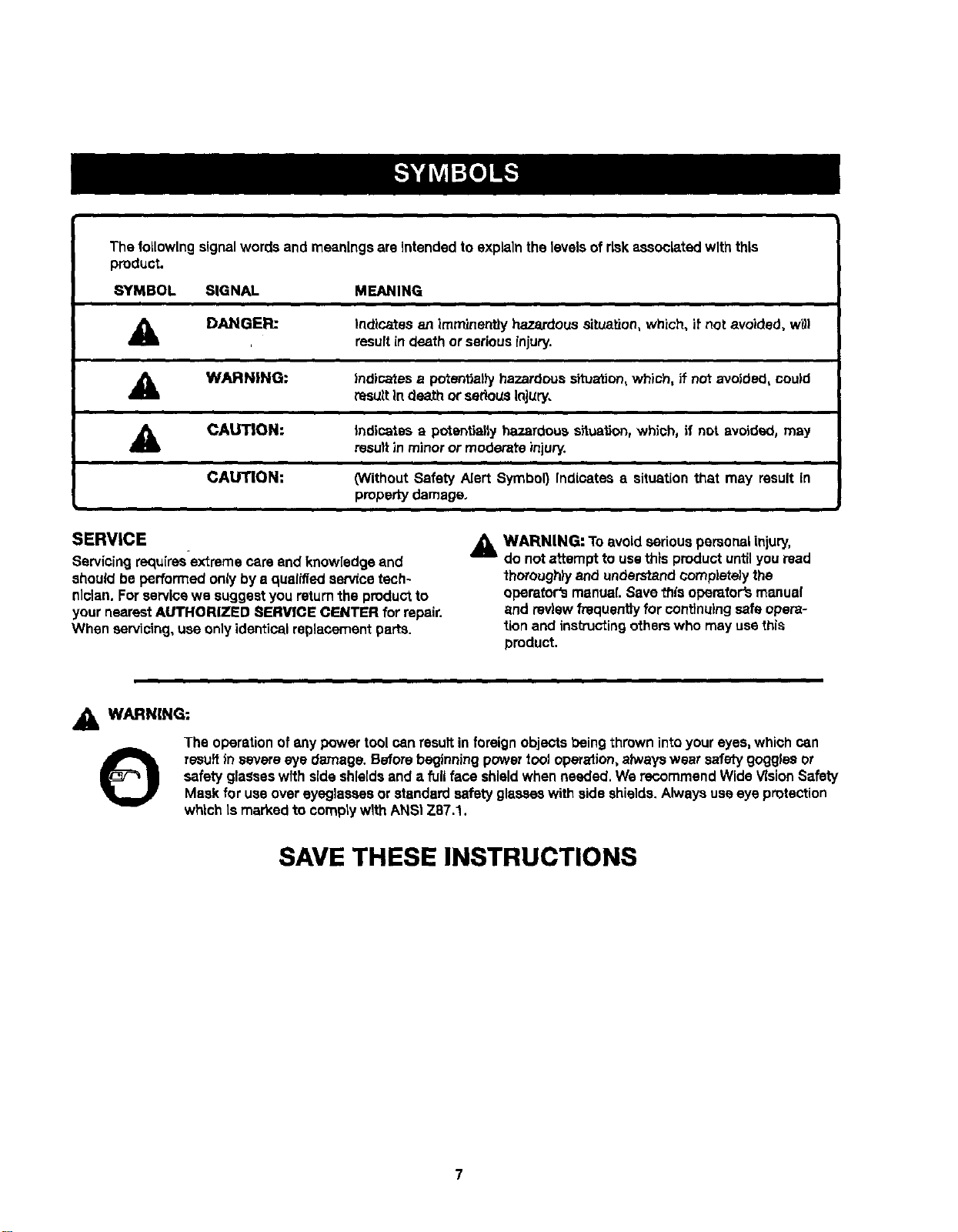
Thefollowingsignalwordsandmeaningsare intendedto explainthelevelsof risk associated with this
product.
SYMBOL SIGNAL MEANING
DANGER:
Indicatss an imminentlyhazardoussituation, Which,if not avoided, w_l
resultin death or seriousinjury.
A WARNING:
Indicatesa potentiallyhazardouss_uation, which, if not avoided, could
resultIndeath or seriousInjury.
A
CAUTION:
CAUTION:
i
Indicates a potentially hazardoussituation,which, if not avoided, may
resultin minoror moderate injury.
(WithoutSafety Alert Symbol) Indicates a situation that may result in
propertydamage.
SERVICE
Servicingrequ[rss-extreme care end knowledgeand
shouldbe performedonlybya qualifiedservice tech-
nician.Forservicewe suggestyou returnthe productto
yournearestAUTHORIZED SERVICE CENTER for repair.
When servicing,use onlyidenticalreplacementparts.
A WARNING: Toavoid seriouspersonalinjury,
do notattempt to usethis productuntilyou read
thorough_/and understandcompletelythe
operator'smanual. Savethis operator'smanua!
and review frequentlyfor continuingsafeopers-
tion and instructingotherswho may usethis
product.
A WARNING:
The operationofany powertool canresultin foreignobjectsbeingthrownintoyour eyes,whichcan
O resultin severeeye damage. Beforebeginningpower tooJoperalion,alwayswear safetygogglesor
safety glasseswfthside shieldsand a full face shieldwhen needed. We recommendWideVisionSafety
Mask for useovereyeglassesor standard safetyglasseswith side shields.Alwaysuseeye protection
which ismarked to comptywlthANSI Z87.1.
SAVE THESE INSTRUCTIONS
7
DOUBLEINSULATION
Double insulationisa concept in safetyin electricpower
tools,whicheliminatesthe need for theusual_ree-wim
groundedpowercord, Allexposedmetal partsare
Isolated from the Internalmetalmotor componentswith
protecting{nsu[ation.Doubleinsulatedtoolsdo not need
to be grounded.
WARNING: The double insulatedsystemis
intended to protectthe userfrom shockresulting
froma breakin thetool'sInternalInsulation.Observe
all normarsafety precautionsto avoidelectdca{
shock.
NOTE: Servicing of a tool with doubleinsulationrequires
extremecam and knowledgeof the systemand should
be performedonlyby a qualifiedservice technician.For
service,we suggestyou returnthe toolto yournearest
authorizedservicecenter forrepair.Always useoriginal
factory replacement partswhen servicing.
ELECTRICAL CONNECTION
This toolhas a precision-builtelectricmotor. It shouldbe
connected to a power supply that is 120 volts, 60 Hz,
AC only (normal household current). Do not operate
this toolon directcurrent(PC). A substantialvoltagedrop
willcause a loss of powerand the motor w(lloverheat.If
yourtool does not operatewhen plugged Into an outlet,
double-checkthe powersupply.
EXTENSION CORDS
When usinga powertool at a considerabledistancefrom
a powersource,be sureto usean extensioncordthathas
the capacity to handle the currentthe toolwilt draw.An
undersizedcordwillcausea drop Inlinevoltage,resulting
in overheatingand lossof power.Usethe chart todeter~
minethe minimum wire sizerequiredinan extensioncord.
Only roundJacketedcordslisted by Underwdter'sLabora-
tories(UL.)shouldbe used.
Whenworking outdoorswith _ too_,use _n extension c_rd
_h_t_s_ealg_ed fo_outsideuse. Th_s'oJpeofcord isdes-
igneted with "WA"onthe cord's jacket.
Beforeus'=nganyextension cord,inspect it tor loose or ex-
posedwires and cutor wornInsulation.
"AIWpe_ r_og (_ tool facepk_e)
0-2.0 2.t -3,4 _.5_,0 5,1-7.0 7.1-12.0 12.1-16.(3
Cord Length Wire Size (A.W.G.)
25' 16 16 16 16 14 !4
50' 16 16 16 14 14 12
100' 16 16 14 12 10 --
*'U_don12_uge.20_o_cuiL
NO_:AWG =Amedc_nWlmGauge
_& WARNING: Keep theextensioncord clearof the
workingarea. Positionthe cord so thatIt willnot ge_
caught on lumber, tools or other obstructions while
you are working with a power tool. Failure to do so
can result In sedous persona! Injury.
_i= WARNING: Check extension cords before each
use. If damaged replace immediately, Never use tool
with 8 damaged cord since touching the damaged
area could cause electrical shock re.suitingIn serious
injury.
Anti-Rlcld_aok Pawls Irad_al arm and table saws)
A devisewh)ch,when propertyInatalledand ma)ntalned,
isdesigned to stop theworkpiece frombeingkicked back
towardthe frontofthe saw during a rippingoperation.
A.Vbor
The shaft onwhich a blade or cuttingtool Is mounted.
Bevel Cut
A eating operationmade wlth the bladeat anyangle
otherthan 90"to the table surface.
Chamfer
Acut removinga wedge from a block sothe end (orpart
ofthe and) isangled rather than at 90°,
Compound Cut
A crosscut made with both a miter and a bevel angle.
Crosscut
A cutting or shapingoperation made across the grainor
thewidth ofthe workplace.
Cutter Head (planers and jointers|
A rotatingpiece ofadju_able blades.3"hecutterhead
removesmatedal from the workplece.
Dado Cut
Anon-through cutwhich producesa squara-sidednotch
ortroughin the workpiece (requiresa specialblade).
Featherboard
A device used to help controltheworkpiese by guidtngit
securelyagainst thetable or fence dudngany dpplng
operation.
FPM or SPM
Feet per minute (orstrokes per minute),used in reference
toblade movement.
Freehand
Performinga cutwithout theworkplace being guidedbya
fence, miter gauge, or otheraids.
Gum
AstickT,sap-based residuefrom wood products.
Heel
A_ignmentofthe blade tothe fence.
Karl
The matedal removedby the bladein a throughcut orthe
slot producedby the blade in a non-throughor partialcut.
Kickback
A hazardthat canoccurwhen the blade binds or stalls,
throwingtheworkpiece back towardoperator.
Leading End
The end of theworkplace pushedintothe toolfirst.
Miter Cut
A eating operationmadewith theworkplece at anyangle
tothe blade otherthan 90°.
Non-Through Cuts
Anycuttingoperationwhere the bladedoes not extend
completelythroughthe thickness ofthe workplace.
Push Blocks and Push Sticks
Devices usedto feed theworkpiecethroughthe saw
blade dudngcuttingoperations.A pushstick(not a push
block)shouldbe usedfor narrowdppingoperations.
Thsea aids he_pkee_ the operator'e handswe_laway from
the blade.
Pilot Hole (drill presses)
A srnali hole drilled in a workpiece that se_ea ee a guide
for ddlllng large holes accurately.
Reeaw
A cu'_ng opera,ton to rnduP_e'_heth_c_nees of the word-
piece to make thinner pLecas.
Resin
A sticky, esp-based substance that has hardened.
Revolutions Per Minute (RPM)
The n'_mberof'_rnscompleted by a spinningobjeclin
one minute.
Ripping or Rip Cut
A cuttingoperationalongthe length ofthe wor_p'_aca.
Riving Knife (table saws)
Alsoknownas a spreaderor splitter.A metalpiece, slight-
I_Jthinner than thesaw blade,which helps keep "thekeff
open and alsohelpsto preventkickback.
Saw Blade Path
The areaover,under,behind, or in frontofthe blade.As
It appliesto theworkplece,thatareawhichwill beor has
been cutby theblade.
Set
The distance that the tip of the saw blade tooth Is bent (or
set) outward from the face of the blade.
Snipe (planers)
Depression made at either end of a workplace by cutter
blades when the workpiece is not properly supported.
Throw-Back
The throwing back of aworkplace usually caused by the
workpieca being dropped into the blade or being placed
inadvertectiy incontact with the blade.
Through _dng
Any cut_r_ operaUon where the blade extends comp_tsty
through the thickness of the workpiece.
Workptece or Material
The item on which the oparaUon is being done.
Worktable
Surlzca where the w_rkpleca rests while performing a
cutting, drilling, planing, or sanding operation.
9
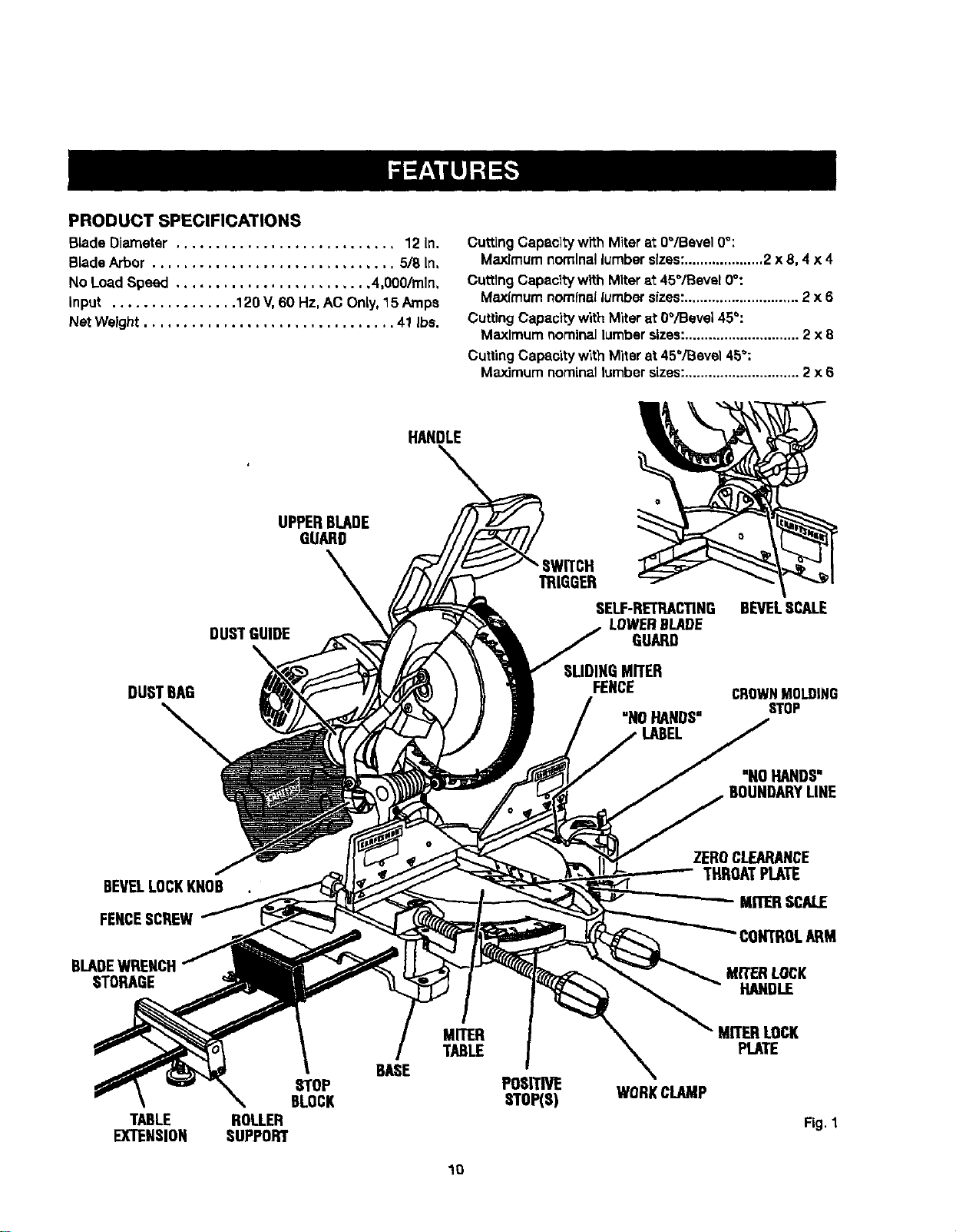
PRODUCTSPECIFICATIONS
BladeDiameter ............................ 12 In.
BLadeArbor ............................... 5/8 in,
No LoadSpeed ......................... 4,000/rain,
input ................ 120 V,60 Hz, AC Only,15 Amps
NetWeight ................................ 41 Ibs.
CuttingCapacityw'rthMiterat 0"/Bevel 0°:
Maximum nominal lumber sizes:....................2 x 8, 4 x 4
CuttlngCapacltywith Miterat 45°/Bevel 0°:
Maximumnominallumbersizes:............................. 2 x 6
CuffingCapacitywith Miterat 0°/Bevel 45°:
Maximumnominallumbersizes:............................. 2 x 8
CuttingCapacitywith Miterat 45°/Bevel 45":
Maximumnominallumbersizes:............................. 2 x 6
HANDLE
DUSTBAG
UPPERBLADE
GUARD
\
DUSTGUIDE
TRIGGER
SELF-RETRACTING
LOWERBLADE
GUARD
SLIDINGMITER
FENCE
"N0 HANDS"
LABEL
BEVELSCALE
CROWNMOLDING
STOP
"NOHANDS"
BEVELLOCKKNOB
FENCESCREW
BLADEWRENCH
STORAGE
ZEROCLEARANCE
THROATPLATE
MITERSCALE
CONTROLARM
MITERLOCK
HANDLE
TABLE
EXTENSION
STOP
BLOCK
ROLLER
SUPPORT
BASE
MITER
TABLE
POSprp_
SToP(s)
WORKCLAMP
MITER LOCK
PLATE
Fig. 1
1O
KNOW YOUR COMPOUND MITER SAW
See Figure1,
Beforeattemptingto use thisproduct,familiarizeyourself
wffhartoperatingfeatures and safety rules.
15 AMP MOTOR
Yoursew hase powerful15 amp belt-drivenmotorwith
sufficientpowerto handletough cuttingjobs. Itis made
with artball bearings, and has externallyaccessiblebrush-
es forease of servicing.
12 in. BLADE
A 12 In. carblde-t/ppedsew blade IsInc./udedwith your
compoundmiter saw.It willout materials up to 4 in,thick
or 7-7/8 in,wide, dependingupon the angleat which the
cutis beingmade.
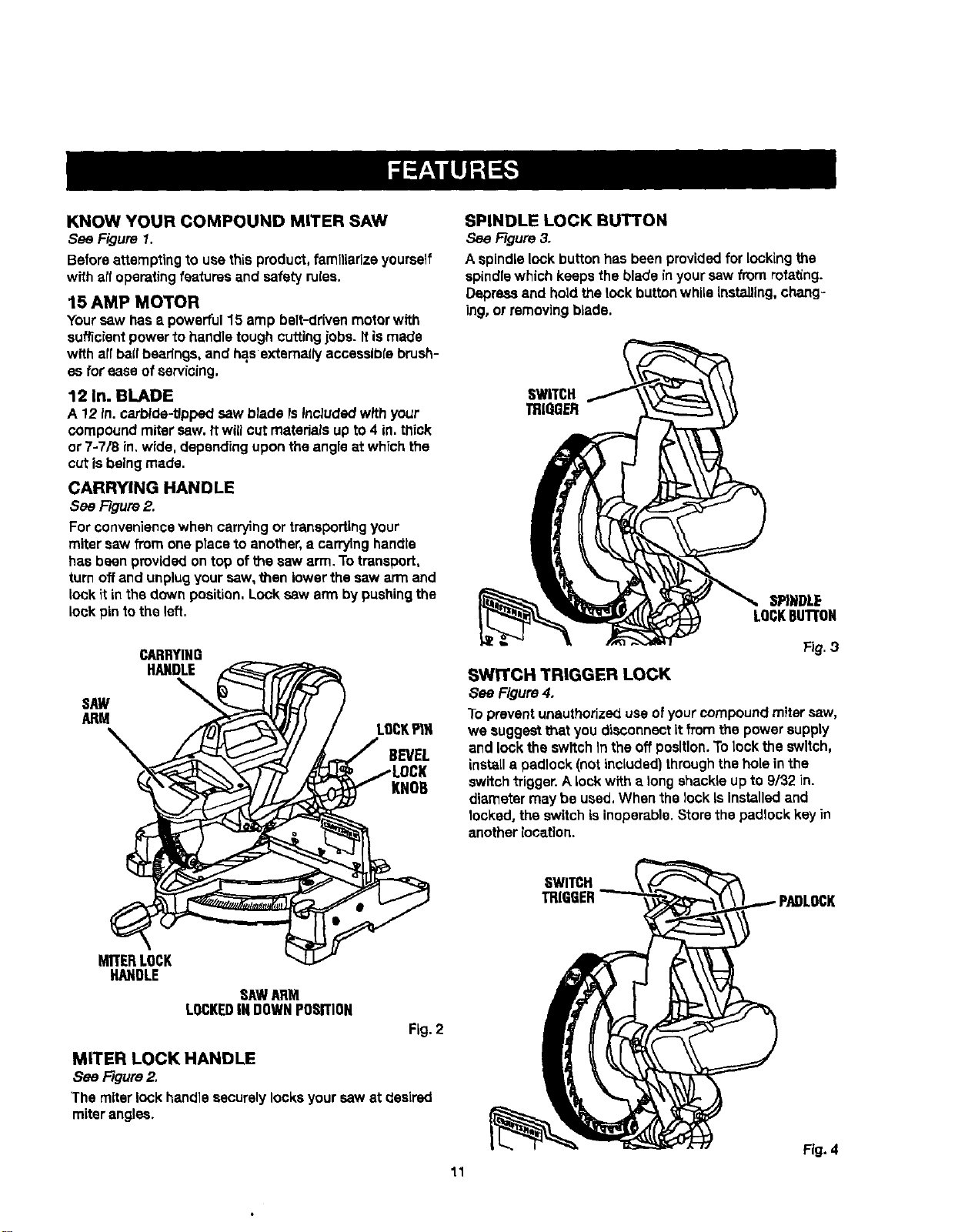
CARRYING HANDLE
See Figure2.
Forconvenience when carryingor tr_nspodingyour
miter saw from one placeto another,a carryinghandie
has been providedontop of the saw arm.To transport,
turn offand unplugyoursaw,then lower the saw arm and
lock it inthe down position,Lock sew arm by pushingthe
lock pin to the left.
SAW
ARM
CARRYING
HANDLE
LOCKP1N
BEVEL
KNOB
SPINDLE LOCK BUTTON
See Figure3.
A spindlelock buttonhas been provided for lockingthe
spindlewhichkeepsthe bladein yoursaw from rota_ng.
Depressand holdthe lock buttonwhile installing,chang-
ing, or removingblade.
SWITCH
TRIOOER
SPINDLE
LOCKBUT[ON
Fig.3
SWITCH TRIGGER LOCK
See Figure,1.
To preventunauthorizeduseofyourcompoundmiter saw,
we suggest thatyou disconnectit from the powersupply
and lock the switchIn theoff position.Tolock the switch,
installa padlock (notincluded)throughthe holeinthe
switchtrigger.Alockwith a longshackleup to 9/32 in.
diametermay be used,When the lock Is installedand
locked, the switchis inoperable.Storethe padlockkey in
anotherlocation.
MITERLOCK
HANDLE
SAWARM
LOCKEDINDOWNPOSITION
Fig. 2
MITER LOCK HANDLE
See Figure2.
The miterlock handlesecurely locksyour saw at desired
miterangles.
SWITCH
TRIGGER
Fig.4
11
LASERTRACTM LASER GUIDE
For more accurate cuts, a LaserTrecTM laser guide is
includedwith yourmitersaw.When used properly,the
laserguide makes accurate, precisioncuttingsimpleand
easy.
POSITWE STOPS ON MITER TABLE
Positivestops havebeen providedat 0°, 15", 22-1/2°,
31.62°, and 45° on boththe left and right sideofthe miter
table.
BEVEL LOCK KNOB
The bevel lock knob securely locksyourcompoundmiter
sew at desired bevel angles.A positivestop adlustment
screwhas been providedon eachaide ofthe saw arm.
These adjustmentscrewsaro for making fine adjustments
at O"and 45",
ELECTRIC BRAKE
An electricbrake hasbeen prov/dedto quicklystop blade
rotationafterthe switchis released.
CROWN MOLDING STOP
The crownmolding stop makes positioningcrownmolding
verticallyagainstthefence easier.
SLIDING MITER FENCE
Hold the workplace securelyagainstthemiter fencewhen
making all cuts. The s_k_ingfeatureallows bothfences0eft
and right)to be moved when making bevel or compour_d
cuts,
Slidethe mltar fences by looseningthe fence screws.
Oncethe desiredpositionofthe miterfence isdeter-
mined, retightenthe fence screwsto securethe sliding
lense.
SELF-RETRACTING LOWER BLADE GUARD
The lower bladeguardIs madeof shock-resistant,see-
throughplasticthat providesprotectionfromeach side
of the blade. It retractsover the upper bladeguard as the
saw IsloweredInto thework.piece.
ROLLER SUPPORT
With the rollersupportinstalled,theworkplacewill glide
smoothlyand levellyover the table extensions.
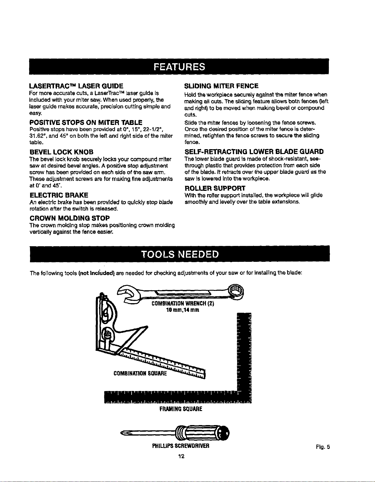
The followingtools/,not Included} are needed for checkingadiustlnentsof yoursaw or for installing the blade:
COMBINATIONWRENCH(2)
10turn,14mm
COMBINATIONSQUARE
FRAMINGSQUARE
PHILLIPSSCREWDRIVER FLg.5
12
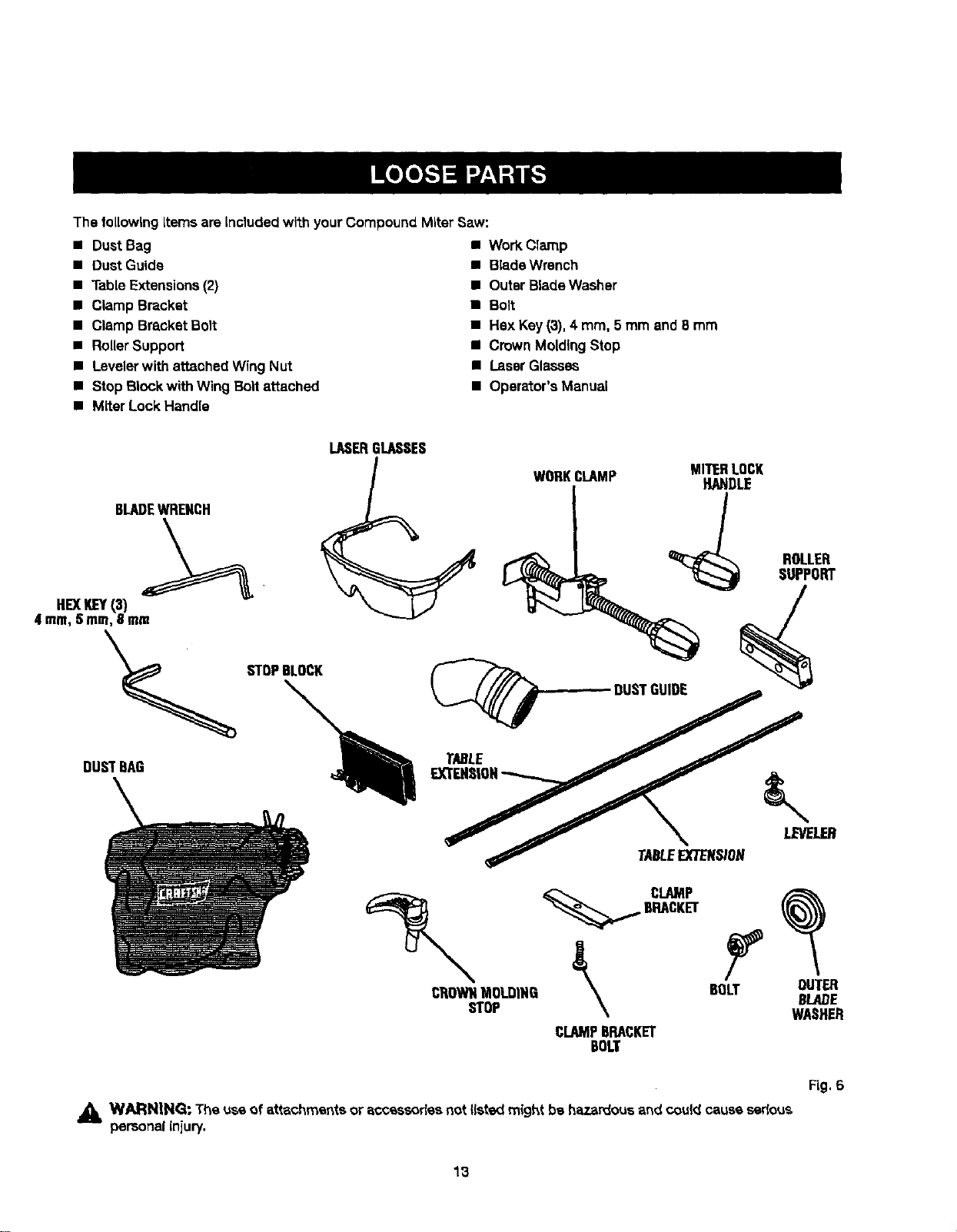
The followingItems are included with your CompoundMiterSaw:
• Dust Bag
• DustGuide
• Table Extensions (2)
• Clamp Bracket
• Clamp Bracket Bolt
• Roller Support
• Levelerwith attached Wing Nut
• Step Block withWing Bolt attached
• Miter Lock Handle
• Work Clamp
• BladeWrench
• Outer BladeWasher
• Boit
• Hex Key(3),4 mm, 5 mm and Bmm
• Crown MoldingStop
• Laser Glasses
• Operator'sManual
BLADEWRENCH
LASERGLASSES
WORKCLAMP MITERLOCK
HANDLE
ROLLER
SUPPORT
HEXKEY{3)
4 ram,5 ram,8 mm
TABLE //
TABLEEXTENSION
_ CLAMP
BRACKET
CI_OWNMOLDING _ BOLT_ OUTERBLADE
STOP WASHER
CLAMPBRACKET
BOLT
Fig, 6
,_ WARNING: The use of attachments or accessories not I(stedmightbs hazardous and couldcausesedous
personalinjury.
13
UNPACKING
This productrequiresassembly.
• Carefullyliftsaw from the cartonby the carryinghandle
and the saw base, and place it ona levelwork surface.
NOTE: Thissaw isheavy.To avoidback injury,liftwith
yourlegs, not yourback, and gethelpwhen needed.
• Thissaw hasbeen shippedwith the saw arm secured
In the down position.To release thesaw arm, push
down onthe top ofthe saw arm, cut thetie-wrap, and
puttout onthe lock pin.
• Liftthe saw arm bythe handle.Hand pressureshould
remainon thesaw arm to preventsuddenrise upon
releaseofthe tiewrap.
• Inspectthe toolcarefullyto make sureno breakageor
damage occurredduringshipping.
• Do not discardthe packingmaterialuntilyou have
carefullyinspected and satisfactorilyoperated1hetoot.
• The saw isfactory set foraccurate cutting.After
assemb)tngit, checkfor accuracy,tt shippinghas
Influencedthe settings,referto specificprocedures
explainedtn"thismanual.
• If any parts are damaged or missing, please call
1-800-932-31B8 for seslstance.
WARNING: If any parts are miSSing,do not operate
thistooluntilthe mlss(ngparts are replaced.Farfure
to do so could resultin posalbteserious personal
injury.
,_1 WARN|NG: Do not attempt to modifythistool
or createaccessoriesnot recommended for use
withthis tool.Any suchalterationor modification is
misuseand couldresultIna hazardouscondition
leading topossibleseriouspersonalinjury.
_IL WARNING: Do not connectto power supply until
assemblyis complete. Failure to complycould result
in accidentalstartingand possibleseriouspersonal
Jnluty.
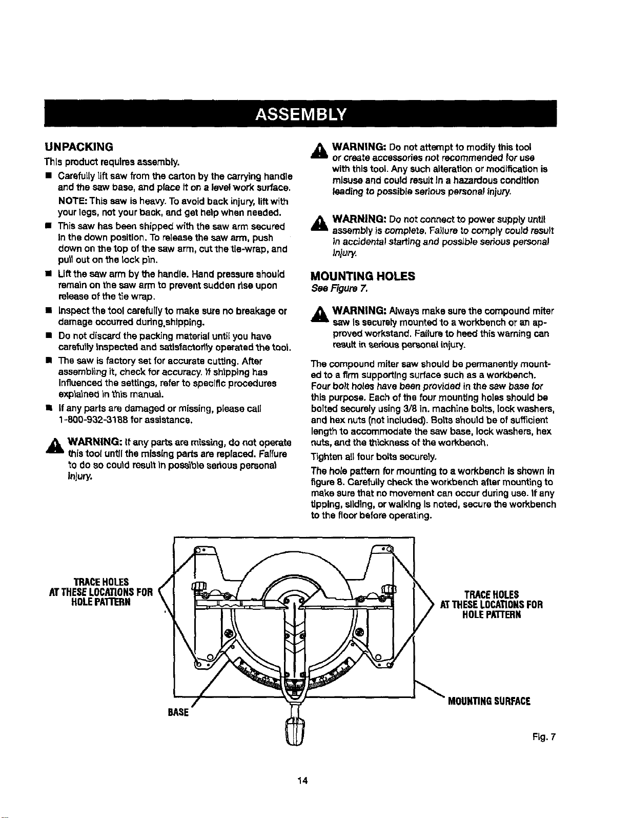
MOUNTING HOLES
SeeFigure7.
,_ WARNING" Alwaysmake surethe compoundmiter
saw Issecurelymountedto a workbenchor an ap-
provedworkstand.Failureto heed thiswarningcan
res_ttin _,eriouspersonaliniury.
The compound mitersaw shouldbe permanentlymount-
ed to a firm supportingsurface suchas a workbench.
Fourboil holeshavebeen provided inthe saw basefor
thispurpose. Eachofthe four mountingho]ssshouldbe
bolted securelyusing3/8 in. machine bolts, lockwashers,
and hex nuts(notincluded). Boltsshouldbe of sufficient
lengthto accommodatethesaw base, lockwashers,hex
nuts, axedthe thickness of the workbench.
Tightenartfour bolts securely.
The holepatternfor mountingto a workbenchIs shownin
figure8. Carefullycheck theworkbenchaftermountingto
make surethat no movementcan occurduringuse. It any
tipping, sliding,or walkingIs noted,securetheworkbench
tothe floor beforeoperating.
"IRACEHOLES _,
ATTHESELOCATIONSFOR
HOLEPATTERN
/
BASE
TRACEHOLES
ATTHESELOCATIONSFOR
HOLEPA'FrERN
MOUNTINGSURFACE
Fig. 7
14
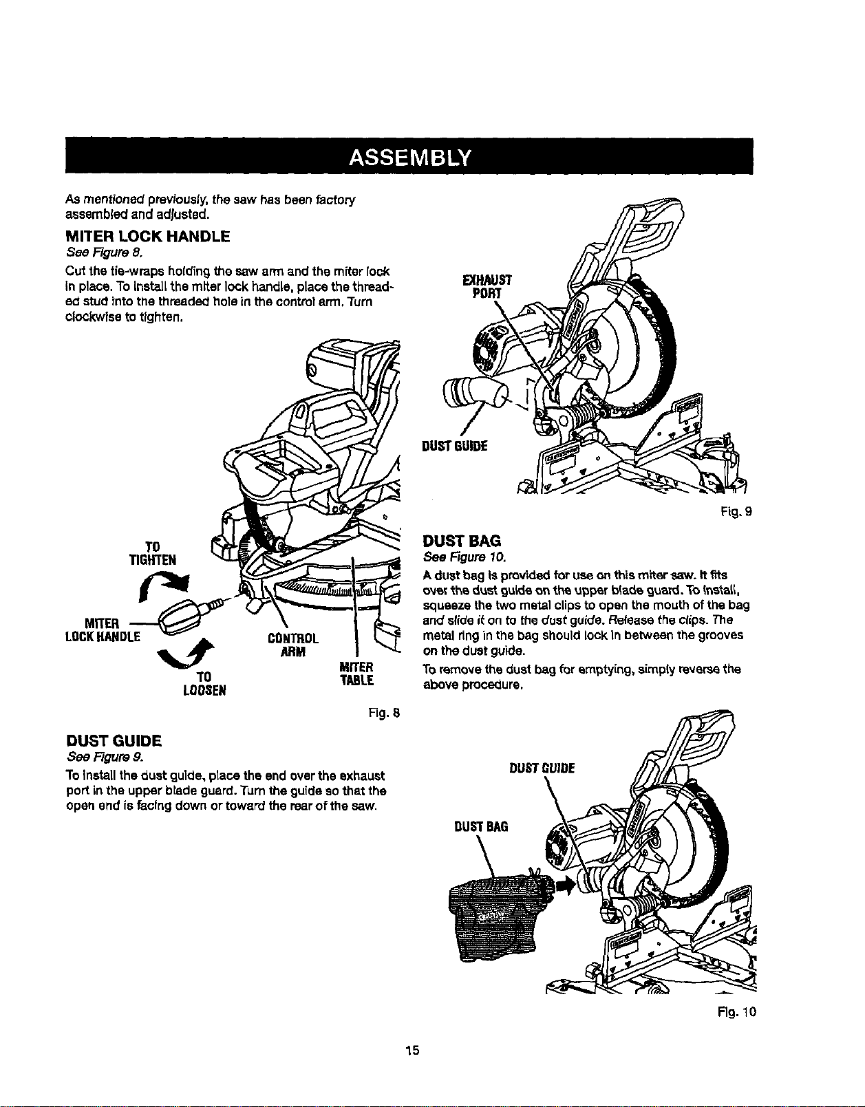
Asmentionedpreviously,thesaw hasbeen factory
assembledand adjusted.
MITER LOCK HANDLE
See Figure8,
Cut the tie-wraps holding the saw armand the miter rock
In place.To Instal[ the miter lookhandle, placethe thread~
ed stud intothe threadedholein the controlerm. Turn
clockwiseto tighten.
EXHAUST
PORT
TO
TIGHTEN
TO
LOOSEN
CONTROL
ARM
MITER
TABLE
Fig. S
DUST GUIDE
See Figure9,
To Installthe dust guide,ptacethe end overthe exhaust
portin the upper bladeguard. rum theguide sothat the
open end isfacingdown ortoward therearof the saw.
Fig. 9
DUST BAG
See Figure 10.
Aduet bag isprovidedfor useonth_smitersaw. Itfits
o'_e_"_h_dustguideor the upper b_adeguam. ToIr,stat_,
squeezethe twometalclipsto open the mouthofthe bag
and slide it on to thedust guide.Releasethe _ips. The
metal ringin the bag shouldlock in between the grooves
on thedust guide.
To removethedust bag for emptying,simplyreversethe
above procsqure.
DUSTBAG
Fig. 10
15
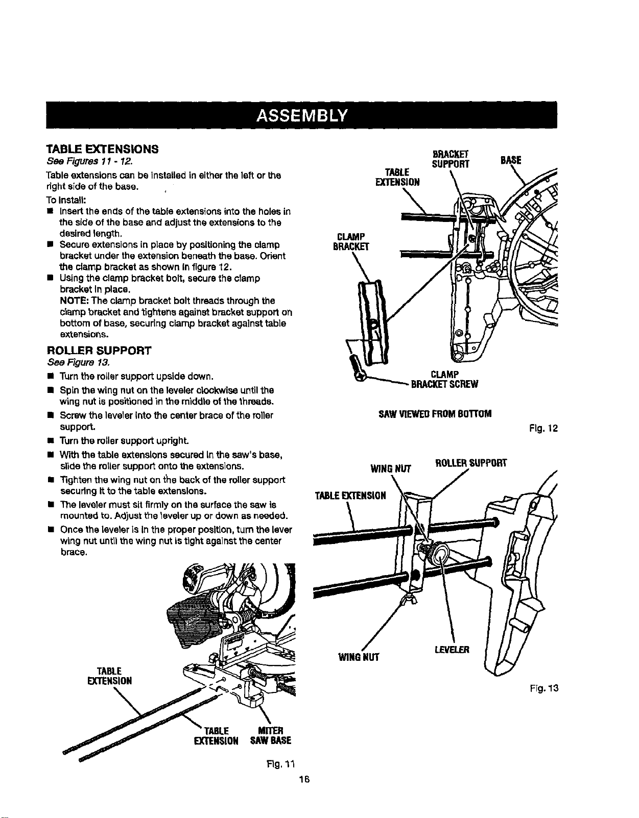
TABLEEXTENSIONS
See Figures11 - 12.
Tableextensionscan beInstalledin eithertheleft or the
fight side ofthe base.
To Instalh
• Insertthe ends of thetable extensionsintothe holesin
the side of the baseand adjustthe extensionsto the
desiredlength.
• Secure extensionsin place by positioningthe clamp
bracket under theextensionbeneaththe base. Orient
the clamp bracket as showninfigure 12.
• Usingthe clamp bracket boil, securethe clamp
bracket In place.
NOTE: The clamp bracketbolt threadsthroughthe
clamp bracket and tightensagainstbracket supporton
bottom ofbase, securing clamp bracketagainsttable
extensions.
ROLLER SUPPORT
See Figure 13.
• Turnthe rollersupportupsidedown.
• Spinthe wing nuton the levelerclockwiseuntilthe
wing nutis positionedin the middle ofthe thre=ds.
• Screwthe levelerintothe center brace ofthe roller
support.
• Turnthe reliersupportupright.
• Withthe table extensionssecuredInthe saw's base,
slidethe miler support onto the extensions.
• Tightenthe wingnut on the back ofthe rollersupport
secudngItto the table extensions.
• The levelermustsit firmly on the surfacethe s_w is
mountedto. Adjust the leveler up or down as needed.
• Oncethe leveleris inthe properposition,turnthe lever
wing nut untilthewing nut istightagalnstthe center
brace.
TABLE
EXTENSION
BASE
CLAMP
BRACKET
CLAMP
BRACI(ETSCREW
SAWV1EWEDFROMBOTTOM
WINGNUT ROLLERSUPPORT
TABLEEXTENSION
Fig. 12
TABLE
EXTENSION
WINGNUT
LEVELER
Frg. 13
FABLE MITER
EXTENSION SAWBASE
Fig. 11
16

_lb WARNING: When usingthework clampwith the
stop block, installthe clamp on thesame side as the
stop block. Thiswill ellmlnatethe posslb(tityoftmp-
p]ngtheworkplece, resulting Inthe saw blade and
workpiece kickingup. Failuretoheed this warning
can resultin sedouspersonalInjury,
STOP BLOCK
See Figure 14.
The stop blockisusefulas a stop for makingrepetitive
cutsto the same length.Itcan be instaltedon eitherside
of the saw base:
• Slidethe stop block onthe table extension.
• Adjustthe stop block the desired distancefrom the
bladefor the cutto be made.
• TightensmallwLngscrewto securethe stop blockto
the table extension.
• Make a test cut inscrap material and measure the
lengthof the workpiece.
• Make any necessaryadjusb_enta.
WORK CLAMP ASSEMBLY
See F/gum 15,
The work clamp providesgreater controlby clampingthe
workp_eceto the fence or the saw table. It alsoprevents
theworkplecefrom creepingtowardthe saw blade, ThisIs
veryhelpfulwhen cuttingcompound miters.
Dependingon the cuttingoperationand the size ofthe
workpiece, it may be necessaryto use a C-clamp rnstead
of thework clamp to secure the workpiece priorto ma_ng
the cut.
A WARNING: In s_me operations,thework clamp
assemblymay interferewith the operationofthe
bladeguardassembly.Always make surethere Isno
interferencewith the blade guard pdor tobeginning
any cutt(ncJoperat(on to reducethe dskof sedous
personalinlury.
To Installthework clamp:
• Placethe shell ofthe work clamp In eitherholeonthe
saw table base.
• Rotate the knobon the work clamp to moveit in or out
as needed or pressthe quickreleaselevertot faster
positioning.
TO INSTALL BLADE
See Figures 16 - 18,
_l WARNING: A 12 k_.'blade Lsthe rru_xkTtumblade
capacity ofthe saw.Neverusea bladethatIstoo thick
to allowouter blade washer to engagewith the fiats
onthespindle,Largerbladeswillcome Incontactwith
the b|ade guards,whilethickerbiades w'Lllpreventthe
blade screw from securingthe blade on the spindle,
Either of these situations could result in a serious
_sok_,entend can cause serlouspersonaliniury,
17
STOP
BLOCK
TABLE
EXTENSION
MITER
SAWBASE
WORK
CLAMP
Fig. 14
F_9.15
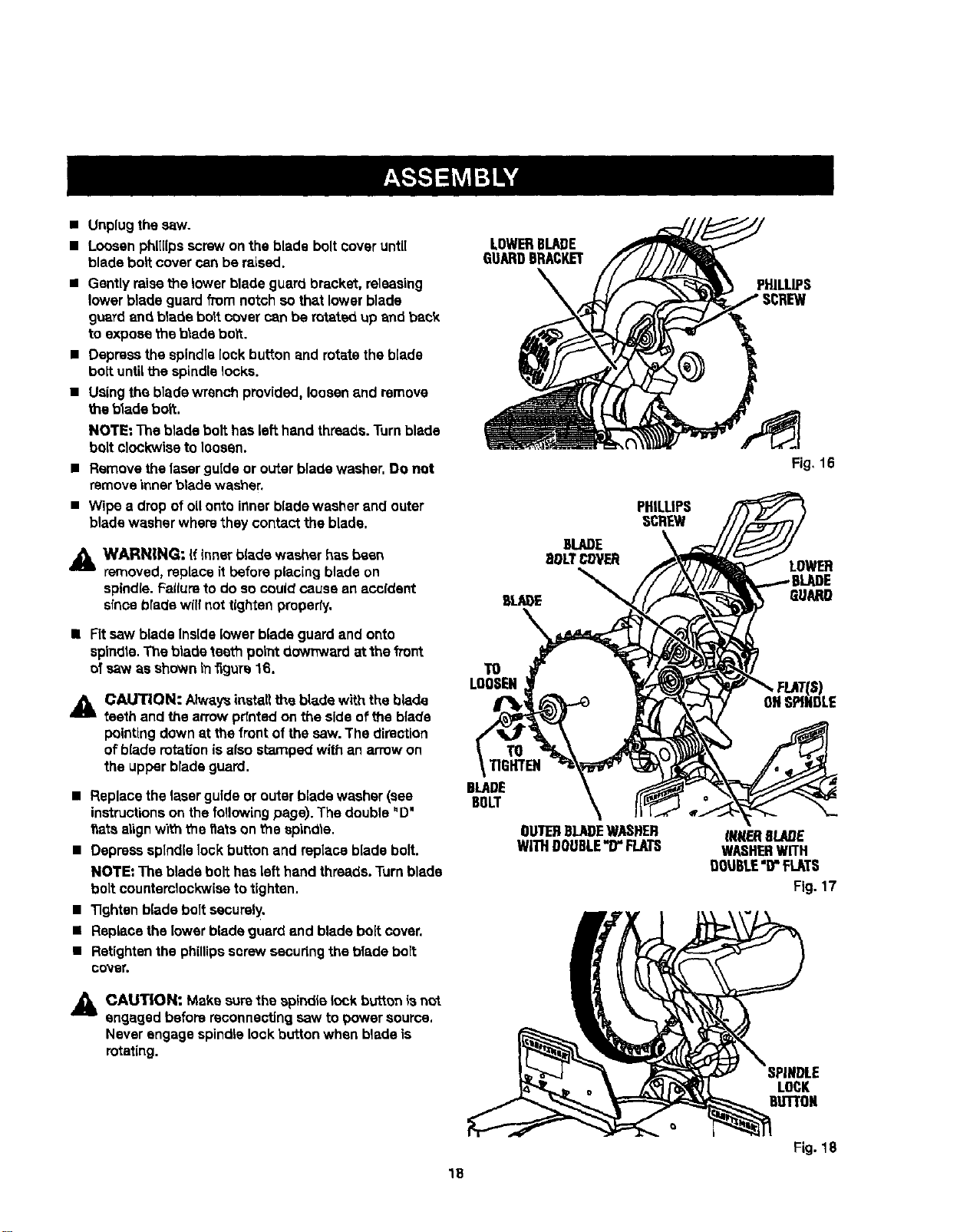
• Unplugthe saw.
• Loosenphillipsscrewon theblade boltcover until
blade boll cover canbe raised.
• Gently raisethe lower blade guard bracket,releasing
lowerblade guard from notchsothat lower blade
g_xardand blade boltcover canbe rotated up and back
to expose the bladebolt.
• Depressthe spindlelock button and rotatethe blade
bolt until Me spindlelocks.
• Using the blade wrench provided, loosen and remove
the bladebert.
NOTE: The blade bolthas left hand threads.Turnblade
boltclockwiseto loosen.
• Removethe laserguide or outerblade washer.Do not
removeinnerbtade washer.
• Wipe a drop of oUonto innerblade washer and outer
blade washer wherethey contact the blade.
A
WARNING: If Innerb(ade washer hasbeen
removed, replaceit before placingblade on
spindle.Failureto do so could cause an accident
slnca brede willnot tightenproperty.
II Fitsew blade Inside lower blade guardand onto
spindle.The blade teeth point downwardat the front
ofsaw as shownin_guTs16.
A CAUTION: Alwaysinstall the bladewith the blade
teeth and the arrowpdntedon the sideof the blade
pointingdownat thefrontofthe saw.The direetion
ofblade rotationisalso stamped with an arrowon
the upperblade guard,
• Replacethelaser guide or outer bladewasher (sea
instructionson thefollowing page). The double"D"
f_atsalignwiththe flats on the spindle.
• Depressspindlelock button and replacebladebolt.
NOTE: The bladebolt hasleft handthreads.Turnblade
boltcountemlockwiseto tighten.
• Tightenblade boltsecurely,
• Replacethe lower bladeguard and bladeboltcover.
• Retightenthe phillipsscrewsecudngthe blade bolt
COV8_
LOWERBLARE
GUARDBRACKET
TO
LOOSEN
TO
TIGHTEN
BLADE
BOLT
OU'IETIBLADEWASHER
WITHDOUBLE"D"FLATS
PHILLIPS
Fig, 16
LOWER
GUARD
_NRERBLADE
WASHERWITH
DOU6LE"D"FLATS
Fig. 17
,,_& CAUT|ON: Make surethe spindlelock button ia not
engaged beforereconnectingsaw to power source.
Neverengagespindlelock button when bladeis
rotating.
IPINDLE
LOCK
OLIn'ON
Fig. 18
18
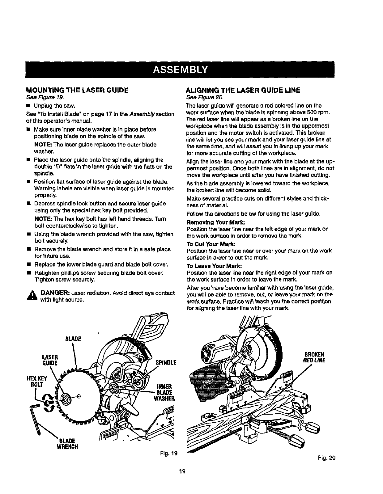
MOUNTING THE LASER GUIDE
See Figure 19.
I Unplug thesew.
See "ToInstallBlade"on page 17 in the Assemb/yssct[on
of thisoperator'smanual.
• Make sureinnerblade washerIs In place before
positioningbladeon the spindleofthe saw,
NOTE: The laserguide replacesthe outer blade
washer.
• Placethe laser guideontothe spindle,aligningthe
double"O"f_ateinthe laser guidew_th"the_a_.sonthe
spindle.
• Positionflat surface oflaser guideagainsttheblade.
Warninglabelsarevisible when ia.serguide Ismounted
properly.
• Depress spindlelock button and securelapserguide
usingonlythe specialhex key boltprovided.
NOTE"The hexkey bolt haslefthandthreads.Turn
bolt counterclockwisetotighten.
• Usingthe blade wrenchprovidedwith the saw, tighten
boltsecurely,
• Removethe blade wrenchand storeit ina safe place
for futureuse.
• Replacethe lowerbladeguard and blade boltcover.
• Retightenphillipsscrewsecuringblade boltcover.
Tighten screw securely.
_i DANGER: Laserradiation.Avoiddirecteye contact
with lightsource.
ALIGNING THE LASER GUIDE LINE
See Figure20.
The laserguidewit]generatea red coloredlineon the
work surfacewhen the b}adeis spinningabove500 rpm.
The red laserlinewillappearas e brokenlineon the
workplacewhen the bladeassemblyIsin the uppermost
positionand the motorswitchIsactivated.Thisbroken
line willletyou see yourmark and yourlaser guide fineat
thesame time, 8ttdwillassist youin lining up yourmark
lor more accurate cuttingof theworkplace.
Alignthe Lasertinsand yourmark with the bladeat the up-
permostposition.Once bothlinesare inalignment,do not
movethe workplaceuntLLafteryou havefinished cutting.
Asthe bladeassembly isloweredtowardtheworkplace,
thebroken linewillbecome solid.
Make severalpracticecuts on differentstylesandthick-
nasaof material.
Foflowthe directionsbelow forusingthe Laserguide.
Removing Your Mark:
Po._ttionthe laser line nearthe left edge ofyour mark on
the work surfacein orderto removethe mark.
ToCut Your Mark:
Positionthelaserlinenear or overyourmarkon thework
surfaceinorderto cutthemark.
To Leave Your Mark:
Positionthelaserlinenear the rightedge ofyourmarkon
thework surfaceIn orderto leavethe mark.
Afteryou have become fam_larwith ostngthe laser gutde,
youwillbe able to remove,cut, or leaveyour mark onthe
wor_ surface.Practtoew_ teach yo_ the correctpos_'_on
foraligningthe laserlinewith yourmark.
BLADE
LASER
GUIDE SPINDLE
BROKEN
REOLtNE
HE)(KEY
BOLT
_BLADE
WRENCH
INNER
BLADE
WASHER
Fig. 19
Fig. 20
19
NOTE:Manyoftheillustrationsinthismanualshowonly
porttonsofthecompoundmitersaw.ThisIsIntantEonalso
thatwecanclearlyshowpointsbeingmade in the
illustrations.Never operate your saw without all guards
securely In grace and rn good operating condition.
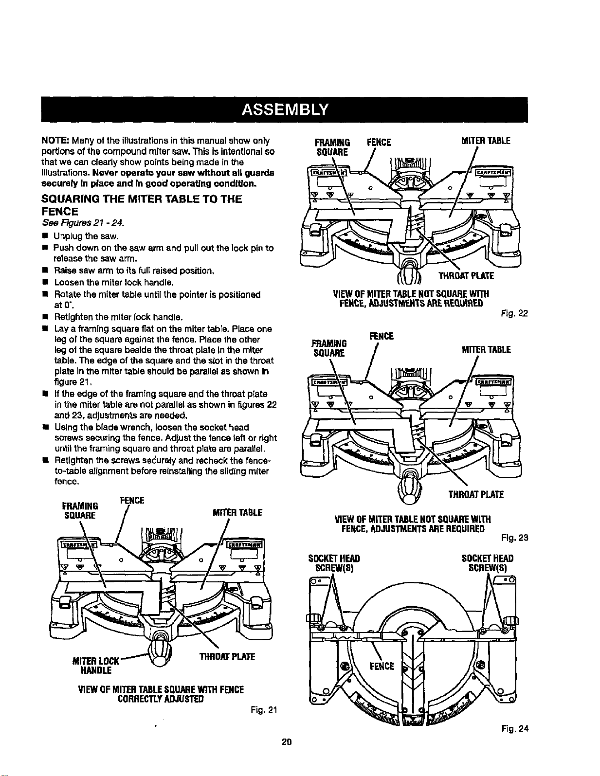
SQUARING THE MITER TABLE TO THE
FENCE
See F/gums21 - 24.
• UnpLugthe saw.
• Pushdown on thesaw arm and pullout thelock pinto
releasethe saw arm.
• Raise saw arm toits full raisedposition.
• Loosenthe miter lock handle.
• Rotatethe miter table untilthe pointeris positioned
atO'.
• Retightenthe miterlock handle.
• Laya framing squarefiaton the miter table.Placeone
legof the squareagainstthe fence. Place theother
legof the squarebesidethethroat plateIn the miter
table. The edge ofthe squareand the slotin thethroat
plate inthe mitertable shouldbe parallelas shownin
figure21,
• Ifthe edge of theframlng squareand the throatplate
inthe miter table are notparallelas shownin itgures22
and 23, adjustmentsareneeded.
• Usingthe bladewrench, loosenthe sockethead
screwssecuringthefence. Adjustthe fencelefl or right
untilthe framingsquareand throat plata am parallel.
• Retigbtanthe screwssecurelyand recheckthe fence-
to-table alignment beforereinstallingthe slidingmiter
fence.
FENCE
FRAMING
SQUARE MITERTABLE
FRAMING FENCE MITERTABLE
SQUARE
THRUATPLATE
VIEWOFMITERTABLENOTSQUAREWITH
FENCE.AQ-tUS-'Th_EXTSAPEREQUWLED
Fig,22
FENCE
FRAMING / MITERTABLE
. ,go
VIEWOFMITERTABLEHOTSQUAREWITH
FENCE,ADJUSTMENTSAREREQUIRED
Fig. 23
SOCKETHEAD SOCKETHEAD
SCREW(S) SCREW(S)
THROATPLATE
NAPDLE
VIEWOFMITERTABLESQUAREWITHFENCE
CORRECTLYADJUSTED
Fig.21
Fig, 24
2D
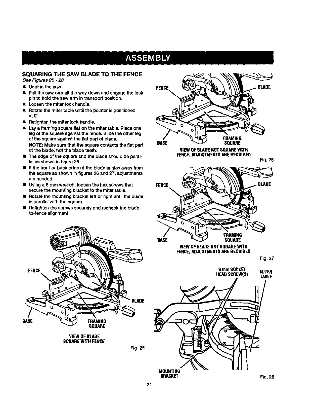
SQUARING THE SAW BLADE TO THE FENCE
See Figures25 - 28,
• Unplugthe saw.
• Pull the saw arm all theway downand engagethe look
pinto holdthe saw arm in transportposition,
• Loosenthe miter lock handle,
• Rotatethe miter table untilthe pointerispositioned
at0".
• Retightenthe miterlock handle.
• Laya framingsquarefiat onthe miter table. Placeone
leg ofthesquare againstthe fence, Slidethe otherleg
ofthe squareagainstthe flatpad ofblade.
NOTE: Make surethat the squarecontactsthe fiat part
of the blade, nottheblade teeth.
• The edge of thesquareand the blade shouldbe paral-
lel as shownin figure25.
• Ifthe front or back edge of the blade angles away from
the square as shown in figures 26 and 27, adjustments
areneeded.
• Using a 8 mrn wrench, loosenthe hex screwsl_at
securethe mounting bracket to the mlter table.
• Rotate the mounting bracketleft or dght untilthe blade
isparallelwith the square. '
• Retfghtanthe screwssecure(yand recheckthe blade-
to-fence alignment.
FENCE
FRAMING
BASE :SQUARE
FENCE
VIEWOFBLADENOTSQUAREWITH
FENCE,A[_JU6I"MENTSAREREQtIIRED
FRAMING
BASE SQUARE
VIEWOFBLADENOTSQUAREWITH
FENCE,ADJUSTMENTHAREREQUIRED
8 mmHO_KET
HEADSCREW(S)
BLADE
Fig.26
6LADE
Fig. 27
MITER
TABLE
BASE FRAMING
HQUARE
_EW OFBLADE
SQUAREWITHFENCE
Fig. 25
MOUNTING
BRACKET
2S
21
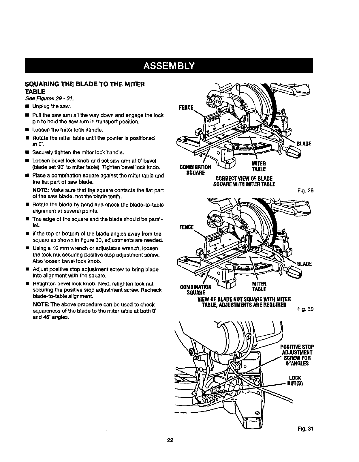
SQUARING THE BLADE TO THE MITER
TABLE
See Figures29 - 31.
• Unplugthe saw.
• Pull the saw arm all the way down and engage the 1ock
pin to hold the saw arm in transport position,
• Loosen the miter lock handle.
• Rotate the mitertable untilthe pointerispositioned
at0",
• Securelytighten themiter lock handle.
•Looeen bevel lock knoband setsaw arm at 0"bevel
(bladeset 90' to mltertable}, Tightenbevellock knob,
• Placea comb(nationsquareagainstthe mitertable and
thefiat part of saw blade.
NOTE: Make surethatthe square contactsthe fiatpar_
ofthe saw blade,not "thebladeteeth.
• Rotate the blade by hand and cheCk the blade-to-table
alignment at several points,
• The edge of the square and the blade should be paral-
lel.
• If thetop or bottom ofthe bladeanglesaway from the
squareas shownin figure30. adjustmentsare needed.
• Usinga 10 mm wrench or adjustable wrench, loosen
the lock nut securingpositivestopadjustmentscrew.
/_eeloosenbevellockknob.
• Adjustpositivestop adjustmentscrewto bring blade
Into alignmentwith the square.
• Retightenbevel lock knob. Next, retightenIook nut
seCuringthepositivestop adjustmentscrew.Recheck
blade-to-table alignment.
NOTE: The above procedure can be used to check
squareness of theblade to the mitertable at both 0"
and 45" angles.
FENCE
MITER
TABLE
CORRECTViEWOFBLADE
SQUAREWITHMITERTABLE
FENCE
MITER
COMBINATION TABLE
SQUARE
VIEWOFBLADENOTSQUAREWITHMITER
TABLE,ADJUSTMENTSAREREQUIRED
Fig. 29
"BLADE
Fig.30
POSITIVESTHP
ADJUSTMENT
SCREWFOR
O°ANGLES
LOCK
NUT(S)
Fig. 31
22
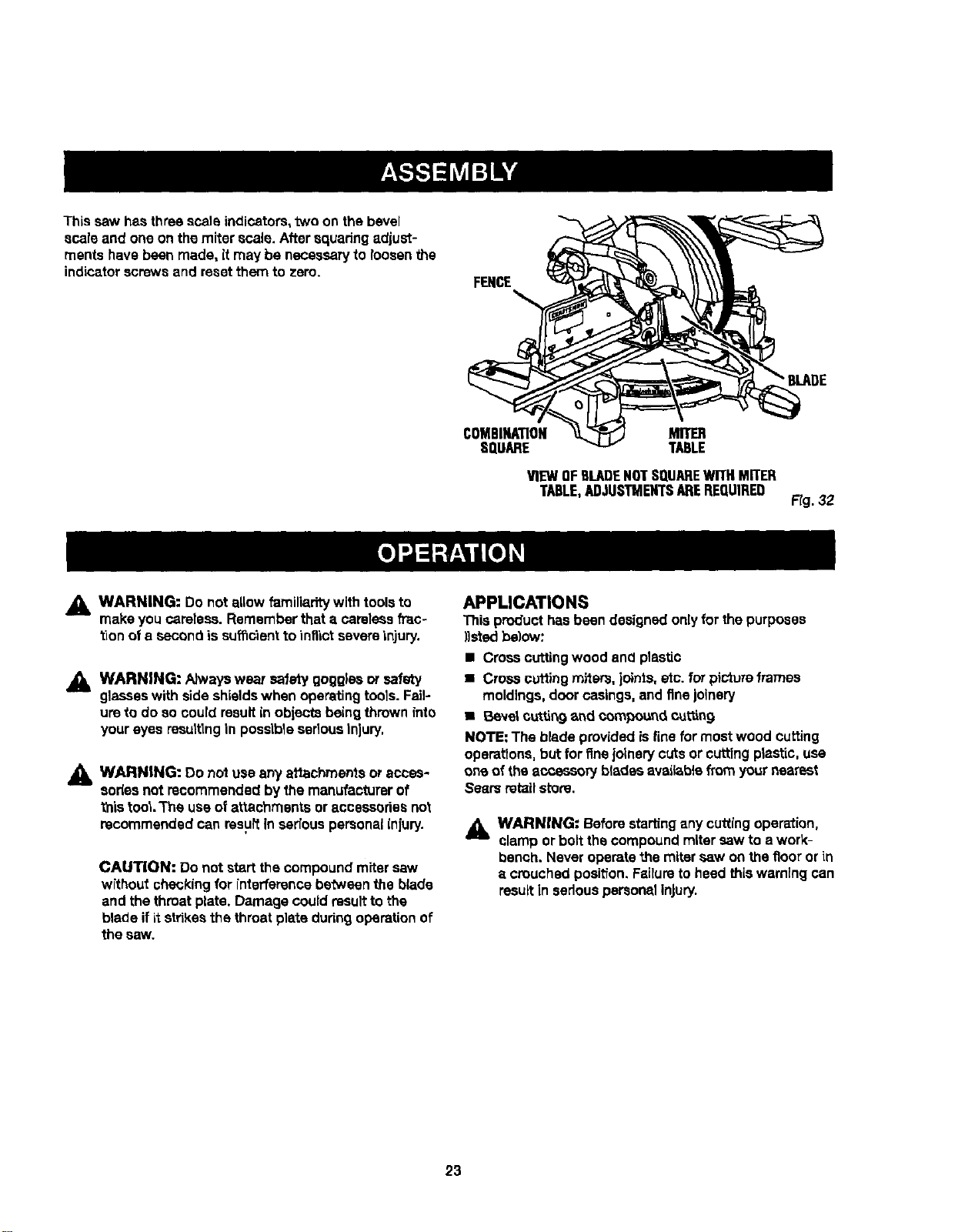
Thiscaw hasthree scale indicators,two on the bevel
scale and one on the miterscale. After squadng adjust-
ments havebeen made, itmay be necessaryto loosenthe
indicatorscrewsand resetthem to zero.
FENCE
• BLADE
COMBINATION
SQUARE
MITER
TABLE
VIEWOFflLADENOTSQUAREWITHMITER
TABLE,ADJUSTMENTSAREREQUIRED
Fig. 32
_k WARNING: Do notallowfamiliarity with toolsto
make you careless.Rememberthat a carelessfrac-
tionofe secondis sufficient to inflict severeinjury.
_k WARNING: Alwayswsar safety goggFsaor safety
glasseswith side shieldswhen operatingtools. Fail-
umto do socould resultin objectsbeingthrown _nto
youreyes resultingin possibleseriousInjury.
_, WARNING: Do notuse anyattachments oracces-
sories not recommended bythe manufacturerof
this tool.The useof attachments or accessoriesnot
recommendedcan resultin seriouspersonalinlury.
CAUTION: Do not startthe compoundmiter caw
without checkingfor interference betweenthe blade
and thethroat plate.Damage couidresultto the
blade ifitstrikesthe throatplate dudngoperationof
the saw,
APPLICATIONS
This producthasbeen designedonlyfor the purposes
)}stedbelow:
• Cresscuttingwood and plastic
• Crosscuffing miters, joints,etc. for pictureframes
moldings,doorcasings,and finejolnery
• Beve_cu_.tin9and compouncLcuing
NOTE: The bladeprovidedisfine for mostwood cutting
operations,butfor fineJoinerycutsor cuttingplastic, use
one of theaccessory bladesavaiisb_efromyournearest
Searsretailstore.
_k WARNING: Beforestartingany cuttingoperation,
clamp or boltthe compoundmitersaw to a work-
bench, Neveroperatethe miter saw onthe floor or in
e crouchedposit'ion.Failuretoheed thiswarningcan
resultIn sedouspersonalinjury.
23
NOTE: Always check for interference between the blade
and the silding miter fence BEFORE attempting to make
a cut. Some compound miter cuts rsquim the sliding miter
fence to be moved or completely removed before making
the cut.
CUTTING WITH THE (_OMPOUND MITER
SAW
_lb WARNING: Whenusinga work c_mp or C-clamp
to secure theworkpiece,clamp workplace on one
side of the bladeonly.Theworkplece must remain
fTeeon one side ofthe bladeto preventthe blade
from bindingIn workplece.The workplace bindlng
the blade w_llcausemo'torstallingand idckback. "This
situationcould causean accident resultingin pos-
sibleserious personalinjury.
Fig. 33
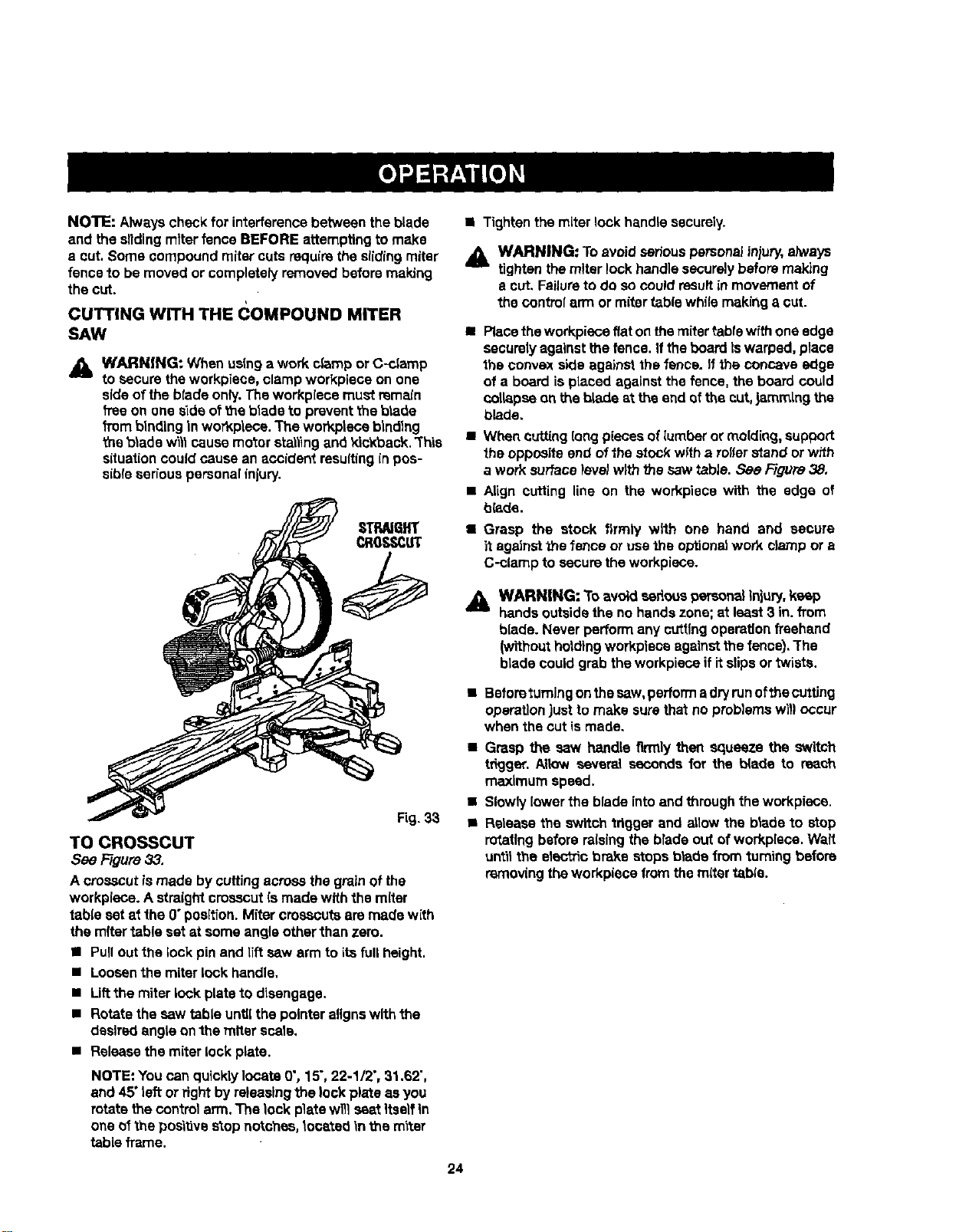
TO CROSSCUT
See Figure33.
A crosscutismade bycuffingacrossthe grainof the
workplace.A straightcrosscutismadewith the miter
table set at the 0" position.Mitercrosscutsare madewith
the mitertable set at some angleotherthan zero.
• Pullout the lock pinand lift sew arm to itsfullheight.
• Loosenthe miter lock handle.
• Lift the miter lock plate to disengage.
• Rotate the saw table until the pointer aligns with the
desired angle on the miter scale.
• Release the miter lock plate.
NOTE: You can quicklylocate O',15",22-1/2",31.62",
and 45" left orfight byreleasingthe lockplate as you
rotate thecontrolarm. The lock platewillseat itself In
one ofthe positivestopnotches, located _nthe m'_ter
table frame.
• Tighten the miter lock handle securely.
_1. WARNING: To avoidserious personalinjury,always
tightenthemiter lock handle securelybefore making
e cut. Failureto do so couldresultin movementof
the controlarm or mitertablewhilemakinga cut.
• Placetheworkplaceflat onthemiter table withone edge
securelyagainstthefence. If the boardIswarped, place
the convexside againstthe fence. If the concave edge
of a board isplaced againstthe fence,the board could
collapseonbe blade at the end af the cut,jammingthe
blade.
• Wt_tn cutting(ongpieces oflumber or molding, support
the oppositeend ofthe stockwffha roller stand or wffh
a work surfacelevel with the sawtabJe.Sac Figura 38,
Align cutting line on the workpiece with the edge of
blade.
Grasp the stock firmly with one hand and secure
it against the fence or use the optional work clamp or a
C-clamp to secure the workplace.
WARNING: To avoid eedous personalinjury,keep
handsoutsidethe no handszone;at least3 in. from
blade. Never performany cuttingoperationfreehand
(withoutholdingworkplaceagainst the fence),The
bladecould grabtheworkplace ifitslipsortwists.
• Beforo turning on the saw, perform adry run ofthe cuttJng
operation just to make sure that no problems will occur
when the cut is made,
• Grasp the saw handle firmly then squeeze the switch
tdgger. Allow several secondsfor the blade to reach
maximum speed.
• Slowlylower the blade intoand through the workplace.
• Release the switchtrigger and aiidw the blade to stop
rotatingbeforeraisingthe bradeout ofworkplace.WaR
untilthe electricbrake stops b_de from '_umingbefore
removingtheworkplacefrom themiter tsbie.
24
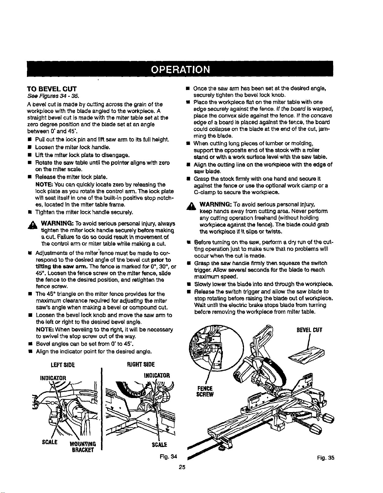
TO BEVEL CUT
See Figures34.35.
A bevel cutis made by cuttingacrossthe grain of the
workpiece with the bladeangled to the workpiece.A
straightbevel cut Is made withthe miter tableset at the
zero degreepositionand theblade set at an angle
between 0"and 45",
• Pullout the lock pin and riftsaw armto itsfull height.
• Loosenthe miterlock handle.
• Liftthe miter lock platsto disengage.
• Rotate the saw table untilthe pointeralignswith zero
on the miter scats.
• Release the miterlock plate.
NOTE: You canquicklylocate zeroby releesingthe
lock plate as you rotatethe controlarm. The lock plate
willseat itselfin one ofthe built-in positivestop notch-
es, locatedInthe miter table frame.
• Tightenthe miter lockhandle securely.
Jl_ WARNING: To avoid serous personalinju_, always
tighten the miterlock handlesecurelybeforemakin_
a cut. Failureto do so coutdresu_.Inmovement of
the controlarmor miter tablewhite making a cut,
i
• Adjustmentsofthe miterfence must be made to cop
respondto the desiredangle ofthe bevel cutprior to
tilting the saw arm. The fence ismarked for 0=,30°, or
45°. Loosenthe fencescrew onthe miter fence, slide
thefence to the desiredposition,and retlghtanthe
fence screw.
• The 45° triangleon the miterfence providesfor the
maximumclearancerequired for ad)ustlngthe miter
saw'sanglewhen makinga bevel orcompound cut.
• Loosenthe bevellock Knoband movethesaw armto
the left ordght tothe desiredbevel angle.
NOTE=When bevelingto the right,itwill be necessary
to swivelthe stop screwout ofthe way.
• Bevelangles can be set from 0"to 45".
• Alignthe indicatorpointfor the desiredangle.
LEFTSIDE RIGHTSIDE
INDICATOR INDICATOR
• Once the saw arm has been set at the desired angle,
securely tighten the bevel lock knob.
• Place the workpiece fiat on the miter table with one
edge saCuTely against the fence, if _hs board is warped,
place the convex side against the fence. _fthe concave
edge of a board is placed against the fence, the board
could collapse on the blade at the end of the cut, jam-
ming the blade.
• When cuffing tong pieces of lumber or molding,
support the opposite end ofthe stock wWna rotter
stand or with a work sudece level with the saw table.
• Align the cutting line on the workpiece with the edge of
sew blade.
• Grasp the stock firmly with one hand and secure it
against the fence or usa the optional work clamp or a
C-clamp to secure the workpiece.
_1= WARNING: To avoidseriouspersonalInfury,
keep handsaway from cuttingarea. Neverperform
any cutting operation freehand (without holding
workpiece ag_'cnst the fence). The blade could grab
the ,_orkp'_co _fitslips or twists.
• Beforeturningonthe saw. p_rforma d_ runofthe cut-
ting operationJus_to make sure thatno problemswitl
occurwhen the cutis made.
• Graspthe sew handlafirmly then squeezetheswitch
trigger,Allow severalsecondsfor the bladeto reach
maximum speed.
• S_owlylower the b_de Into and throughthe workplace.
• Releasetheswftchtriggerand allow the sew bladeto
stop rotaling beforeraisingthe bla_e out ofworkptsce.
Wa_tuntilthe electricbrake stopsblade from turning
beforeremovingthe workplacefrom mitertable.
BEVELCUT
SCALE
Fig,35
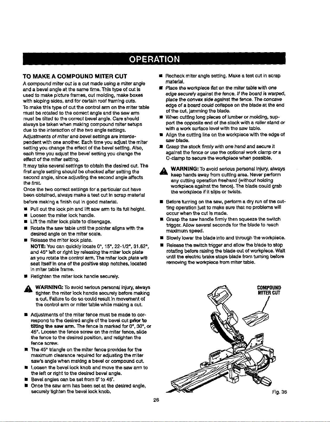
TO MAKE A COMPOUND MITER CUT
A compound mitercut isa cut made usinga miterangle
and a bevelangle at the same time, Thistype of cutIs
used to make pictureframes, cut molding, make boxes
with slopingsides,end for certainroofframfng outs.
To make thistype of cutthe control arm on the mitertable
mustbe rotatedto the correctangle and the sew arm
must be dited to the correctbevelangre,Care should
always be takenwhen making compoundmitersetups
due to the interactionof the twoangle settings.
Adjustmentsofmiter and bevel settingsare interde-
pendentwith one another.Eachtimeyou adjustthemiter
settingyou changethe effect ofthe bevelsa_ng. Also,
each time you edlust the bevelsettingyouchange the
effect of the miter settfng.
It may take severalsettingsto obtainthe desiredcut. The
firstangresettingshouldbe checkedafter settingthe
second angle, sinceadjustingthe secondangleaffects
the first.
Once the two correctsettingsfor a particular cut have
been obtained,always make a test cut in scrap material
beforemakinga finish cut in good material.
• Pullout the lock pinand [fitsaw armto itsfull height.
• Loosenthe miter lock handle.
• Liftthe miter lock plate to disengage.
• Rotate thesew table untilthe pointeralignswith the
desiredangle onthe miter scale,
• Releasethe miter lock plate.
NOTE: You can quickly locate 0°, 15°, 22-1/2°, 31.62°,
and 45° left or dghtby releasingthe miter lock plate
as you rotatethe control arm.The miter lock platewill
seat ItselfIn one ofthe positivestop notches,locateq
in mitertable h'ame.
• Retightan the miter lock handle securely.
• Recheckmiter anglesetting.Make a test cut in scrap
material.
•PIsce the workplaceflat on the rarer table withone
edge security againstthe fence. It the board is warped,
place the convex sideagainstthe fence. The concave
edge of a boardcould coffapea onthe b_adeat theend
ofthe cul,jammingthe blade.
• When cuttinglongpiecesof lumber or molding, sup-
port theoppositeend of thestockwitha rollerstand or
with a work surfacelevelwith thesaw table.
• ALignthe cuttinglineon theworkpiece with the edge of
saw b_de.
• Graspthe stockfirmly with one handand secure it
againstthefence or usethe optional work clamp ora
C-clamp to securethe workplacewhen possible.
_, WARNING: Toavoidsedous personalinjury, always
keep handsaway from cuttingarea. Never perform
any cuttingopera_'onfreehand(wRhoutholding
workpiecaagainst the fence),The bradacouldgrab
theworkpiece ifit slipsor twists.
• Before turning on the saw, perform a dry run of the cut-
ting operation just to make sure that no problems will
occur when the cut Is made.
• Grasp the saw handle firmly then squeeze the switch
trigger. Allow several seconds for the blade to reach
m_mum spewed.
• Slowly lower the blade into and through the workpiece,
• Release the switch trigger and allow the blade to stop
rotating before raising the blade out of workplace. Walt
u_til the e_ectdc b_ke stops blade from turning before
removing the won_pieee horn miter table.
_, WARNING: To avoid seriouspersonallnju_/,always
tighten themiter lock handlesecurely beforemaking
a out.Faiturato do socould resellInmovement of
thecontrolarmor miter table whilemaking a cut.
• Adjustmentsofthe miter fence mustbe madeto cor-
respondtome desiredangle ofthe bevel cutprior to
tilting the saw arm. The,fence Ismarked for g°,30°, or
45°, Loosenthe fence screw onthe miterfence, slide
the fence tothe desiredposition,and retightenthe
fence screw.
• The 45° triangleon themiter fence providesfor the
maximum clearance required for adjustingthe miter
saw'sanglewhen makinga bevel or compound cut.
• Loosenthe bevellock knob and movethe sew armto
the left or righttothe desiredbevelangle.
• Bevelanglescan be set from 0"to 45",
• Oncethe saw arm hasbeen setat the dsairedangle,
securelytightenthebevel lock knob.
26
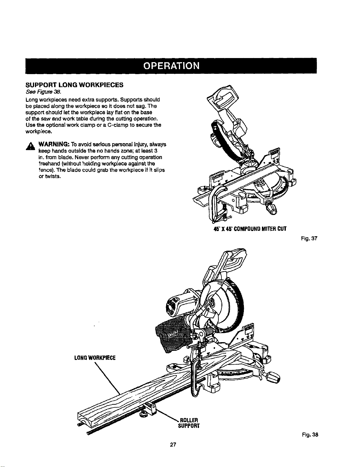
SUPPORT LONG WORKPIECES
See Figure38.
Longworkpieces need extrasupports.Supportsshould
be placedalongthe workpiece so itdoes not sag. The
supportshouldletthe workplece layf/aton the baee
of the saw and work table dudngthe cuttingoperation.
Use theoptionalwork clamp or a C-clamp to securethe
workpiece.
_, WARNING: To avoid seriouspersonalinjury,always
keep handsoutsidethe no handszone;at least3
in,from blade. Never performany cuttingoperation
fraehand(withoutholding workplece againstthe
fence), "Theblade coutdgrabthewor_piece_fit stips
or twists.
4,5"X48"COMPOUNDMITERCUT
Fig. 37
LONGWORKPIECE
27
ROLLER
SUPPORT
Fig. 38

CUTrlNG COMPOUNDMITERS
To aid inmakingthe correct se_ngs, the compoundangle se_ng chart belowhas been provided.Sincecompoundcuts
are the mo_t difficutt to accuratetyobtain,trfatcuts shourdbe made inscrap materiat, and much thoughtand ptanning
made, priorto makingyourrequiredcut.
NUM-"-L., ,Jr o,_=,=
PITCH
ol=slo 4 I 5 6 I 7 I 8 I 9 I 10
o" M- .oo° M- oo" M-3000"I M-25,71"M-22.50"M-20,00"U-18,00=
B- 0.00= B- 0,00° B-0.00 = B- 0.00° B-0.00 ° B- 0.00° B- 0.00=:
5" M-44"89= M'35"90= M-29'gl= M-25'63° M-22"42= M'19"93° M'17"94=
B- 3.53" B- 2.94" iB- 2.50" B- 2,17= B- 1.91° B- 1.71° B- 1.54=
10° M-44-56 ° M-35.58 ° M-29,62°i M-25,37 ° M-22.19 ° M-19.72 ° M-17.74 °
B- 7,05° B- 5.86" B- 4.98" B- 4.32° B- 3.81° B- 3.40° B- 3.08=
M-44.01 ° M-35,06 ° M-29.15 ° M-24.95 = M-21.81 ° M-19.37 = M-17.42 =
15°
B-10.55" B- 8,75° B- 7.44° B- 6.45" B- 5.68" B- 5.08° B- 4.59"
20° M- 43.22" M- 34,32° M- 28.48° M- 24.35° M- 21.27° M- 18.88" M- 16.98°
B-14.00 ° B-11.60 ° B- 9.85= B- 8.53° B- 7,52" B- 6.72" B- 6.07°
25° M-42.19 ° M-33,36 ° M-27.62 ° M-23.56 ° M-20.58 ° M- 18.26° M- 16.41°
B- 17.39" B- 14.38° B- 12.20° B- 10.57° B- 9.31° B- 8.31" B- 7.50"
30° M-40-89°IM-32,18 ° M-26.57 ° M-22.64 ° M-19.73° M-17.50 " M-15.72 °
B- 20.70° B- 17.09° B- 14.48° B- 12.53° B- 11.03° B- 9.85° B- 8.89°
35° M-39.32 ° M-30.76 ° M-25.31 ° M-21.53 = M-18.74 ° M-16.60 = M-14.90 °
B-23.93 = B- 19,70° B- 16.67" B- 14.41° B- 12.68= B- 1!.31° B- 10.21°
40° M-37.45 ° M-29.10 ° M-23,86 = Vl-20,25 ° M-17.80 ° M-15,58 ° M-13.98 =
B-27.03" B-22.20 = B-18.75" B- 16,19= B- 14.24° B-12.70 ° B-11.46 °
45° M-35-26° M-27.19 ° M-22,21 ° M-18.80 ° M-16.32 ° M-14,43 ° M-12.94 °
B- 30.00" B-24,56" B-20.70 ° =L-17,87" B- 15,70° B- 14.00° B- 12,62"
iM-32.73 ° M-25,03" M-20,36 ° M-17.20 ° M-14.91 ° M-13.17 ° M-11.80 °
50° B-32_80° B-26.76 = B- 22.52° B- 19.41= B- 17.05" B- 15.19= B- 13.69°
55= M-29.84 ° M-22.62 ° M-18,32 ° M-15.44 ° M-13.36 ° M-11,79 ° M-10.56 °
B- 35,40" B-28,78 ° B-24.18 ° B- 20,82° B- 18,27" B- 16.27° B- 14.66°
M-26.57 = M-19.96 ° M-16.10 ° M-13.54 =! M-11.70 ° M-10.31 ° M- 9.23°
60°
B- 37,76° B-30,60" 13-25,66° B- 22,07° E3-19.35" B-17.23" B- 15.52°
M-22.91 = M-17.07 ° M-13,71 ° M-11.50 = M- 9.93° M- 8.74=; M- 7.82°
65° B-39.86" B'32.19 ° 8-26,95 ° 18-23.16" B-20.29 ° B-18.06 ° 8-16.26 °
M-18-88 ° M-13.95 ° M'11.17 ° M- 9,35° M- 8.06° M- 7.10= M- 6.34°
70°
B-41.64 ° B-33.53 ° B-28.02" B-24.06" B-21.08 = B-18.75 ° B-16.88 °
75= M-14.51 ° M-10.65 ° M- 8.50° M- 7.10° M- 6.12° M- 5.38° M- 4.81=
B-43.08 ° B-34.59 ° B-28.88" B-24,78 ° B-21.69 ° B-19.29 = B-17.37 °
80° M- 9.85= M- 7.19° M- 5.73° M- 4.78° M- 4.11= M- 3.62° M- 3.23"
B- 44.14" B-35.37 = B-29,50 ° B-25,30 = B- 22.14" B- 19.68° B- 17.72"
M- 4.98° M- 3.62° M- 2.88° M- 2.40° M-2.07 = M-1,92 ° M- 1.62°
85° B- 44,78= B-35.84" B-29.87 ° B-25.61" B-22.41 ° B- 19.92" B- 17.93°
90° M- O.00= M- 0,00° M- 0.00° M- 0.go" M- 0,DO° M- 0.00° M- 0,00°
B-45,00" B-38.00 ° B-30.00 = B-25.71 ° B-22.50 ° B-20.00 ° B- 18,00"
Each B (Bevel)and M [Miter)SettingIs Giventothe Closest0.005=.
COMPOUND-ANGLE SETTINGS FOR POPULAR STRUCTURES
28
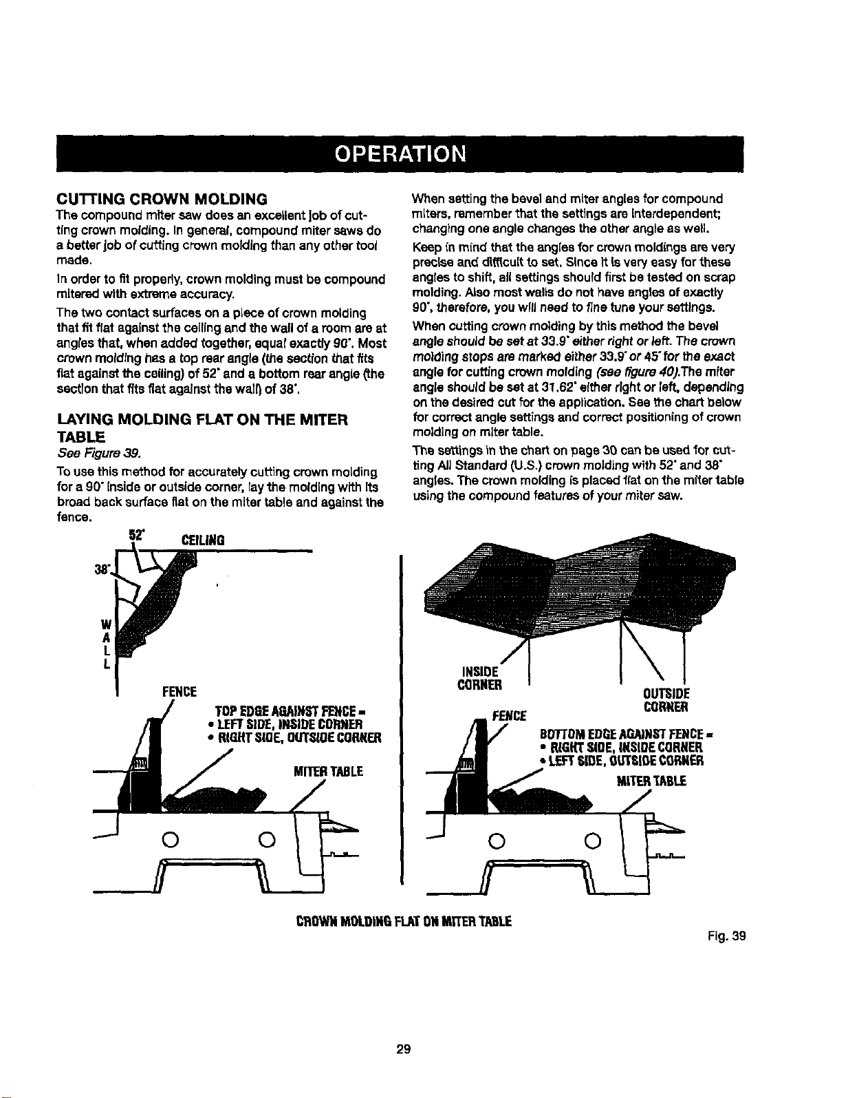
CU'I'I'ING CROWN MOLDING
The compoundmiter sew does an excellentJobofcut-
tingcrownmolding.In general, compound miter eaws do
a better Jobof cuffingcrownmoldingthan any othertool
made,
In orderto fit properly,crownmoldingmust becompound
mltaredwith extremeaccuracy,
The two contactsurfaces on a piece of crownmolding
thatfit flat against the ceilingand thewall of a roomare at
anglesthat, when added together,squatexactlyg0".Most
crownmoldinghasa top rearangle (_e section_at fits
fiat againstthe ceiling}of 52"and a bottom rearangle(the
sectionthat fitsfiat against the wail}of 38",
LAYING MOLDING FLAT ON THE MITER
TABLE
See F'tgure39,
Tousethis method for accuratelycuttingcrownmolding
for a 90" insideor outside comer,raythe molding with Its
broad back surfaceflat on themiter table and againstthe
fence.
62" CEILING
w
A
L
L
FENCE
TOPEDGEAGAINSTFENCE-
• LEFTSIDE,INSIDECORNER
• RIGHTSLOE,OUTSIOECORNER
MITERTABLE
© 0
When settingthe beveland miter angles for compound
miters, rememberthat thesettingsare interdependent;
changingone anglechangestheotherangleas well.
Keep inmind that theangles forcrownmoldingsare very
preciseand dl_cult toset. Since itisveryeasy forthese
anglesto shift,all settingsshouldfirstbe testedon scrap
molding. Alsomostwaftsdo nothaveanglesofexactly
90",_erefore, youwlflneed to finetune yoursettings.
When cuttingcrownmoldingbythismethod the bevel
angle shouJdbe set at 33.9"eitherrightor left. The crown
molding stops aremarke_ either33.9"or 45"fortheexact
angle forcuffingcrownmolding (see _gure 40).The miter
angle shouldbe set at 31.62"eitherrightor left, depending
on thedesirecicut forthe applieation.See the chartbelow
for correctanglesettingsand correctpositioningofcrown
moldingon miter table.
The settingsinthe charton pegs 39 canbe used for cut-
tingAJ]Standard(U.S.)crownmolding with 52"and 38"
angles.The crownmolding is placedflaton_.hemitertable
usingthecompound features of yourmitersaw.
INSIDE
CORNER
FENCE
OUTSIDE
CORNER
BD7"I'DMEDGEAGAINSTFENCE,,
• RIGHTSIDE,[KSIDECORNER
• LEFTSLOE,OUTSIDECORNER
MITERTABLE
CROWNMOLDINGFLATONMITSRTABLE
Fig. 39
29
33.9°
Fig.40
Bevel
Angte TypeofCut
Setting
Leftside,insidecomer
33.85" 1.Topedgeofmoldingagainstfence
2.MitertablesetrJght31.62"
3.Saveleftendof cut
Right side, Inside corner
1. Bottom edge of moldingagainst fence
33.85" 2. Miter table set left31.62"
3, Save left end ofcut
Left side, outside comer
1. Bottom edge of molding against fence
_,3.65" 2. Miter table set left 31.62"
3. Save right end ofcut
Right side, outside corner
33.85" 1.Top edge of molding againstfence
2. Miter table set right 31.62"
3, Save right end of out
molding.Alsomostwalls do not haveangles ofexactly
90",therefore,you willneedto finetune yoursettings.
When cuttingcrownmolding bythismethod the bevel
angte should be set at 0".The miter angloshouldbe set at
45"eitherrightor left, dopondingonthe desiredcutfor the
sppLLcation.
Usingthe markingsonthe throatplata,you canaccurately
cutAllStandard (U.S.)with 52"and 38"anglesin sizes
of 2-3/4 in.,3-5/8 in., 4-5/8 in.,and 5-1/4. Youcannot
usathe markingson the throatplatowhoncuttingcrown
moldingwith 45"and 45"angles.
• Loosenthe crownmolding stop byturningtheknob
countemlockwlse.
• Placethes_oplntheholeon e1_ertheteflorthadght
s_deof +_hesaw's _es. See figure41.
• With the bottom of themolding (wallaide)againstthe
miterfence andthe top ofthe molding(callingaide)
against the mitertable, alignwith the desiredmarkon
the throat plate thenspinthe crownmoldingstop until
itfitssnugglyagainstthecrown molding.
• Securethe crownmoldingstop inplaca by turningthe
knobclockwise.
• Holdthe crownmoldinginplace withyour hand(the
side not securedwith thestop).
NOTE: NEVER haveyour handinsidethe no hands
zonewhile the saw Is on,
• Slowty towerthe blade Intoand through the workptece,
• Releasethe switchtriggerand allowthebladeto stop
rotat'mgbefore raisingtheblade out ofworkpiace.Wait
untilthe elactflc brokestopa bladefromturningbefore
removJngtheworkplace frommitertable.
CROWNMOLDING
STOP
_._ KNOB
I
!
CUTTING MOLDING USING THE CROWN
MOLDING STOP
See Figures41 and 42.
To usethismethod for accuratelycuttingcrownmolding
for a 90"insideor outsidecorner,place the crownmolding
upsidedown on the mitertable.
Keep in mindthatthe anglesfor crownmoldingsarevery
preciseand d]fficuitto set. Since it isveryeasy forthese
engtesto shift,el!settingsshoutdfirstbe tested on scrap
3O
Fig. 41
MARIOHGSOH
THROATPLATE
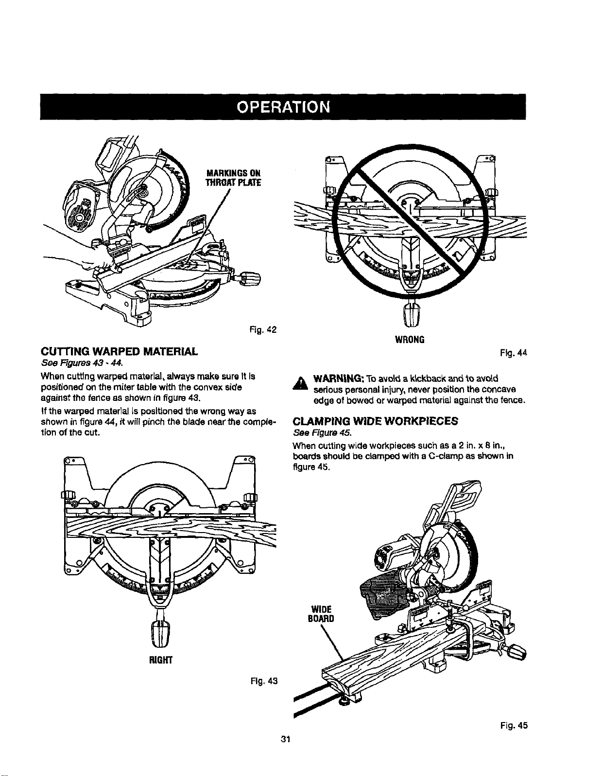
CUTTING WARPED MATERIAL
See Figures43 - 44.
When cuttingwarped material,always make sureIt Is
positionedon the mitertable with the convexside
againstthe fence as shownin f_gure43.
If thewarped matedal Is positionedthewrong way as
shownin f_gum44, itwillpinch the bladenear the comple-
tionof thecut.
RIGHT
Fig. 43
WRONG
Fig.44
,_ WARN,|NG: To avoid a k_c_d_ack_d to avoid
seriouspersonaliniury,never positiontheconcave
edge of bowed or warped material agaLnstthe fence.
CLAMPING WIDE WORKPIECES
see Figure45.
When cuttingwLcleworkpieces suchas a 2 in.x 8 in.,
boardsshouldbe clampedwith a C-clamp as shownin
figure 45.
WIDE
BOARD
Fig. 45
31
_, WARNING: Before performingany adjustment,
make surethe tool Isunpluggedfromthe power
supplyand the switchis in the OFF ( O ) position,
Failureto heed thiswarningcould resultin serious
personalInfury.
The compoundmiter saw has been adjustedat the fac-
toryfor makingveryaccuratecuts. However,someofthe
componentsmight havemoved out ofalIgnmentduring
shlpplng,AJso,over a periodof time, readjustmentwrit
probablybecome necessarydue to wear.After unpacking
the saw,checkthe following adjustments beforeyou
beginusingsaw, Make any readjust_ants thatare
necessaryand per_odic_l_checkthe parts alignment
to make surethat the saw iscuffingaccurately.
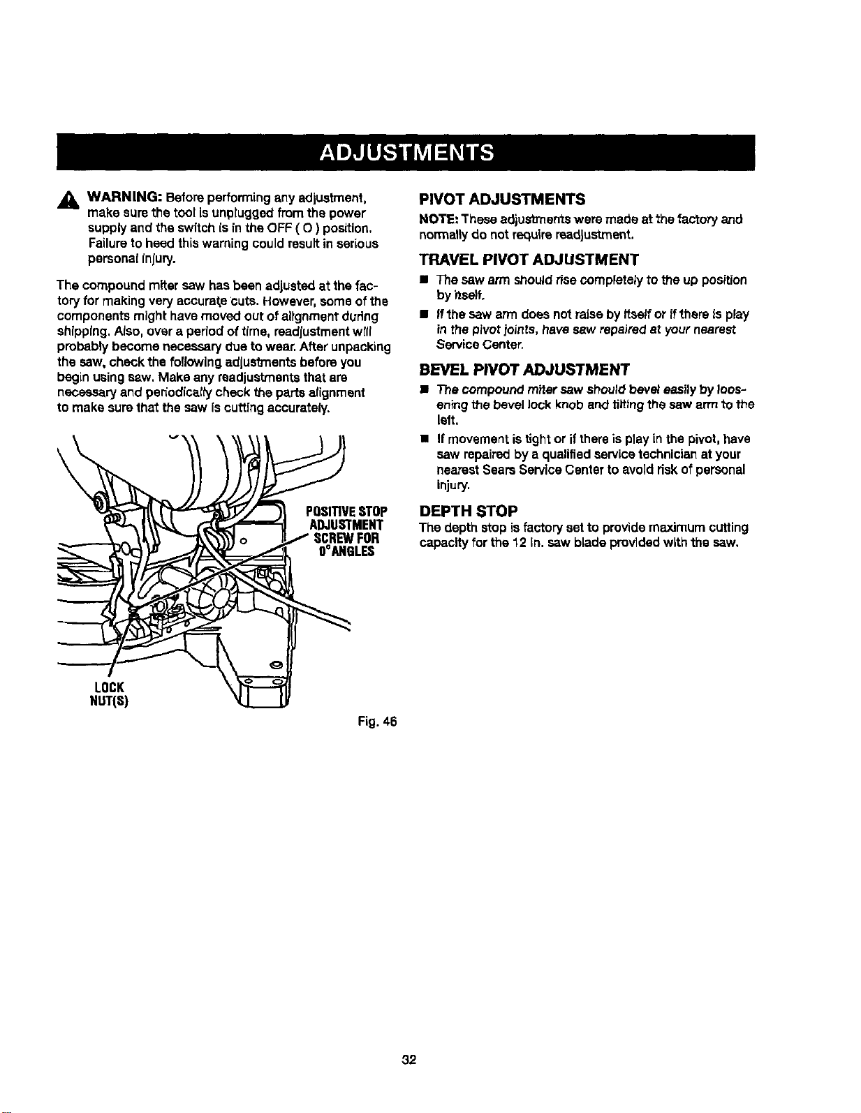
\
POSITIVESTOP
ADJUSTMENT
SCREWFOR
OOAHBLES
PIVOT ADJUSTMENTS
NOTE: These edjusb'nerrtswere made at the factory and
normal_Jdo not requirereadjustment.
TRAVEL PIVOT ADJUSTMENT
• The saw arm shouldrisecompletelyto the up position
by itself.
• If the saw arm does not raiseby Itselfor if there Is play
inthe pivot.ioints,havesew repairedat yournearest
ServiceCenter.
BEVEL PIVOT ADJUSTMENT
• The compound mitersaw shouldbeveJeasilybyloos-
eningthe bevel lock knoband tiltingthe saw arm to the
left,
• If movementis tightor if thereisplay in the pivot,have
saw repairedbya qualifiedservice technicianat your
nearestSearsService Centerto avoid dskof personal
injury,
DEPTH STOP
The depthstop isfactoryset to providemaximum cutting
capacity forthe 12 In. saw bladeprovidedwith the saw,
LOCK
NUT(S)
Fig. 46
32
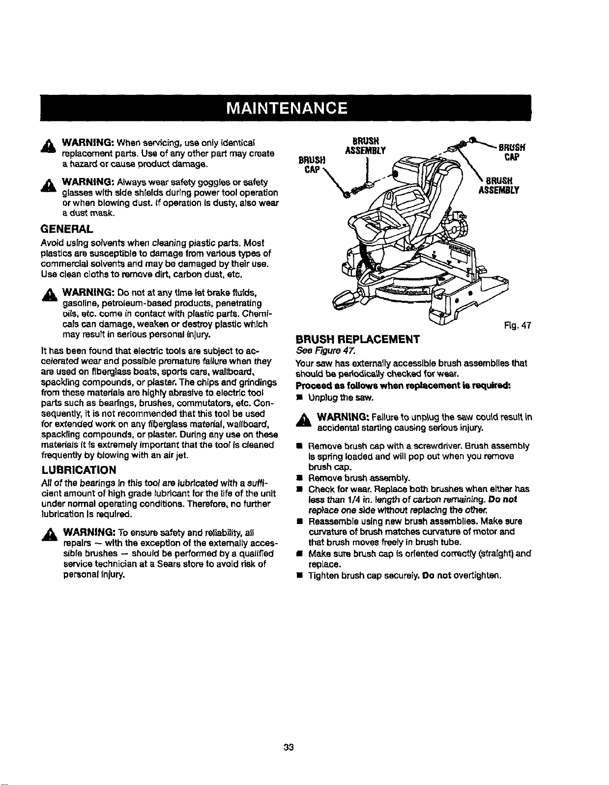
,i_ WARNING: When serv!oing, use onlyidentical
replacementpar_e.Useof any otherpart may create
a hazard or causeproductdamage.
_1_ WARNING: Alwayswear cataty gogglesor safety
glasseswith sideshieldsdurlngpowertool operation
or when blowing dust. If operation is dusty, also wear
a dust mask.
GENERAL
Avoidusingsolventswhen cleaningptasticparts.Most
plasticsare susceptibleto damage fromvedoustypesof
commercialsolventsand may be damaged bytheiruse.
Useclean clothsto removedirt, carbondust, etc.
,_L WARNING: Do not at any time letbrake f_ulds,
gasoline,petroleum-basedproducts,penetrating
oils.etc. come in contactwRh plasticparts.Chemi-
calscan damage, weaken or destroyplasticwhich
may resuRin seriouspersonalinjury.
It hasbeen found that elecb'ictoolsaresubjectto ac-
celeratedwear and possibleprematurefailurewhen they
are usedon fiberglassboats,sportscars, wallboard,
spacklingcompounds,or piaster.The chipsand gdndings
from thesematerials are highlyabrasiveto electrictool
partssuchas bearfngs,brushes,commutators,etc. Con-
sequently,it isnot recommendedthat this toolbe used
for extendedwork on anyfiberglass material,wallboard,
specklingcompounds,or piaster.Duringany useon these
matedais it [s extrsmely importantthat thetool iscleaned
frequentlyby blowingwith an air jet.
LUBRICATION
All ofthe bearingsIn this toolare lubricatedwith a suffi-
cient amount ot highgrade lubricantfor the life ofthe unit
under normaloperatingconditions.Therefore,no further
lubricationIs required.
,_ WARNING: To ensure safetyand reliability, ale
repairs -- with theexception of the externally acces-
sibrebrushes -- shouldbeperformedby a qualified
servicetechnicianat a Sears storeto avoidriskof
personalinlury.
DRUSFI
FLg,47
BRUSH REPLACEMENT
See Figure47,
Yoursaw hasexternally accessible brushassembliesthat
shouldbe periodicallychecked forwear.
Proceed as follow,, when replacement is required:
• Unplugthe saw,
,_ WARN|NG: Falturato un_iug the saw couldresultin
accidentalstartingcausing seriousinjury.
• Remove brushcapwith a screwdriver.Brush assembly
Is springloadedand will popout when youremove
brushcap.
• Remove brush assembly.
• Check forwear. Replaceboth brusheswhen eitherhas
less than 1/4 in._engthof ca,,bonremaining.Do not
replaceone sidewithoutreplacingthe other,
• Reassembleusingnew brushassemblies.Make sure
curvatureof brushm_tchas curvatureofmotorand
that brushmovesfreely in brushtube.
• Make sure brush cap is odentedcorrectly(straight}and
repLace.
• "13ghtenbrushcap sscursly.Do not overtighten.
33
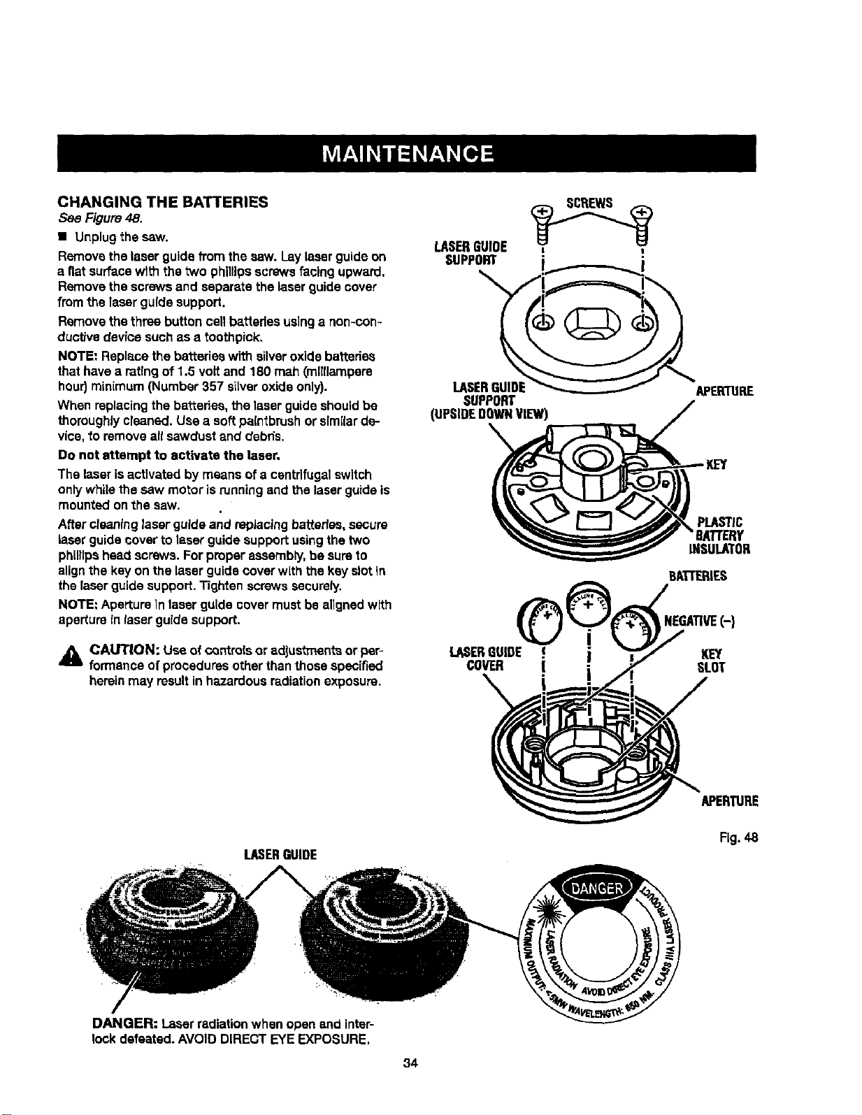
CHANGINGTHEBATTERIES
See Figure48.
• Unplugthe saw.
Removethe laser guidefrom the saw. Laylaserguideon
a flatsurfacewlth the two phillipsscrewsfacing upward.
Removethe screwsand separatethe laser guidecover
fromthe laser guide support.
Removethe three button cellbatteriesusinga non-con-
ductivedevice such as a toothpick.
NOTE: Replacethe batterieswith silveroxidebatteries
thathave a ratingof 1.5 voltand 180 mah (milliampere
hour)minimum (Number 357 silveroxideonly).
When replacingthe batteries,the laser guideshouldbe
thoroughlycleaned. Use a softpaintbrushor srmilarde-
vice, to removeall sawdustand debds.
Do not attempt to activate the laser,
The laser isactivated by meansofa centrifugalswitch
onlywhilethe saw motor isrunningend the laserguide is
mounted onthe saw.
After cleaninglaserguide and replacingbatteries,secure
laserguide coverto laserguide supportusingthe two
phillipshead screws, Forproperassembly,be sureto
alignthe key on the laserguide coverwith the key slotin
the laserguide support.Tightenscrewssecurely.
NOTE: ApertureIn laser guide covermustbe aligned with
aperture inlaser guide supDort.
_i CAUTION: Useof c_ntrolsor adjustments or pep
formance of proceduresotherthanthose spec[fied
herein may result in hazardous radiation exposure.
LASERGUIDE ,_'_I
SUPPORT
LASERGUIDE APERTURE
SUPPORT
(UPSIDEDOWNVIEW)
PLASTIC
'8ATrERY
INSULATOR
BA'L-rERIES
NEGATIVE(-}
LASERGUIDE € KEY
COVER [ SLOT
APERTURE
LASERGUIDE
Fig.48
DANGER: Laser radiationwhen open and inter-
lock defeated. AVOID DIRECTEYE EXPOSURE.
34
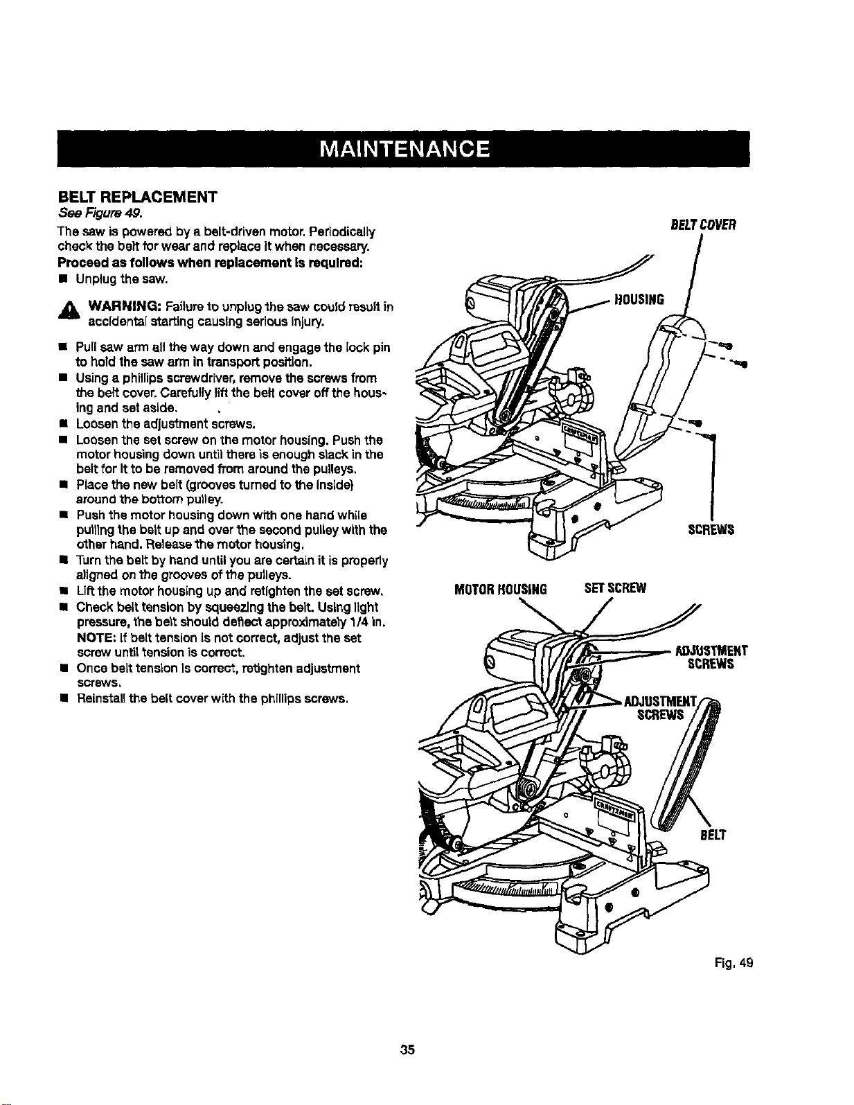
BELT REPLACEMENT
Sea Figure4,9.
The sew is powered by a belt-drivenmotor.Periodioatly
checkthe belt for wearand replaceitwhen nscessery.
Proceed as follows when replacement Is required:
• Unplugthe saw.
_IL WARNING: Failureto unplugthe sew couldresultin
accidentalstartingcausingseriousInjury.
• Pullsaw arm all theway downand engagethe lock pin
to hold thesew armin transportposition,
• Usinga phillipsscrewdriver,remove thescrewsfrom
the belt cover.Carefullylift the belt coveroffthe hous-
ing and set aside.
• Loosenthe adjustment screws.
• Loosenthe set screwon the motorhousing,Pushthe
mot_r housing down unt'_lthere "LsenoughstackInthe
beltfor It to be removedfrom aroundthe pulleys,
• Placethe new belt (groovesturnedto the Inside)
arouncithe bo'_ompul)ey.
• Pushthe motorhousingdownwith one handwhile
pulllngthebert up and overfne secondpulleywith the
otherhand. Releasethemotor housing.
• Turnthe belt by handuntilyou are certainit isproperly
a)ignedonthe groovesofthe pulleys.
• Liftthe motorhousingup and retightenthe set screw,
• Check belttensionby squeezingthe belt. Usinglight
pressure,thebeatshoutdde_ect approximately1/4 in.
NOTE=If belttension isnot correct, adjustthe set
screwuntiltension is correct.
• Once belttensionIs correct,retightenadjustment
scr_s,
I Reinstall the belt cover with the phillips screws.
MOTORHOUSING
SETSCREW
BELTCOVER
Fig. 49
35

36
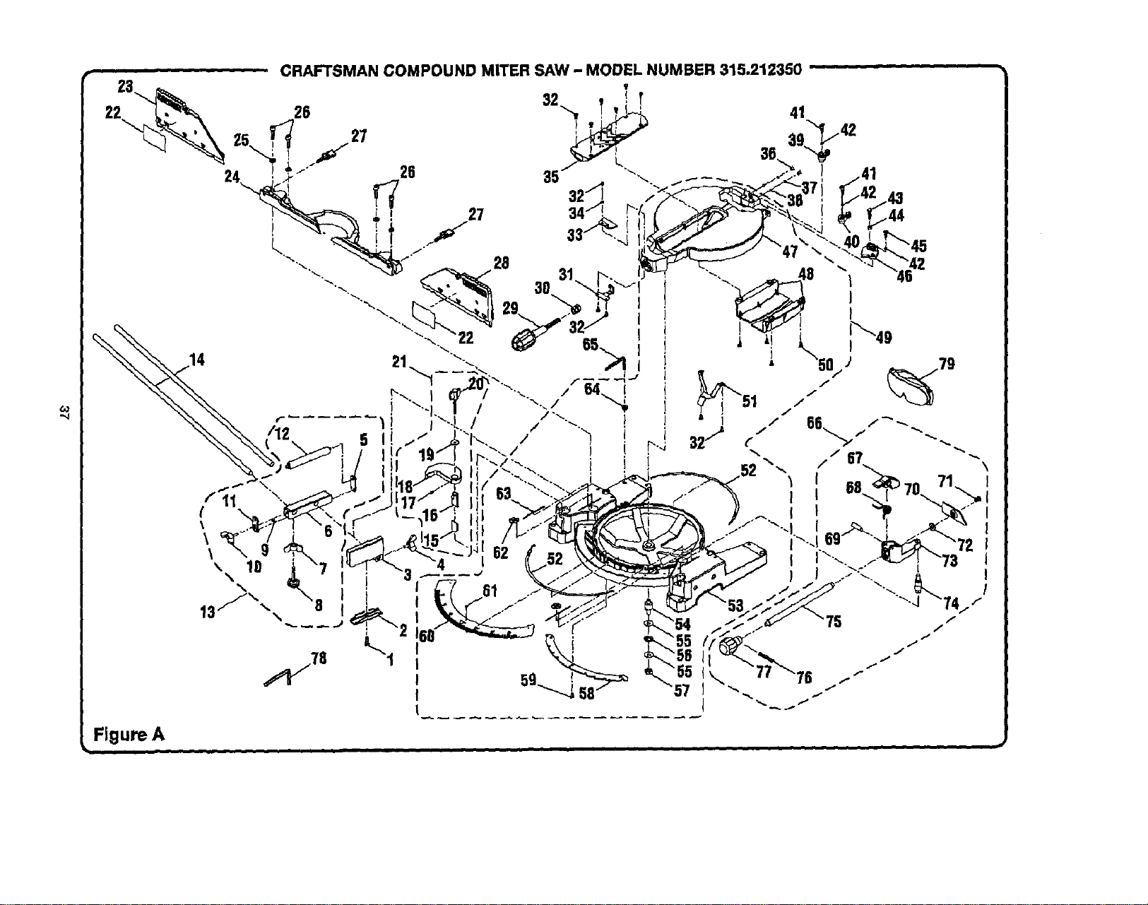
,,,j
Figure A
CRAFTSMAN COMPOUND MITER SAW - MODEL NUMBER 315.212350
3O

CRAFTSMANCOMPOUNDMITERSAW- MODELNUMBER315.212350....
The model numberwillbe foundon a plateattachedto themotorhousing.Alwaysmention the modelnumberinallcorrespondenceregardingyour |MITER SAW or when orderingrepairparts.
I
oo
_o
KEY PART
NO. NUMBER
1 555516000
2 558511100
3 558507200
4 558512100
5 545506000
6 545507000
7 A33055056000
8 5455090O0
9 A10003040050
10 545511000
11 545505000
12 545508000
13 545A07030
14 545512000
15 565506000
16 565505000
17 A18003040080
18 565504000
19 A35010823020
20 565507000
PARTS LIST FOR FIGURE A
KEY PART
DESCRIPTION QTY. NO. NUMBER
*Wing Nut (M8 x 30 ram)................................... 1
ClampBracket................................................. 1
Stop Block....................................................... 1
* Wing Screw(1/4-20 x 12 ram).........................1
RollerSupport FrontBrace.............................. 1
RollerSupport Base........................................ 1
* Wing Nut (5/16 in.)**STD541631 .................... 1
LevelingScrew(5/18 in.)................................. 1
* Screw(M4 x 5 mm PanHd._............................ 4
*Wing Screw (MSx 20 ram) .............................. 1
Roller SupportEnd Brace................................ 1
Roller ............................................................... 1
Roller SupportAssembly
(IncludesKey Nos. 5-12) ................................. 1
Table Ex'tenslon............................................... 2
Lower Tube, Adjustable ................................... 1
Upper Tube, Adjustable ................................... 1
* Set Screw (M4x 8 ram)................................... 1
CrownMolding Clamp .....................................1
FlatWasher (MSx 23 x 2t)............................... 1
Crown Molding Knob ....................................... 1
21 565A07020
22 511113000
23 56511200O
24 565116000
25 A36030814204
26 A07103080200
27 565123000
28 565111000
29 565117000
30 558111109
31 565110000
32 A10003050100
33 565113000
34 A35030501010
35 565106000
36 565119000
37 565120000
38 A59000006000
39 565122000
40 565121000
41 565118000
DESCRIPTION QTY.
Crown Molding_gtopAssembly
(IncludesKeyNos. 15-20) ...............................1
SlidingMiterFence Label................................2
SlidingMiterFence (left)..................................1
Fence............................................................... 1
* LockWasher(M8) **STD852008 .....................4
* Bolt(M8 x 20 mm Soc. Hd.)............................4
FenceScrew.................................................... 2
SlidingMiterFence (right)................................1
Miter Lock Handle ........................................... 1
ClampNut ....................................................... 1
Fixed Plate....................................................... 1
* Screw (MSx 10 mm Pan Hd.)..........................6
Miter Indicator ................................................. 1
RatWasher(M5 x 10 xl t)................................ 1
Throat Plete ..................................................... 1
Set Screw ........................................................ 2
Look Spring..................................................... 2
Ball...................................................................2
Bevel Stop (left) ...............................................1
Bevel Stop(right)............................................. 1
* Screw(M6 x 6 ram)..........................................2
* Standard Hardware Item -- May Be Purchased Locally
** Available From DIv,98 -- Source 980.00
*_' Available At Your Nearest Sears Catalog Order or Retail Store
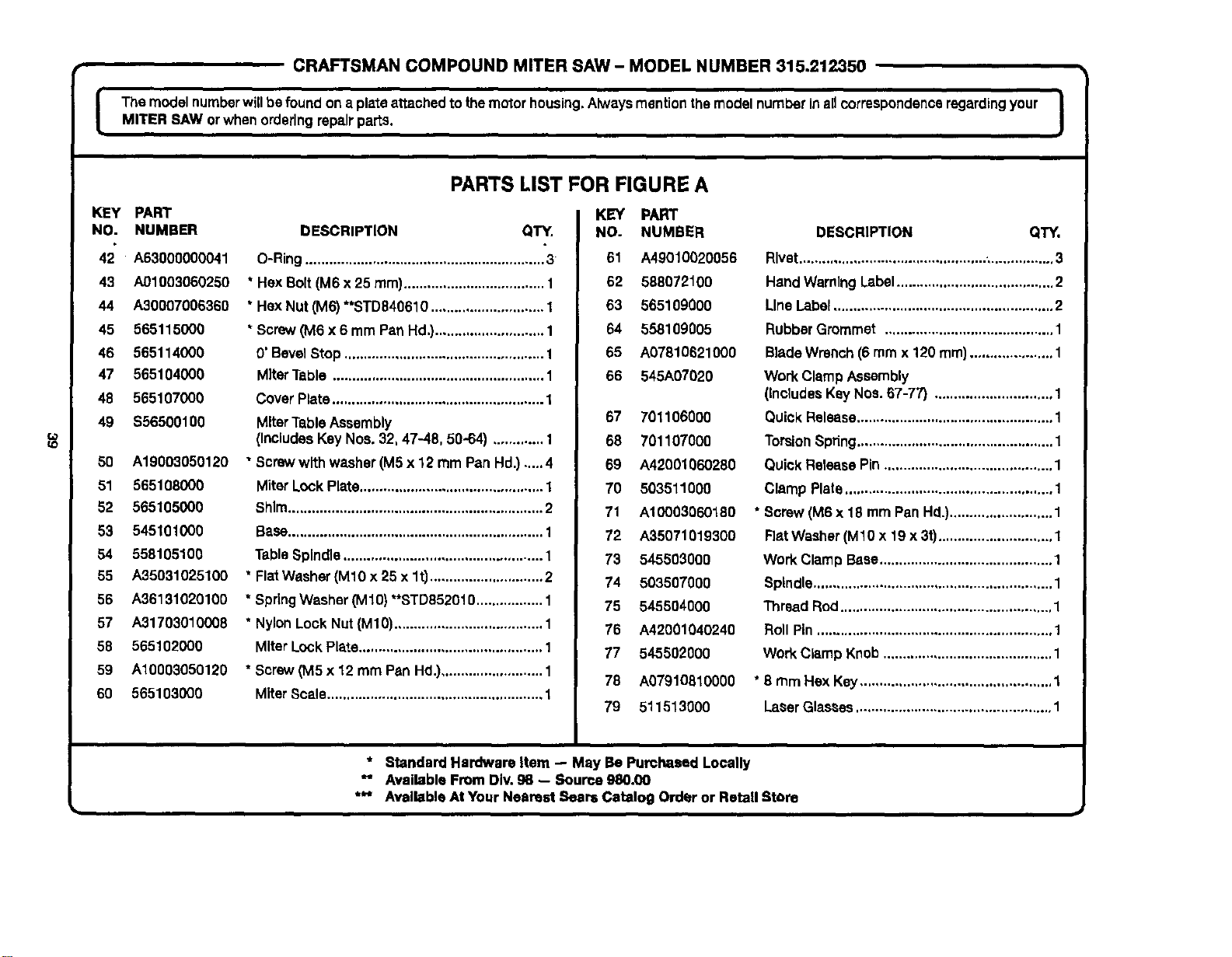
• CRAFTSMAN COMPOUND MITER SAW - MODEL NUMBER 315.212350
I The model numberwillbefoundon a plateattachedtothemotorhousing,AlwaysmentionthemodelnumberinaUcorrespondenceregardingyour |
MITER SAW orwhenorderingrepairparts.
I
KEy PART
NO. NUMBER
42 A63000000041
43 A01003060250
44 A30007006360
45 565115000
46 565114000
47 565104000
48 565107000
49 $56500100
50 A19003050120
51 565108000
52 565105000
53 545101000
54 558105100
55 A35031025100
56 A36131020100
67 A31703010008
58 565102000
59 A10003050120
60 565103000
PARTS LIST FOR FIGURE A
DESCRIPTION QTY.
O-Ring............................................................. 3
* Hex Bolt(M6x 25 ram).................................... 1
• HexNut (M6) **STD840610.............................1
* Screw(M6 x 6 mm PanHd,}............................1
0' BevelStop ................................................... 1
MiterTable ...................................................... 1
CoverPlate...................................................... 1
MiterTableAssembly
(IncludesKeyNos.32, 47-48, 50-64) .............1
"Screw with washer (M5x 12 mm Pan Hd.)....,4
MiterLockPlate............................................... 1
Shim................................................................. 2
Base................................................................. 1
TableSpindle................................................... 1
* FlatWasher(M10 x 25 x lt) .............................2
* SpringWasher(M10)"*STD852010................. 1
* NylonLock Nut(M10)...................................... 1
MiterLockPlate............................................... 1
* Screw(M5 x 12 mm PanHd.).......................... 1
MiterScale....................................................... 1
KEY PART
NO. NUMBER
61 A49010020056
62 58807210O
63 565109000
64 558109005
65 A07610621000
66 545A07020
57 701106000
68 701107000
69 A42001060280
70 503511000
71 A10003060180
72 A35071019300
73 545503000
74 503507000
75 545504000
76 A42001040240
77 545502000
78 A07910310000
79 511513000
DESCRIPTION QTY.
Rivet................................................,................3
HandWarningLabel........................................ 2
LineLabel........................................................ 2
RubberGrommet ...........................................1
BladeWrench (6 mmx 120 ram)..................... 1
Work ClampAssembly
(Includes Key Nos. 67-77) .............................. 1
QuickRelease..................................................1
Torsion Spring..................................................1
Quick Release Pin ........................................... 1
Clamp Plate..................................................... 1
* Sorew (M6 x 18 mm Pan Hd.).......................... 1
Flat Washer (M10 x 19 x 3t)............................. 1
Work ClampBase............................................ 1
Spindle............................................................. 1
Thread Rod...................................................... 1
Roll Pin ............................................................ 1
Work Clamp Knob...........................................1
* 6 turn Hex Key.................................................1
LaserGlasses.................................................. 1
* Standard Hardware Item -- May Be Purchased Locally
_' Available From DIv.g8 -- Source 980.00
*** Available AtYour Nearest Sears Catalog Order or Retail Storo
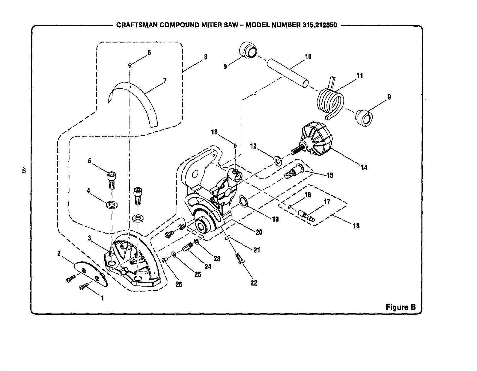
CRAFTSMAN COMPOUND MITER SAW - MODEL NUMBER 315.212350
C_
7
5
I
\
26
1
13
11
23
24
9
Figure B
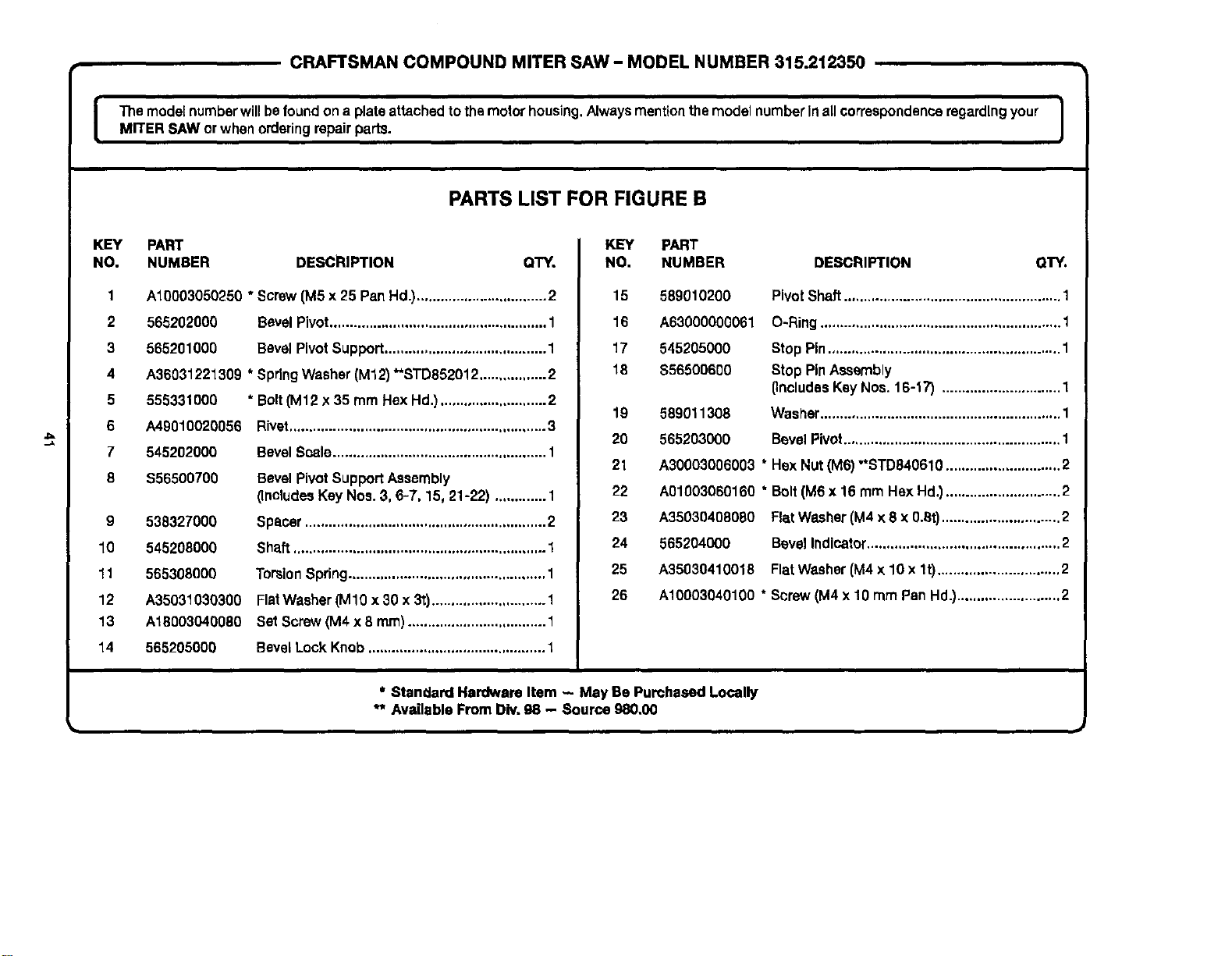
CRAFTSMAN COMPOUND MITER SAW - MODEL NUMBER 315.212350
The modelnumberwJllbe foundona plateattachedtothemotorhousing.Alwaysmentton themodelnumberInall correspondenceregardingyour I
MITER SAW or whenorderingrepairparts.
I
PARTS LIST FOR FIGURE B
KEY PART
NO. NUMBER DESCRIPTION QTY.
1
2
3
4
5
6
7
8
A10003050250 * Screw[MSx 25 PanHd.).................................2
565202000 BevelPivot....................................................... 1
565201000 Bevel PivotSupport......................................... 1
A36031221309 * SpringWasher(M12)**STD852012.................2
555331000
A49010020056
545202000
$56500700
9 538327000
10 545208000
11 565308000
12 A35031030300
13 A18003040080
14 565205000
* Bolt(M12 x 35 mm HexHd.)...........................2
Bivat .................................. ,................... .....,...3
BevelScale...................................................... 1
Bevel PivotSupportAssembly
(IncludesKeyNos.3, 6-7, 15, 21-22) .............1
Spacer............................................................. 2
Shaft................................................................ 1
TorsionSpring.................................................. 1
FlatWasher(M10 x 30 x 3t)............................. 1
Set Screw(M4 x 8 ram)................................... 1
BevelLock Knob............................................. 1
KEY PART
NO. NUMBER DESCRIPTION OTY.
15 589010200
16 A63000000061
17 545205000
18 $56500600
589011308
565203000
PivotShaft....................................................... 1
O-Ring............................................................. 1
Stop Pin........................................................... 1
Stop PinAssembly
(IncludesKeyNos. 16-17) .............................. 1
Was_er............................................................. 1
BevelPivot....................................................... 1
19
20
21 A30003006003 * Hex Nut(M6) "*STD840610.............................2
22 A01003060160 * Bolt(M6x 16 mm HaxHd.).............................2
23 A35030408080 FlatWasher(M4 x 8 x 0.6t).............................. 2
24 565204000 BevelIndicator................................................. 2
25 A35030410018 FlatWasher(M4x 10 x lt) ............................... 2
26 A10003040100 * Screw(M4x 10 rnmPan Hd.).......................... 2
* Standard Hardware Item - May Be Purchased Locally
** Available FromDiv,98 - Source 980,00
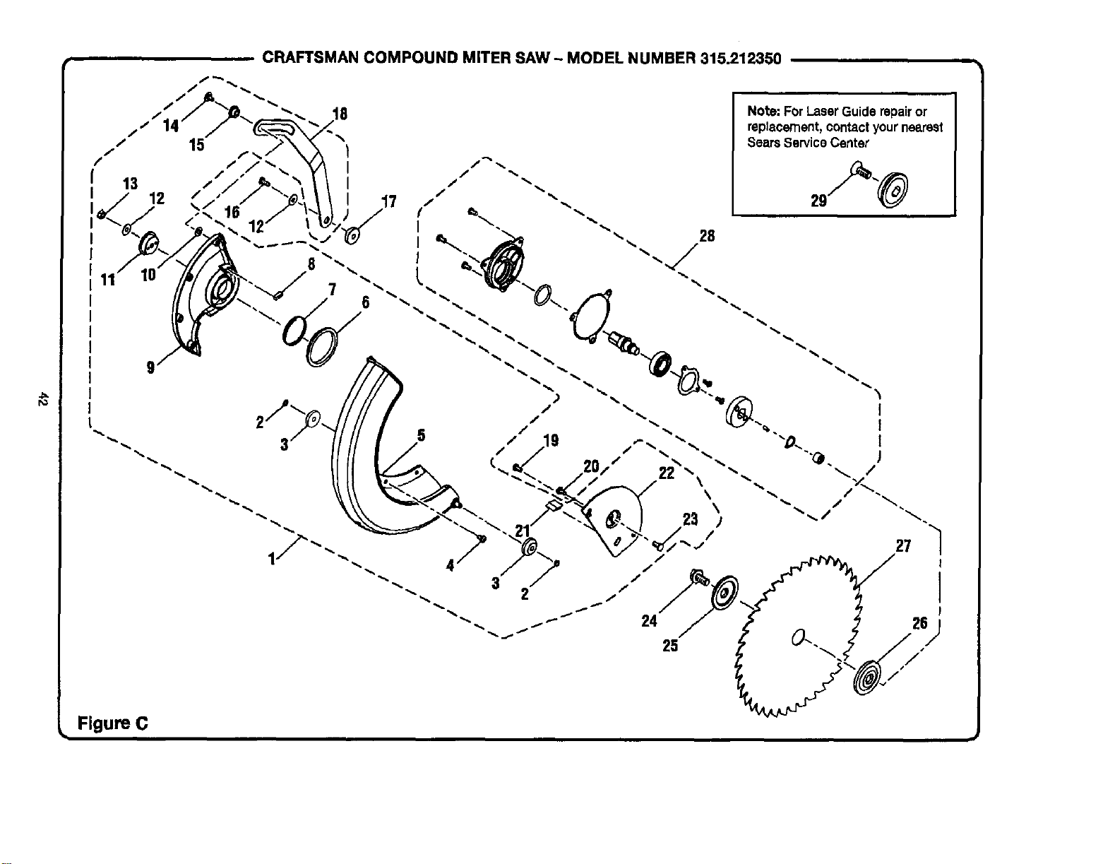
ro
CRAFTSMAN COMPOUND MITER SAW ~ MODEL NUMBER 315.212350
11
I
I
I
7
17
Note: ForLaserGuiderepairor
replacement,contactyournearest
SearsServiceCenter
Figure C

CRAFTSMAN COMPOUND MITER SAW - MODEL NUMBER 315.212350
I hemodelnumberwillbefound ona plateattachedto themotorhousing.Alwaysmentionthemodelnumberinall _orrespondence regardingyour
MITER SAW orwhen orderingrepairparts.
K_Y PART
NO. NUMBER
PARTS LIST FOR FIGURE C
$56500200
2 538417000
3 566407000
4 503402000
5 565404000
6 503413000
7 565411000
8 503414000
9 565405000
10 A35031226023
11 503407000
12 A35030616105
13
14
DESCRIPTION Q't_Y.
LowerBladeGuardAssembly
(IncludesKeyNee. 2-15, 18, 21-23)................ 1
RetainingRing................................................. 2
Roller............................................................... 2
* Screw(M5 x 8 mm PanHd.)............................4
LowerBladeGuard......................................... 1
PacJ.................................................................. 1
TensionRing.................................................... 1
Sponge............................................................ 1
LowerGuardPlate...........................................1
FlatWasher(M12 x 26 x 2l)............................. 1
Sleeve.............................................................. 1
FlatWasher(M6 x "t6x lt) .............................. 2
A31703006000 "Lock Nut (M6).................................................. 1
A10003060180 "Screw (M6 x 18 mm PanHd.)..........................1
KEY
NO.
15
16
17
18
19
2O
21
22
23
24
25
26
27
28
29
J
PART
NUMBER DESCRIPTION OTY.
558404007 Bushing............................................................ 1
A10003060185 * Screw(M6 x 18 mm PanHd.).......................... 1
565407000 Unk Bushing.................................................... 1
565408000 Link.................................................................. 1
A19001050080 * Screwwithwasher(M5 x 8 mm PanHd.) .......1
558407100
545405000
565406000
555410000
558422100
558410100
565409000
ShoulderScrew............................................... 1
Bumper............................................................ 1
BladeBoltCover............................................. 1
* Bolt(HexHd.).................................................. 1
Blade Bolt........................................................ 1
Outer BladeWasher........................................ 1
InnerBlade Washer......................................... 1
Saw Blade....................................................... 1
ArborAssembly............................................... 1
LaserGuideBolt ..............................................1
$56500300
555512000
* Standard Hardware Item - May Be Purchased Locally
*" Available From Div.98 - Soume 980,00
*** Complete Assortment Available AtYour Nearest Seers Catalog Order or Retail Store
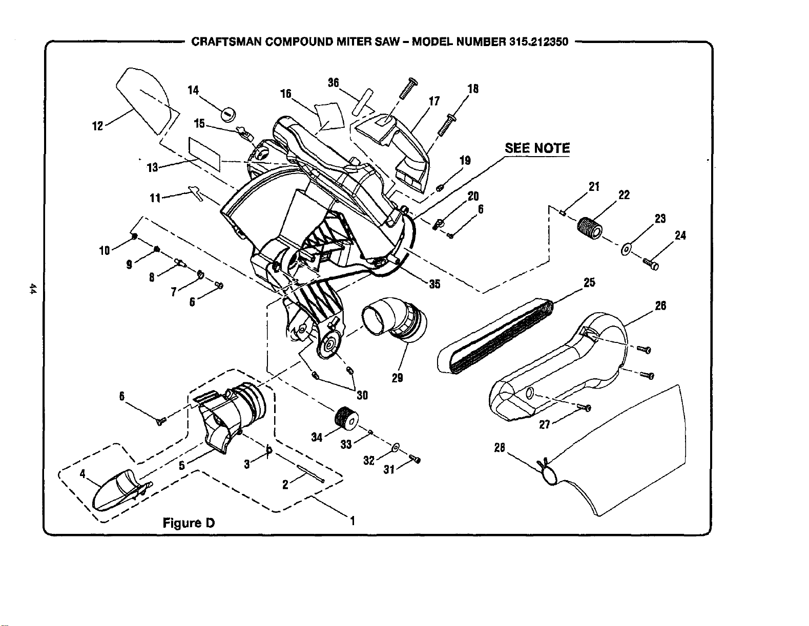
CRAFTSMAN COMPOUND MITER SAW- MODEL NUMBER 315,212350
12
36
14 16 18
\ ' 'i/
10
29
6
"-" "" Figure D
19
SEE NOTE
26
26
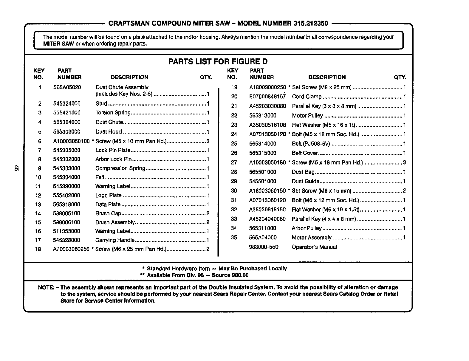
==
CRAFTSMAN COMPOUND MITER SAW- MODEL NUMBER 315.212350
J Themodelnumberwillbe foundona plataattached to themotorhousing.AlwaysmentionthemodelnumberInallcorrespondenceregardingyour IMITER SAW or whenorderingrepairparts.
I
PARTS LIST FOR FIGURE D
KEY PART KEY PART
NO, NUMBER DESCRIPTION QTY. NO. NUMBER DESCRIPTION QTY.
565A05020
545324000
555421000
565304000
565303000
Dust ChuteAssembly
(IncludesKey Nos.2-5) ................................... 1
Stud................................................................. 1
TorsionSpring.................................................. 1
DustChute....................................................... 1
Dust Hood....................................................... 1
2
3
4
5
6 A10003050100 "Screw (M5x 10 mm Pan Hd.)..........................3
7 545305000 LockPin Plate.................................................. 1
8 545302000 Arbor Lock Pin................................................. 1
9 545303000 Compression Spring........................................ 1
10 545304000 Felt................................................................... 1
11 545330000 Weming Label.................................................. 1
12 555402000 LogoPlate....................................................... 1
13 565318000 DataPlate........................................................ 1
14 588005100 BrushCap........................................................ 2
15 588006100 BrushAssembly............................................... 2
16 511353000 WarningLabel.................................................. 1
17 545328000 CarryingHandle............................................... 1
18 A70003060250 * Screw(M6 x 25 mm PanHd.)..........................2
19
2O
21
22
23
24
25
26
27
28
29
30
31
32
33
34
35
A18003080250 * Set Screw(MSx 25 ram).................................1
E07000846157 Cord Clamp..................................................... 1
A45203030080 Partial Kay(3 x 3 x 8 ram).............................. 1
565313000 MotorPulley.................................................... 1
A35030516108 FlatWasher (M5x 16 x lt) ............................... 1
A07013050120 * Bolt(M5 x 12 mm Soo.Hd.)............................ 1
565314000 Belt (PJ506-6V)................................................ 1
565315000 Belt Cover........................................................ 1
A10003050180 * Screw(M5 x 18 mm Pan Hd.).......................... 3
565501000 Dust Bag.......................................................... 1
545501000 Dust Guide....................................................... 1
A18003060150 * Set Screw(M6 x 15 ram)................................. 2
A07013060120
A35030619150
A45204040080
565311000
565A04000
983000-550
Bolt 0V16x 12 mm Soc. Hd.)............................ 1
FlatWasher(MSx 19 x 1.5t)............................ 1
PareJlelKey(4x 4 x 8 mm) .............................. 1
ArborPulley..................................................... 1
Motor Assembly.............................................. 1
Operator's Manual
* Standard Hardware Item - May Be Pumhased Locally
** Available From Div.98 -- Source 980,00
NOTE:- The assembly shown represents an important part of the Double Insulated System. To avoid the possibilityof alteration or damage
to the system, service shouldbe performed byyour nearest Sears Repair Center.Contact your nearest Sears Catalog Order or Retail
Store for Service Center Information.

Your Home
For repair-in your home-of all major brand appliances,
lawn and garden equipment, or heating and cooling systems,
rio matter who made it, no matter who sold itl
For the replacement parts, accessories and
owner's manuals that you need to do-it-yourself.
For Sears professional installaUon of home appliances
and items like garage door openers and water heaters.
1-800-4-MY-HOME ® (I-80o-469-_63)
Call anytime,dayornight(U.S.A. and Canada)
www.sears.com www.sears.ca
Our Home
For repair of carry-in items like vacuums, lawn equipment,
and electronics, call or go on-line for the IocaUon of your nearest
Sears Parts & Repair Center.
1-800-488-1222
Call anytime,dayornight(U.S.A. only)
www.sears.com
To purchase a protection agreement (U.S.A.)
or maintenance agreement (Canada) on a product serviced by Sears:
1-800-827-6655 (U.S.A.) 1-800-361-6665 (Canada)
Para pedir servicio de reparacibn
a dornicilio, y para ordenar piezas:
1-888-SU-HOGAR _
(1-888-784-6427)
Au Canada pourserviceen fran_;ais:
1-800-LE-FOYEI_ c
(1-800-533-6937)
www.saars.ca
6EAR8
zz z
® Registered Tredemm'k 1114Trademark I aMSenqlce Mark d Sears, R=_bud_ and Co.
O Marca Reglstrada / _ Marca de FI,hdca / SMMarca de SGn,'Iclo de Surs, Roebud( _ _.
McMarque de oommeroe / a_ Marque d_post_e de Sear_ Roebud_ and Co, ©Seans. Roebud_ and Co.