Dishwasher
CD.808 936 638
Installation Instructions
INSTALLER: Leave Installation Instructions with owner.
OWNER: Read your dishwasher Use and Care Manual. It contains
important safety information for operating this appliance. It also has
many suggestions for getting the best results from your dishwasher.
Read all instructions before installing dishwasher.
For your safety, please read and observe all safety
instructions. This guide will help you anticipate drain, water, and
electrical connections, and help you select the best location for the
dishwasher.
The dishwasher is provided with water heating feature.
The dishwasher is intended for connection to hot water supply.
Tip Over Hazard
Do not use dishwasher until completely installed.
Do not push down on open door.
Failure to follow this warning can result in serious
injury.
Cut Hazard
To prevent serious injury from sharp edges, wear work
gloves when handling, unpacking or disassembling unit.
Parts Included:
®
Tools and Materials Needed for
Installation (Not Included)
• Drill, Electric
• Driver, Socket 5/32", 1/4", 5/16"
• Flaring Tool/Tube Cutter (for copper tubing)
• Flashlight
• Level
• Pipe Joint Compound (for iron pipe plumbing) or
Pipe Thread Tape (for sealing threads)
• Pliers
• Safety Glasses
• Saw, Keyhole or 1/2", 11/2"to 2" Hole Cutters
• Screw Drivers, Slotted and Q2 Phillips (magnetic tip
preferred)
• Work gloves
• Tape, Electrical or Duct
• Measuring Tape
• Wire Stripper or Utility Knife
• Wrench, Hex-end
• Wrenches, 2 Adjustable (for copper tubing)
or2 Pipe wrenches (for iron pipe plumbing)
Parts You Will Need*(NotIncluded)
%
• Drain HoseClamp, 1 1/4" (3,1 cm) Diameter
• Brass Elbow, 90 ° with a 3/4" ( Q 2 cm )-11.5 NH to 3/8" ( Q 2 cm )
NPT Compression fitting
• Conduit Connector (U LListed)
• Wire Nuts, three (3) for 12-14 gauge wire (UL Listed)
•klf required:
• "Y" Branch Tailpiece and
Connector Kit (See Step 8 )
• Air Gap Kit (See Step 8 )
All the parts can be found at local hardware, electrical and
plumbing supply stores.
Electric Shock Hazard
Disconnect electrical power at the fuse box or
circuit breaker box before beginning installation.
Failure to follow this warning could result in death
or serious injury,
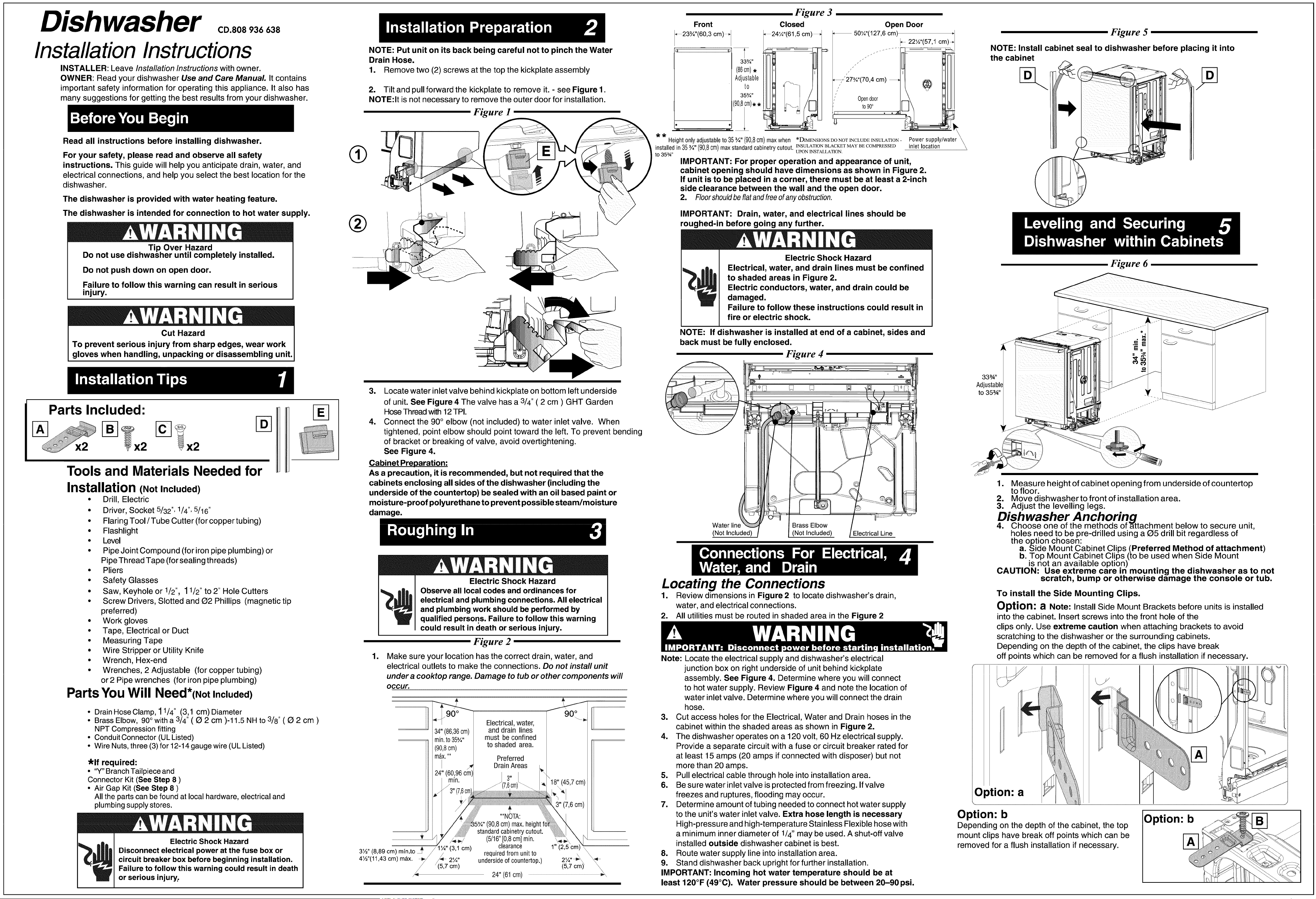
NOTE: Put unit on its back being careful not to pinch the Water
Drain Hose.
1• Remove two (2) screws at the top the kickplate assembly
2. Tilt and pull forward the kickplate to remove it. - see Figure 1.
NOTE:It is not necessary to remove the outer door for installation.
Figure 1
®
3. Locate water inlet valve behind kickplate on bottom left underside
of unit. See Figure 4 The valve has a 3/4" ( 2 cm ) GHT Garden
Hose Thread with 12TPI.
4. Connect the 90° elbow (not included) to water inlet valve. When
tightened, point elbow should point toward the left. To prevent bending
of bracket or breaking of valve, avoid overtightening.
See Figure 4.
Cabinet Preparation:
As a precaution, it is recommended, but not required that the
cabinets enclosing all sides of the dishwasher (including the
underside of the countertop) be sealed with an oil based paint or
moisture-proof polyurethane to prevent possible steam/moisture
damage.
i
Electric Shock Hazard
Observe all local codes and ordinances for
electrical and plumbing connections. All electrical
and plumbing work should be performed by
qualified persons. Failure to follow this warning
could result in death or serious injury.
Figure 2
Make sure your location has the correct drain, water, and
electrical outlets to make the connections. Do not instafl unit
under a cooktop range, Damage to tub or other components will
occur.
34"(86,36cm)
rain.to35_"
(90,8cm)
m_x.**
I
24"(60,96cm)
rain.
Electrical, water,
and drain lines
must be confined
to shaded area.
Preferred
DrainAreas
**NOTA:
(90,8cm)max.
standardcabinetrycutout.
(5/16"[0,8cm]rain.
clearance
requiredfrom unitto
undersideofcountertop.)
24" (61cm)
90° I
(45,7cm)
1" (2,5 \
(5,7 cm)
\
Figure 3
Front
_23¾"(60,3 cm)_
le q
33¾"
(86cm),
Adjustable
to
35¾"
0'8im)**
Closed
,_241A"(61,5cm)_
II
Open Door
50¼"(127,6 cm)
22½"(57,1 cm)_
7¾"(70,4 cm) @
!3
• t iocatio_Y/water_
Heightonlyadjustableto 35%" (90,8cm)maxwhen *DIMENSIONSDONOTINCLUDEINSULATION-
installedin35¾" (90,8cm)maxstandardcabinetrycutout. INSULATIONBLAC_TMAYBECOMPRESSED
UPON INSTALLATION.
to 35¾"
IMPORTANT: For proper operation and appearance of unit,
cabinet opening should have dimensions as shown in Figure 2.
If unit is to be placed in a corner, there must be at least a 2-inch
side clearance between the wall and the open door•
2. Floorshouldbeflatandfreeofanyobstruction.
IMPORTANT: Drain, water, and electrical lines should be
roughed-in before going any further.
Figure 5
NOTE: Install cabinet seal to dishwasher before placing it into
the cabinet
Electric Shock Hazard
Electrical, water, and drain lines must be confined
to shaded areas in Figure 2.
Electric conductors, water, and drain could be
damaged.
Failure to follow these instructions could result in
fire or electric shock.
NOTE: If dishwasher is installed at end of a cabinet, sides and
back must be fully enclosed.
Figure 4
33zA,,
Adjustabl
to 353A''
Figure 6
Water line Brass Elbow
(Not Included) (Not Included) Electrical Line
Locating the Connections
1. Review dimensions in Figure 2 to locate dishwasher's drain,
water, and electrical connections.
2. All utilities must be routed in shaded area in the Figure 2
Note: Locate the electrical supply and dishwasher's electrical
junction box on right underside of unit behind kickplate
assembly. See Figure 4. Determine where you will connect
to hot water supply. Review Figure 4 and note the location of
water inlet valve. Determine where you will connect the drain
hose.
3. Cut access holes for the Electrical, Water and Drain hoses in the
cabinet within the shaded areas as shown in Figure 2.
4. The dishwasher operates on a 120 volt, 60 Hz electrical supply.
Provide a separate circuit with a fuse or circuit breaker rated for
at least 15 amps (20 amps if connected with disposer) but not
more than 20 amps.
5. Pull electrical cable through hole into installation area.
6. Be sure water inlet valve is protected from freezing. If valve
freezes and ruptures, flooding may occur.
7. Determine amount of tubing needed to connect hot water supply
to the unit's water inlet valve. Extra hose length is necessary
High-pressure and high-temperature Stainless Flexible hose with
a minimum inner diameter of 1/4" may be used. A shut-off valve
installed outside dishwasher cabinet is best.
8. Route water supply line into installation area.
9. Stand dishwasher back upright for further installation.
IMPORTANT: Incoming hot water temperature should be at
least 120°F (49°O)• Water pressure should be between 20-90 psi.
1. Measure height of cabinet opening from underside of countertop
to floor.
. Move dishwasherto front of installation area.
• Adjust the levelling legs.
Dishwasher Anchoring
4. Choose one of the methods of attachment below to secure unit,
holes need to be pre-drilled using a Q5 drill bit regardless of
the option chosen:
a. Side Mount Cabinet Clips (Preferred Method of attachment)
b. Top Mount Cabinet Clips (to be used when Side Mount
is not an available option)
CAUTION: Use extreme care in mounting the dishwasher as to not
scratch, bump or otherwise damage the console or tub.
To install the Side Mounting Clips.
Option: a Note: Install Side Mount Brackets before units is installed
into the cabinet. Insert screws into the front hole of the
clips only. Use extreme caution when attaching brackets to avoid
scratching to the dishwasher or the surrounding cabinets.
Depending on the depth of the cabinet, the clips have break
off points which can be removed for a flush installation if necessary.
Option: a
Option: b
Depending on the depth of the cabinet, the top
mount clips have break off points which can be
removed for a flush installation if necessary.
Option: b
i
i
i
i
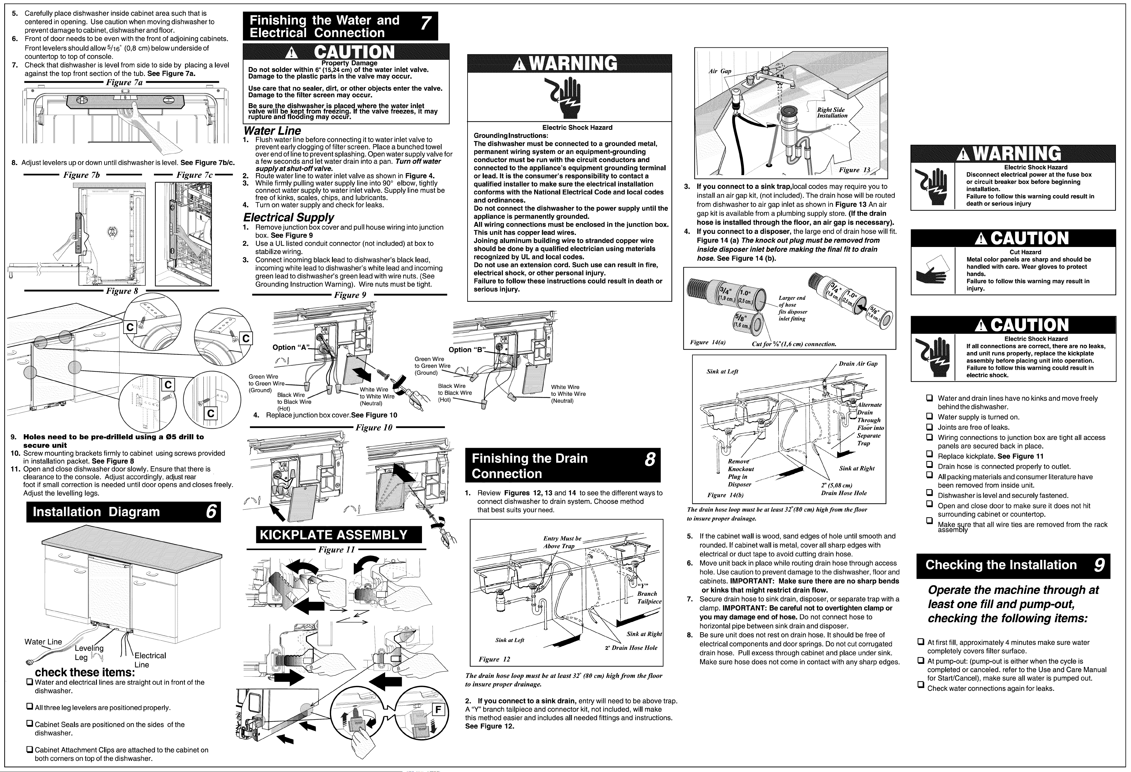
Carefully place dishwasher inside cabinet area such that is
centered in opening. Use caution when moving dishwasher to
prevent damage to cabinet, dishwasher and floor.
Front of door needs to be even with the front of adjoining cabinets.
5 "
Front levelers should allow /16 (0,8 cm) below underside of
countertop to top of console.
Check that dishwasher is level from side to side by placing a level
against the top front section of the tub. See Figure 7a.
Figure 7a
@ _ @
d
Adjust levelers up or down until dishwasher is level. See Figure 7blc.
Figure 7b I Figure 7c I
Figure 8
Property Damage
Do not solder within 6"(15,24 cm) of the water inlet valve.
Damage to the plastic parts in the valve may occur.
Use care that no sealer, dirt, or other objects enter the valve.
Damage to the filter screen may occur.
9. Holes need to be pre-drilleld using a 05 drill to
secure unit
10. Screw mounting brackets firmly to cabinet using screws provided
installation packet. See Figure 8
11. Open and close dishwasher door slowly. Ensure that there is
clearance to the console. Adjust accordingly, adjust rear
foot if small correction is needed until door opens and closes freely.
Be sure the d.ishwasheris placed where t.he water inlet
vawe will beKept.from Treezing. If the vawe freezes, it may
rupture ano nOOolng may occur.
Water Line
1. Flush water line before connecting it to water inlet valve to
prevent early clogging of filter screen. Place a bunched towel
over end of line to prevent splashing. Open water supply valve for
a few seconds and let water drain into a pan. Turn off water
supply at shut-off valve.
2. Route water line to water inlet valve as shown in Figure 4.
3. While firmly pulling water supply line into 90° elbow, tightly
connect water supply to water inlet valve. Supply line must be
free of kinks, scales, chips, and lubricants.
4. Turn on water supply and check for leaks.
Electrical Supply
1. Remove junction box cover and pull house wiring into junction
box. See Figure 9
2. Use a UL listed conduit connector (not included) at box to
stabilize wiring.
3. Connect incoming black lead to dishwasher's black lead,
incoming white lead to dishwasher's white lead and incoming
green lead to dishwasher's green lead with wire nuts. (See
Grounding Instruction Warning). Wire nuts must be tight.
Figure 9
F
Electric Shock Hazard
Grounding Instructions:
The dishwasher must be connected to a grounded metal,
permanent wiring system or an equipment-grounding
conductor must be run with the circuit conductors and
connected to the appliance's equipment grounding terminal
or lead. It is the consumer's responsibility to contact a
qualified installer to make sure the electrical installation
conforms with the National Electrical Code and local codes
and ordinances.
Do not connect the dishwasher to the power supply until the
appliance is permanently grounded.
All wiring connections must be enclosed in the junction box.
This unit has copper lead wires.
Joining aluminum building wire to stranded copper wire
should be done by a qualified electrician using materials
recognized by UL and local codes.
Do not use an extension cord. Such use can result in fire,
electrical shock, or other personal injury.
Failure to follow these instructions could result in death or
serious injury.
Option
Green Wire [/_
to Green Wire //_
Green Wire (Ground)
to Green tire_ Black Wire / /X\ f White Wire
White Wire t0 Bla?k Wire IJ _ to White Wire
, (Ground) Black Wire to White Wire
to Black Wire (Neutral) (Hot) _ _ _ (Neutral)
- -:-_':: 4 (Hot)
: .._; . Replace junction boxcover.See Figure 10
_'_,i Figure l O
in
1.
Adjust the levelling legs. Review Figures 12, 13 and 14 to see the different ways to
connect dishwasher to drain system. Choose method
that best suits your need.
Gap
i
i ii
3. If you connect to a sink trap,local codes may require you to
install an air gap kit, (not included). The drain hose will be routed
from dishwasher to air gap inlet as shown in Figure 13 An air
gap kit is available from a plumbing supply store. (If the drain
hose is installed through the floor, an air gap is necessary).
4. If you connect to a disposer, the large end of drain hose will fit.
Figure 14 (a) The knock out plug must be removed from
inside disposer inlet before making the final fit to drain
hose. See Figure 14 (b).
Larger end
"hose
fits disposer
inlet fitting
Figure 14(a) Cut %"(1, 6 cm) connection.
/ Drain Air Gap
Sink_ []
ti <-c_:_Alternate
__ I/ _ _ I I_'- _I _'--_ _l)rain
_",__ '1 li l[ _ Floor into []
.. _ J Separate
[]
"_R em ov_____ -_ _'_k_ Trap\ [][]
Knockout _ _ \ Sink at Right
Plug in _ []
Disposer 2 (5,08 cm)
Figure 14(b) Drain Hose Hole []
[]
Water Line
check these items:
Electrical
Line
[] Water and electrical lines are straight out in front of the
dishwasher.
[] All three leg levelers are positioned properly.
[] Cabinet Seals are positioned on the sides of the
dishwasher.
[] Cabinet Attachment Clips are attached to the cabinet on
both corners on top of the dishwasher.
Figure 11
The drain hose loop must be at least 32"(80 cm) high from the floor
to insure proper drainage.
[]
Entry Must be
Above Trap
##y,,
Branch
Tailpiece
Sink at Left
Figure 12
Sink at Right
2"Drain Hose Hole
The drain hose loop must be at least 32" (80 cm) high from the floor
to insure proper drainage.
5. If the cabinet wall is wood, sand edges of hole until smooth and
rounded. If cabinet wall is metal, cover all sharp edges with
electrical or duct tape to avoid cutting drain hose.
6. Move unit back in place while routing drain hose through access
hole. Use caution to prevent damage to the dishwasher, floor and
cabinets. IMPORTANT: Make sure there are no sharp bends
or kinks that might restrict drain flow.
7. Secure drain hose to sink drain, disposer, or separate trap with a
clamp. IMPORTANT: Be careful not to overtighten clamp or
you may damage end of hose. Do not connect hose to
horizontal pipe between sink drain and disposer.
8. Be sure unit does not rest on drain hose. It should be free of
electrical components and door springs. Do not cut corrugated
drain hose. Pull excess through cabinet and place under sink.
Make sure hose does not come in contact with any sharp edges.
2. If you connect to a sink drain, entry will need to be above trap.
A "Y" branch tailpiece and connector kit, not included, will make
this method easier and includes all needed fittings and instructions.
See Figure 12.
Electric Shock Hazard
Disconnect electrical power at the fuse box
or circuit breaker box before beginning
installation.
Failure to follow this warning could result in
death or serious injury
Cut Hazard
Metal color panels are sharp and should be
handled with care. Wear gloves to protect
hands.
Failure to follow this warning may result in
injury.
Electric Shock Hazard
If all connections are correct, there are no leaks,
and unit runs properly, replace the kickplate
assembly before placing unit into operation.
Failure to follow this warning could result in
electric shock.
Water and drain lines have no kinks and move freely
behind the dishwasher.
Water supply is turned on.
Joints are free of leaks.
Wiring connections to junction box are tight all access
panels are secured back in place.
Replace kickplate. See Figure 11
Drain hose is connected properly to outlet.
All packing materials and consumer literature have
been removed from inside unit.
Dishwasher is level and securely fastened.
Open and close door to make sure it does not hit
surrounding cabinet or countertop.
Make _qre that all wire ties are removed from the rack
assembly
Operate the machine through at
least one fill and pump-out,
checking the following items:
[] At first fill, approximately 4 minutes make sure water
completely covers filter surface.
[] At pump-out: (pump-out is either when the cycle is
completed or canceled, refer to the Use and Care Manual
for Start/Cancel), make sure all water is pumped out.
[] Check water connections again for leaks.